
Overview
The DIO-430-R1 is a configurable smart digital I/O module designed for digital input monitoring and relay-based output control in building automation, lighting, HVAC, alarms, and general control systems. It offers 4 opto-isolated digital inputs, 3 high-current SPDT relays, 3 user buttons, and 3 configurable user LEDs. All I/O channels are individually configurable, allowing flexible logic such as toggle, pulse, manual override, and alarm indication.
It connects via RS-485 (Modbus RTU) to a MicroPLC, MiniPLC, or any compatible controller, and can also integrate with Home Assistant (ESPHome) or SCADA/PLC systems. Configuration and diagnostics are performed through a driverless Web Serial interface via USB-C, using the browser-based WebConfig Tool. The module supports both master-controlled and standalone local logic modes.
Getting Started
Quick Setup Process
Mount & Wire – Install on 35mm DIN rail, connect 24V DC power, sensors, and relay loads.
Configure – Plug in USB-C, open the WebConfig tool in Chrome/Edge, set Modbus address and I/O mapping.
Integrate – Connect to your controller via RS-485 and start automation.
What You Need
DIO-430-R1 module
24V DC SELV power supply
RS-485 cable (twisted pair)
USB-C cable for configuration
Chromium-based browser (Chrome/Edge)
Web Configuration Steps
Connect USB-C to module and PC
Click "Connect" and select serial port
Set Modbus address (default: 3) and baud rate (default: 19200 8N1)
Configure input actions, relay mapping, LED modes, and button functions
Settings save automatically to flash
Tech Specs
| Technical Specifications | Details |
|---|---|
| Microcontroller | RP2350, Dual-core ARM Cortex-M0+ |
| Operating Voltage | 3.3V, 5V (logic), 24V DC input |
| Digital Input Pins | 4 (isolated) |
| Digital Output Pins | 3 (SPDT relay drivers) |
| User Buttons | 3 (configurable) |
| User LEDs | 3 (configurable) |
| UART | 1 (RS-485) |
| Flash Memory | 16 MB |
| EEPROM | Emulated via LittleFS |
| Built-in LEDs | Power, TX/RX indicators |
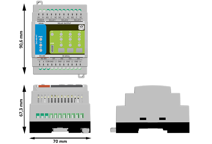
| Dimensions (W×H×D) | 70 × 90.6 × 67.3 mm |
| Weight | Approximately 120 gr. |
| Mounting | DIN-rail EN 50022 (35 mm) |
| Communication | RS-485 (Modbus RTU) |
| Configuration Interface | USB-C (Web Serial) |
| Operating Temperature | 0–40°C |
Documentation
The DIO-430-R1 is open-source hardware! You can build your own board using the following files:
Hardware Design Files
Field Board Schematic: DIO-430-R1-FieldBoard.pdf
MCU Board Schematic: DIO-430-R1-MCUBoard.pdf
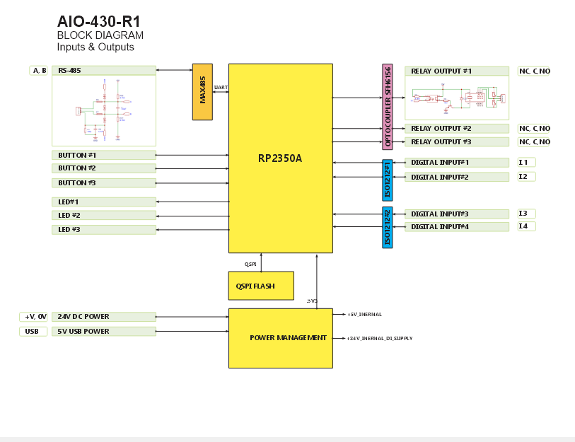
System Block Diagram: DIO_SystemBlockDiagram.png
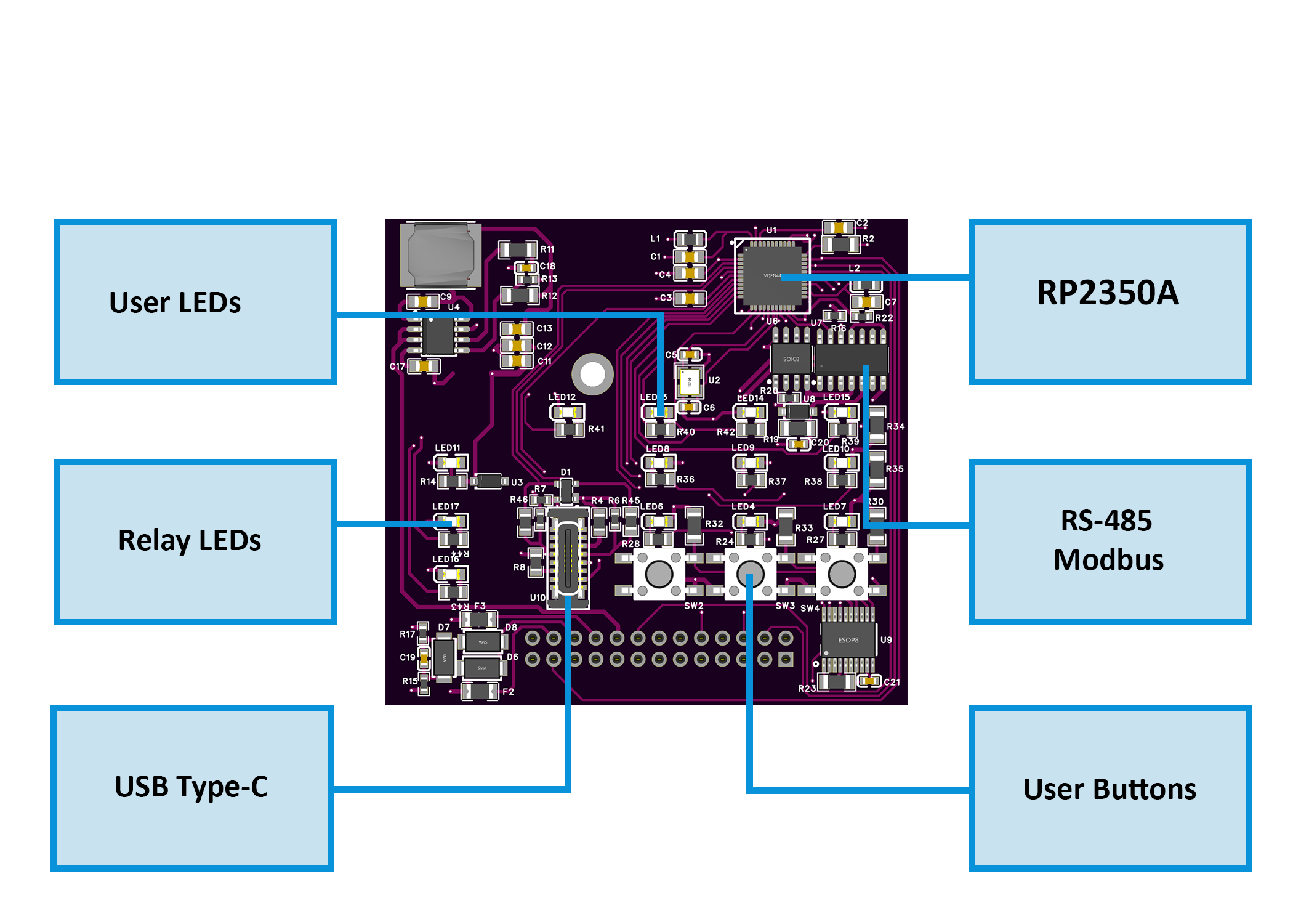
Control Board Diagram: ControlBoard_Diagram.png
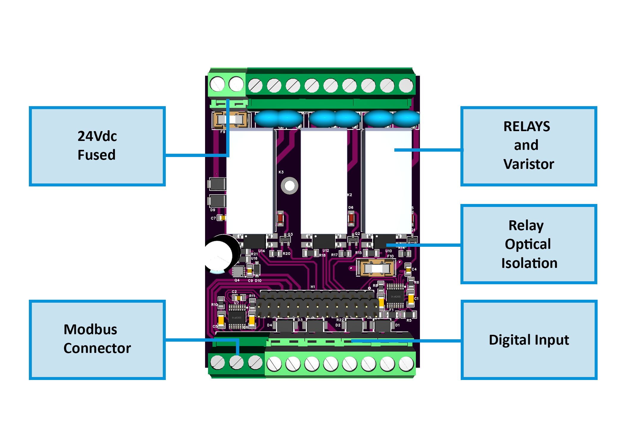
Relay Board Diagram: RelayBoard_Diagram.png
Firmware & Software
Firmware Source Code: DIO-430-R1/Firmware/
WebConfig Tool: ConfigToolPage.html
ESPHome Integration Package: default_dio_430_r1_plc.yaml
Mechanical Files
Dimensional Drawing: DIODimensions.png
All design files and documentation are available in the HomeMaster GitHub repository.
Input and Output
Digital Inputs (4 channels)
Isolated inputs compatible with dry contacts 24V signals
Individual enable/invert settings per channel
Configurable actions: None, Toggle, or Pulse
Target mapping to individual relays or all relays
PTC + TVS protection on each channel
Relay Outputs (3 channels)
SPDT contacts (NO/NC/COM)
16A @ 250V AC rating
Individual enable/invert settings
Controlled via Modbus coils or local input mapping
RC/MOV snubbers recommended for inductive loads
User Interface
3 Buttons: Configurable for relay override (toggle function)
3 LEDs: Configurable steady or blink modes, linked to relay status
Status LEDs: PWR (power), TX/RX (Modbus activity)
Communication Interfaces
Protocol: Modbus RTU
Role: Slave device
Default Settings: Address 3, 19200 baud, 8 data bits, No parity, 1 stop bit
Supported Functions: Read Coils (0x01), Read Discrete Inputs (0x02), Read Holding Registers (0x03), Read Input Registers (0x04), Write Single Coil (0x05), Write Single Register (0x06)
Modbus Address Map
Coils (Read/Write) - Function Codes 0x01, 0x05
| Address | Name | Type | Description | Access |
|---|---|---|---|---|
| 00000 | R1_CMD | Coil | Relay 1 command (1=ON, 0=OFF) | R/W |
| 00001 | R2_CMD | Coil | Relay 2 command (1=ON, 0=OFF) | R/W |
| 00002 | R3_CMD | Coil | Relay 3 command (1=ON, 0=OFF) | R/W |
| 00010 | SAVE_CFG | Coil | Write 1 to save configuration to flash | Write Only |
| 00011 | RESET | Coil | Write 1 to perform soft reset | Write Only |
| 00200 | CMD_RLY1_ON | Coil | Pulse Relay 1 ON (write 1) | Write Only |
| 00201 | CMD_RLY2_ON | Coil | Pulse Relay 2 ON (write 1) | Write Only |
| 00202 | CMD_RLY3_ON | Coil | Pulse Relay 3 ON (write 1) | Write Only |
| 00210 | CMD_RLY1_OFF | Coil | Pulse Relay 1 OFF (write 1) | Write Only |
| 00211 | CMD_RLY2_OFF | Coil | Pulse Relay 2 OFF (write 1) | Write Only |
| 00212 | CMD_RLY3_OFF | Coil | Pulse Relay 3 OFF (write 1) | Write Only |
Discrete Inputs (Read Only) - Function Code 0x02
| Address | Name | Type | Description |
|---|---|---|---|
| 10000 | DI1_STATE | Discrete Input | Digital Input 1 state (post-invert) |
| 10001 | DI2_STATE | Discrete Input | Digital Input 2 state (post-invert) |
| 10002 | DI3_STATE | Discrete Input | Digital Input 3 state (post-invert) |
| 10003 | DI4_STATE | Discrete Input | Digital Input 4 state (post-invert) |
| 10060 | R1_STATE | Discrete Input | Relay 1 actual state |
| 10061 | R2_STATE | Discrete Input | Relay 2 actual state |
| 10062 | R3_STATE | Discrete Input | Relay 3 actual state |
| 10090 | LED1_STATE | Discrete Input | LED 1 state |
| 10091 | LED2_STATE | Discrete Input | LED 2 state |
| 10092 | LED3_STATE | Discrete Input | LED 3 state |
Holding Registers (Read/Write) - Function Codes 0x03, 0x06
| Address | Name | Type | Description | Range/Values |
|---|---|---|---|---|
| 40000 | MODEL_ID | Register | Module model identifier (0x0430) | Read Only |
| 40001 | FW_VERSION | Register | Firmware build YYYYMM | Read Only |
| 40002 | MB_ADDR | Register | Modbus address (1-255) | R/W (1-255) |
| 40003 | MB_BAUD | Register | Baud rate setting | 0=9600, 1=19200, 2=38400, 3=57600, 4=115200 |
| 40004 | MB_PARITY | Register | Parity setting | 0=None, 1=Even, 2=Odd |
| 40010 | DI_EN_MASK | Register | Digital Input enable mask (bits 0-3) | Bitmask |
| 40011 | DI_INV_MASK | Register | Digital Input invert mask (bits 0-3) | Bitmask |
| 40012 | DI1_ACTION | Register | DI1 action mode | 0=None, 1=Toggle, 2=Pulse |
| 40013 | DI2_ACTION | Register | DI2 action mode | 0=None, 1=Toggle, 2=Pulse |
| 40014 | DI3_ACTION | Register | DI3 action mode | 0=None, 1=Toggle, 2=Pulse |
| 40015 | DI4_ACTION | Register | DI4 action mode | 0=None, 1=Toggle, 2=Pulse |
| 40016 | DI1_TARGET | Register | DI1 target relay | 4=None, 0=All, 1=R1, 2=R2, 3=R3 |
| 40017 | DI2_TARGET | Register | DI2 target relay | 4=None, 0=All, 1=R1, 2=R2, 3=R3 |
| 40018 | DI3_TARGET | Register | DI3 target relay | 4=None, 0=All, 1=R1, 2=R2, 3=R3 |
| 40019 | DI4_TARGET | Register | DI4 target relay | 4=None, 0=All, 1=R1, 2=R2, 3=R3 |
| 40020 | RLY_EN_MASK | Register | Relay enable mask (bits 0-2) | Bitmask |
| 40021 | RLY_INV_MASK | Register | Relay invert mask (bits 0-2) | Bitmask |
| 40022 | BTN1_ACTION | Register | Button 1 action | 0=None, 5=R1 toggle, 6=R2 toggle, 7=R3 toggle |
| 40023 | BTN2_ACTION | Register | Button 2 action | 0=None, 5=R1 toggle, 6=R2 toggle, 7=R3 toggle |
| 40024 | BTN3_ACTION | Register | Button 3 action | 0=None, 5=R1 toggle, 6=R2 toggle, 7=R3 toggle |
| 40025 | LED_MODE | Register | LED mode configuration | Bits 0-1: LED1, Bits 2-3: LED2, Bits 4-5: LED3 (0=Steady, 1=Blink) |
| 40030 | UPTIME_LO | Register | Uptime seconds (lower 16 bits) | Read Only |
| 40031 | UPTIME_HI | Register | Uptime seconds (upper 16 bits) | Read Only |
| 40032 | ERROR_CODE | Register | Last error code | Read Only |
| 40033 | STATUS_FLAGS | Register | Status flags | Read Only |
Input Registers (Read Only) - Function Code 0x04
| Address | Name | Type | Description |
|---|---|---|---|
| 30000 | DI_STATE_MASK | Register | Digital Input state mask (bits 0-3) |
| 30001 | RLY_STATE_MASK | Register | Relay state mask (bits 0-2) |
| 30002 | BTN_STATE_MASK | Register | Button state mask (bits 0-2) |
| 30003 | LED_STATE_MASK | Register | LED state mask (bits 0-2) |
Home Assistant & ESPHome Integration Guide
Overview
The DIO-430-R1 integrates seamlessly with Home Assistant via ESPHome using the Modbus RTU protocol. This guide covers both quick integration using our pre-built package and manual configuration for advanced users.
Prerequisites
Before starting, ensure you have:
ESPHome device (HomeMaster MiniPLC/MicroPLC or any ESP32/ESP8266 with RS-485)
RS-485 connection between ESP device and DIO-430-R1
24V power to DIO-430-R1 module
Home Assistant with ESPHome add-on installed
Configure Your ESPHome Device
Add this to your ESPHome YAML configuration:
# RS-485 Configuration
uart:
  id: uart_modbus
  tx_pin: GPIO17
  rx_pin: GPIO16
  baud_rate: 19200
  parity: NONE
  stop_bits: 1

modbus:
  id: modbus_bus
  uart_id: uart_modbus

# Import DIO-430-R1 Package
packages:
  dio_430_r1:
    url: https://github.com/isystemsautomation/HOMEMASTER
    ref: main
    files:
      - path: DIO-430-R1/Firmware/default_dio_430_r1_plc/default_dio_430_r1_plc.yaml
        vars:
          dio_prefix: "Staircase"  # Custom name for your entities
          dio_id: staircase_module  # Unique internal ID
          dio_address: 3  # Must match WebConfig Modbus address
    refresh: 1d
Customize Variables
dio_prefix: Appears in entity names (e.g., "Staircase Relay 1")
dio_id: Must be unique if adding multiple DIO modules
dio_address: Set to match your DIO-430-R1 Modbus address (default: 3)
Multiple DIO Modules
For additional modules, duplicate the package block with unique IDs:
packages:
  dio_lights:
    url: https://github.com/isystemsautomation/HOMEMASTER
    ref: main
    files:
      - path: DIO-430-R1/Firmware/default_dio_430_r1_plc/default_dio_430_r1_plc.yaml
        vars:
          dio_prefix: "Kitchen"
          dio_id: kitchen_module
          dio_address: 4
    refresh: 1d

  dio_hvac:
    url: https://github.com/isystemsautomation/HOMEMASTER
    ref: main
    files:
      - path: DIO-430-R1/Firmware/default_dio_430_r1_plc/default_dio_430_r1_plc.yaml
        vars:
          dio_prefix: "HVAC"
          dio_id: hvac_module
          dio_address: 5
    refresh: 1d
Programming
Supported Development Environments
Arduino IDE with RP2350 support
PlatformIO with RP2350 toolchain
MicroPython (community builds available)
Firmware Flashing
Connect USB-C to PC
Hold Buttons 2 + 3 to enter BOOT mode
Upload via:
UF2 drag-and-drop to mounted drive, OR
PlatformIO/Arduino IDE upload
Press Buttons 1 + 3 for hardware reset if needed
Pin Mapping (Default Firmware)
Pin Name | GPIO | Function |
|---|---|---|
IN1 | GPIO6 | Digital Input 1 |
IN2 | GPIO11 | Digital Input 2 |
IN3 | GPIO12 | Digital Input 3 |
IN4 | GPIO7 | Digital Input 4 |
RLY1 | GPIO10 | Relay 1 Driver |
RLY2 | GPIO9 | Relay 2 Driver |
RLY3 | GPIO8 | Relay 3 Driver |
BTN1 | GPIO1 | Button 1 |
BTN2 | GPIO2 | Button 2 |
BTN3 | GPIO3 | Button 3 |
LED1 | GPIO13 | User LED 1 |
LED2 | GPIO14 | User LED 2 |
LED3 | GPIO15 | User LED 3 |
RS485_TX | GPIO4 | RS-485 Transmit |
RS485_RX | GPIO5 | RS-485 Receive |
Related products
These other products might interest you