
HomeMaster ALM-173-R1
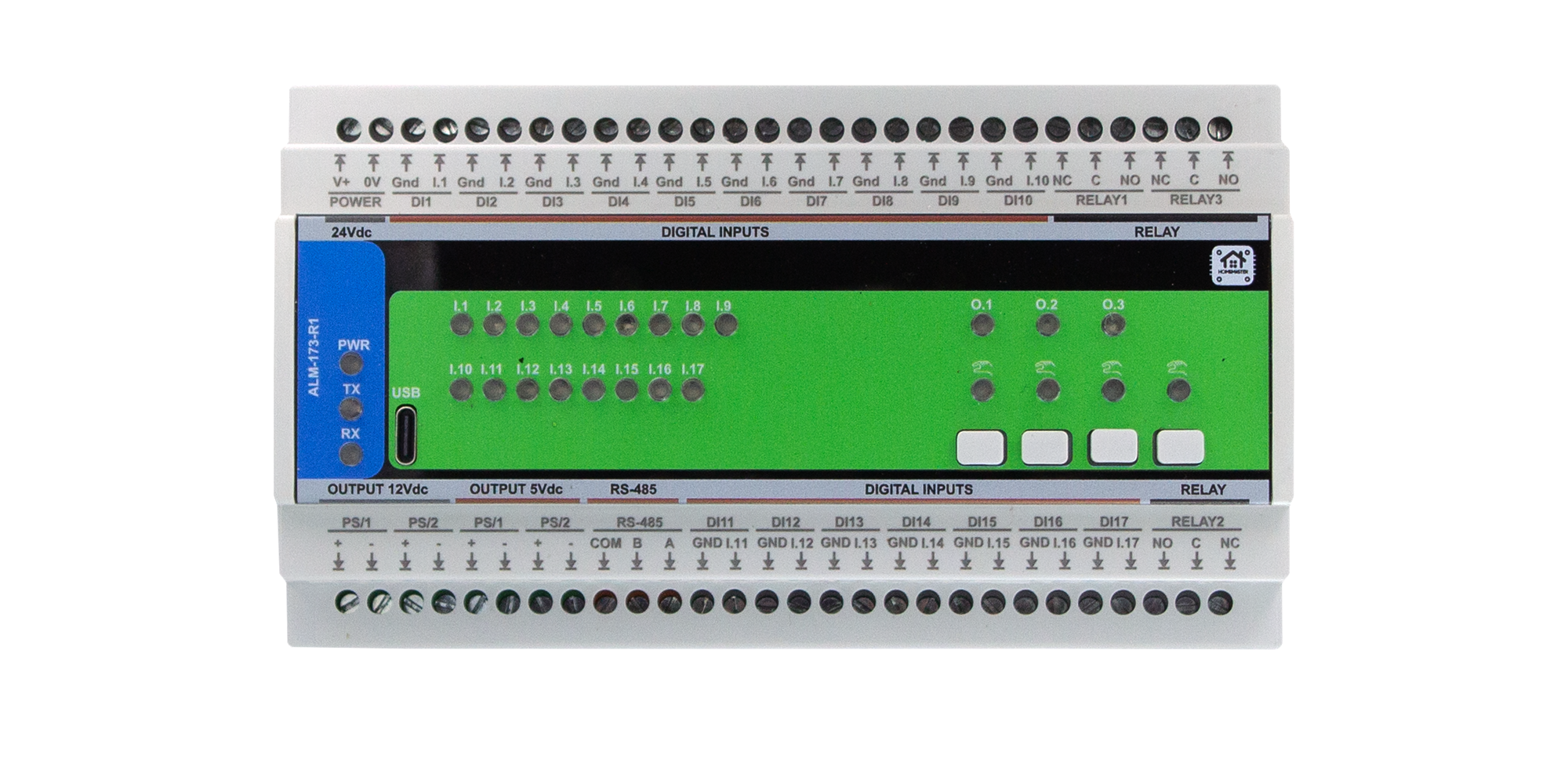
The HomeMaster ALM-173-R1 is a configurable alarm and annunciator I/O module for intrusion detection, fault signalling and supervision. It combines 17 opto-isolated digital inputs, 3 SPDT relay outputs, and a small front-panel HMI with 4 buttons and 4 LEDs to build flexible alarm panels and summary annunciators in building and light industrial automation.
The module connects to a MicroPLC/MiniPLC or any Modbus RTU master over RS‑485 and is configured via a browser-based WebConfig UI over USB‑C (Web Serial). Local firmware runs alarm groups, latching and acknowledgements; Modbus exposes all inputs, alarm bits, relay states and overrides to PLC/SCADA and Home Assistant.
Quick Overview
- Alarm and annunciator I/O expansion module for Modbus automation systems
- DIN-rail form factor with 24 V DC SELV supply
- 17 opto-isolated digital inputs with per-input enable, invert and group
- 3 SPDT relays driven by alarm groups, master or manual override
- Front panel with 4 buttons (ack/override) and 4 LEDs (status/alert)
- RS-485 Modbus RTU communication (address 1–255, 9600–115200 baud)
- Local configuration via USB‑C WebConfig interface
- Persistent configuration stored in external QSPI flash
Typical Applications
- Intrusion and zone alarm panels
- Equipment room and plant fault annunciators
- Summary alarm modules for BMS and SCADA
- Door and access control supervision
- Process and utility alarm aggregation (Any / Group 1–3)
- Alarm expansion for Home Assistant via ESPHome
- Retrofitting alarm panels to Modbus RTU
Tech Specs
| Specification | Details |
|---|---|
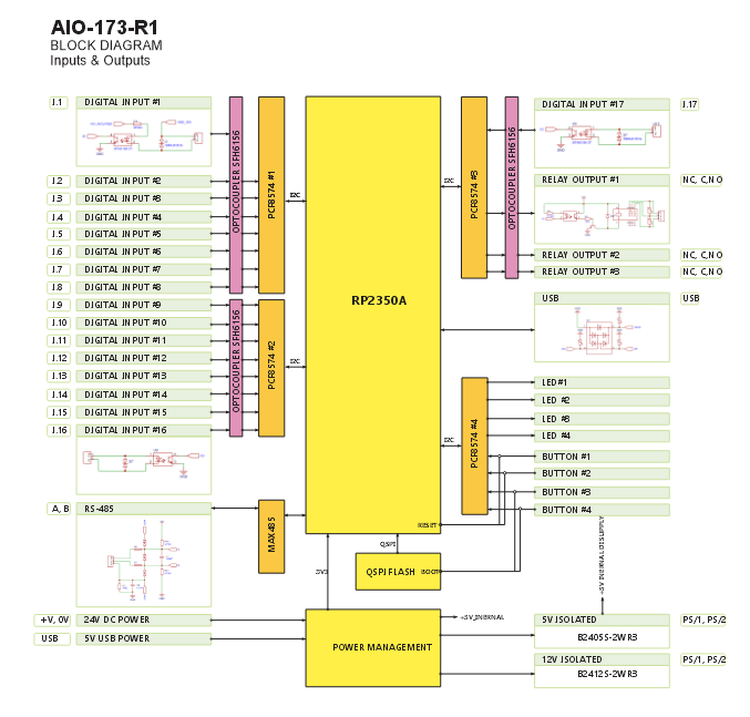
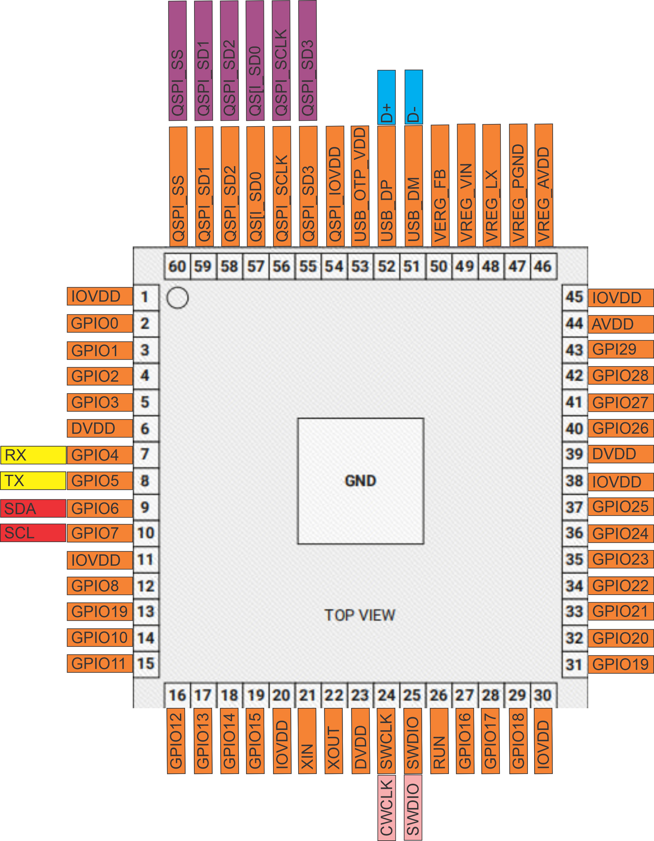
| Microcontroller | RP2350A dual-core microcontroller |
| Flash Memory | External QSPI Flash (W25Q32) |
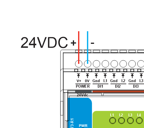
| Power Input | 24 V DC SELV nominal (V+ / 0V), protected input |
| Digital Inputs | 17 × opto-isolated digital inputs (IN1…IN17, each with own GND_ISO return); dry contact / isolated low-voltage; per-input Enable / Invert / Group (None, G1, G2, G3) |
| Relay Outputs | 3 × SPDT relays (RLY1…RLY3), dry contacts COM/NO/NC; system rating limited by PCB and terminal paths (see datasheet; use external contactors for high or inductive loads) |
| User Interface | 4 configurable buttons (ack/override) and 4 user LEDs (steady or blink) plus PWR/TX/RX status LEDs |
| Communication | RS‑485 Modbus RTU (A/B/COM), half‑duplex, TVS and PTC protection, fail-safe biasing |
| USB | USB‑C (ESD/EMI protected), Web Serial configuration and firmware upload |
| Sensor Rails | Isolated +12 V ISO (PS/1) and +5 V ISO (PS/2) rails for low‑power sensors only (PTC/fuse protected) |
| Modbus Address Range | 1–255 (default: 3) |
| Modbus Baud Rate | 9600–115200 (default: 19200, 8N1) |
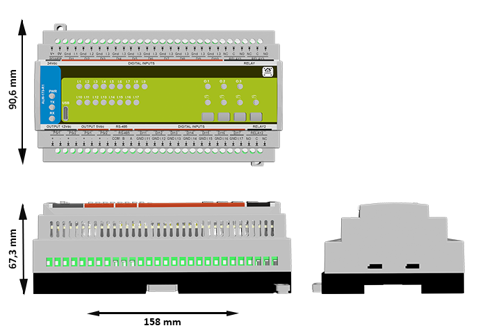
| Mechanical Size | Approx. 157.4 × 91 × 58.4 mm (L × W × H); DIN‑rail enclosure |
Installation, Environmental & Mechanical
| Category | Specification | Details |
|---|---|---|
| Terminal Specifications | Terminal type | Pluggable screw terminal blocks, 5.08 mm pitch |
| Terminal pitch | 5.08 mm | |
| Wire cross-section | 0.2–2.5 mm² (AWG 24–12) | |
| Conductor type | Solid or stranded copper; ferrules recommended for stranded | |
| Tightening torque | 0.4 Nm (max) | |
| Terminal access | Front wiring in control cabinet | |
| Environmental Ratings | Operating temperature | 0 °C to +40 °C |
| Storage temperature | −10 °C to +55 °C | |
| Relative humidity | 0–95 % RH, non-condensing | |
| Ingress protection | IP20 (indoor cabinet) | |
| Installation | Indoor control cabinet only; not for outdoor or exposed installation | |
| Altitude | Up to 2000 m above sea level (per datasheet) | |
| Mechanical & Packaging | Product dimensions | 157.4 × 91 × 58.4 mm (L × W × H) |
| Mounting | 35 mm DIN rail (EN 50022) | |
| Enclosure | PC/ABS V‑0 industrial enclosure | |
| Protection class | SELV, pollution degree 2 | |
| Net/gross weight | See datasheet for latest values | |
| Notes | All dimensions and masses as per latest official datasheet |
Install only inside a dry, ventilated control cabinet with a protective front plate covering all wiring terminals and a closing door.
All wiring terminals must be protected against accidental contact by an insulating front plate, wiring duct or terminal cover.
Home Assistant / Modbus / Web Config Integration
The ALM-173-R1 is designed as a Modbus RTU alarm endpoint that can be used with:
- HomeMaster MicroPLC and MiniPLC controllers (ESPHome based)
- Third‑party PLC and SCADA systems via Modbus RTU
- Home Assistant using an ESPHome‑based controller or Modbus integration
- Direct USB‑C configuration using a Chromium browser WebConfig tool
Internal firmware implements alarm groups (G1–G3 + Any), latching vs active‑while modes, relay follow/master/override logic and LED/button behavior. Configuration is stored in flash and automatically restored at power‑up.
Quick Setup Process (USB‑C WebConfig)
- Mount & Power – Mount the module on a DIN rail, wire 24 V DC and RS‑485.
- Connect USB‑C – Connect the module to a PC using a USB‑C cable.
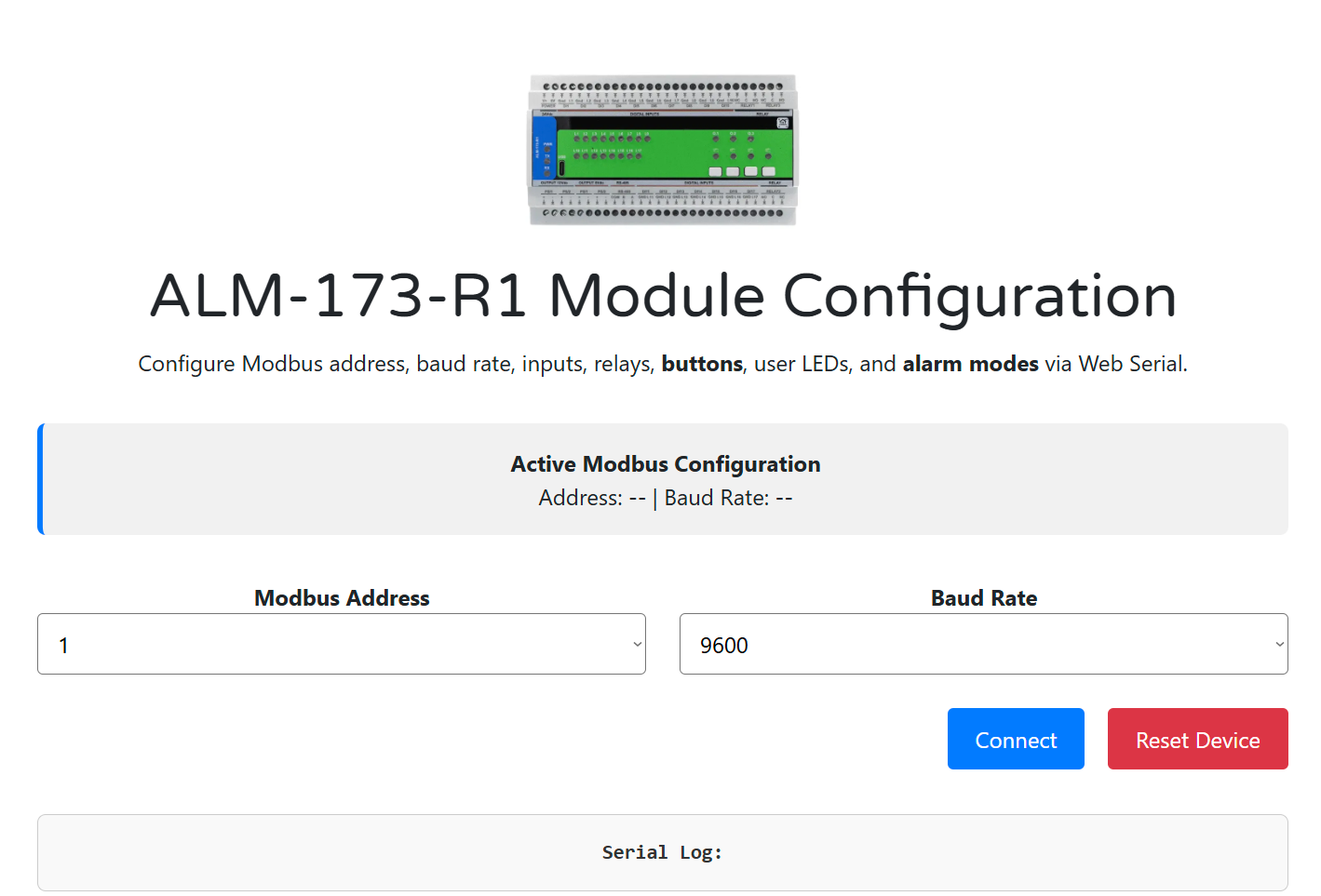
- Open WebConfig – Open configtool-alm-173-r1 in Chrome or Edge.
- Connect Device – Click Connect, select the serial device and wait for Active Modbus Configuration to appear.
- Configure – Set Modbus address and baud, choose alarm modes for G1–G3.
- Map I/O – Assign inputs to groups, configure relays, LEDs and buttons.
- Save & Disconnect – Settings are stored in flash; disconnect USB‑C and hand over control to the Modbus master.
What WebConfig is and how it works: WebConfig is a browser-based configuration UI that runs entirely in a Chromium browser using the Web Serial API. It shows live Modbus address/baud in the header, streams a serial log, and lets you edit alarm modes, input groups, relay behavior, button actions and LED mapping. Changes apply immediately and are written to flash shortly after the last update so that configuration survives power cycles.
WebConfig Configuration Options
- Modbus address (1–255) and baud rate (9600–115200)
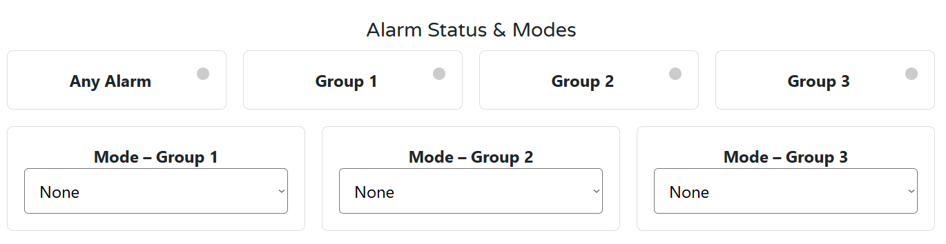
- Alarm modes per group: None / Active‑while / Latched‑until‑ack
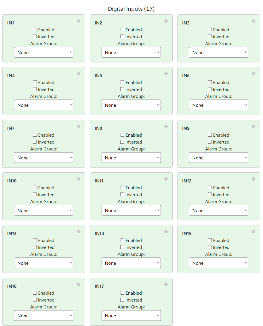
- Digital inputs: Enable / Invert / Alarm Group (None/1/2/3)
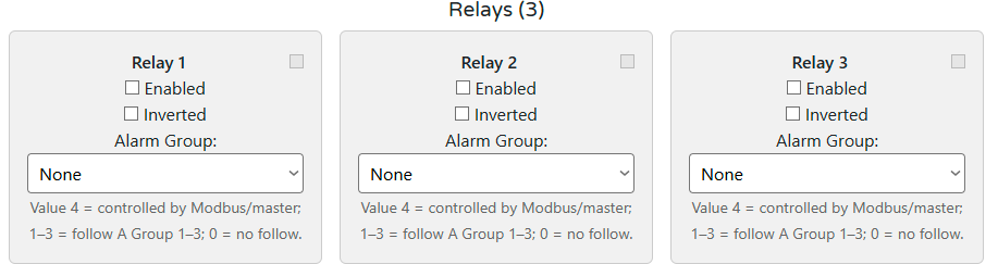
- Relays: Enable / Invert / Source (Group 1–3, Master, or None)
- Buttons: Ack All, Ack G1–G3, or Relay 1–3 override
- LEDs: Steady/Blink, source Any, G1–G3, or relay override
Minimal ESPHome YAML (Controller side)
Example controller configuration to enable Modbus and import the ALM package:
uart:
  id: uart_modbus
  tx_pin: 17
  rx_pin: 16
  baud_rate: 19200
  parity: NONE
  stop_bits: 1

modbus:
  id: modbus_bus
  uart_id: uart_modbus

packages:
  alm1:
    url: https://github.com/isystemsautomation/HOMEMASTER
    ref: main
    files:
      - path: ALM-173-R1/Firmware/default_alm_173_r1_plc/default_alm_173_r1_plc.yaml
        vars:
          alm_prefix: "ALM#1"   # shown in Home Assistant
          alm_id: alm_1         # unique internal ID
          alm_address: 5        # Modbus address set in WebConfig
    refresh: 1d
alm_address must match the Modbus address configured in WebConfig.
Documentation
The ALM-173-R1 is open-source hardware. Hardware, firmware and integration documentation are available in the repository.
Hardware Design Files
| File | Description | Link |
|---|---|---|
| Field Board Schematic | Digital inputs, relays and isolated sensor rails | ALM-173-R1-FieldBoard.pdf |
| MCU Board Schematic | Controller, RS‑485, USB‑C, logic supply and expanders | ALM-173-R1-MCUBoard.pdf |
Firmware & Software
| Resource | Description | Link |
|---|---|---|
| Firmware Source Code | Alarm engine, Modbus RTU firmware and Web Serial configuration page | GitHub Firmware folder |
| Integration Guide | Detailed Modbus map, wiring, WebConfig and ESPHome integration | README.md |
| WebConfig Tool | Browser-based configuration interface over USB‑C Web Serial | ConfigToolPage.html |
Cabling and wirings
24 V DC Power Supply
Digital Inputs (IN1…IN17)
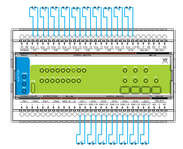
- 17 opto-isolated digital inputs (IN1…IN17) referenced to isolated GND_ISO returns.
- Intended for dry contacts / isolated low-voltage signals; do not connect mains or non-SELV circuits.
- Per-input configuration in WebConfig: Enable, Invert (for NC sensors) and Alarm Group (None / G1 / G2 / G3).
- Inputs feed the internal alarm engine, which generates Any Alarm and per-group (G1–G3) status bits exposed via Modbus.
- Use shielded twisted pair and keep DI wiring away from high‑dv/dt or high‑current cables for best noise immunity.
Relay Outputs
The ALM-173-R1 provides 3 SPDT mechanical relays for switching external loads using dry contacts. Each relay exposes NO / NC / COM terminals and is driven via isolated control circuitry from the MCU.
Rating: the relay outputs are limited by the PCB copper and terminal system rating as specified in the official datasheet. For higher power or inductive loads, use external contactors or power relays and treat the ALM relays as control contacts only.
External protection required: Every relay output must be protected by an external fuse or circuit breaker sized according to the load and system limits. Relay output circuits are not internally fused, so external overcurrent protection is mandatory for safe operation.
Relay Specifications
| Channel | Contacts | Type | Typical Use |
|---|---|---|---|
| Relay 1 | NO / NC / COM | SPDT | Alarm or siren output (group or master controlled) |
| Relay 2 | NO / NC / COM | SPDT | Zone or summary alarm output |
| Relay 3 | NO / NC / COM | SPDT | Additional alarm, strobe or fault contact |
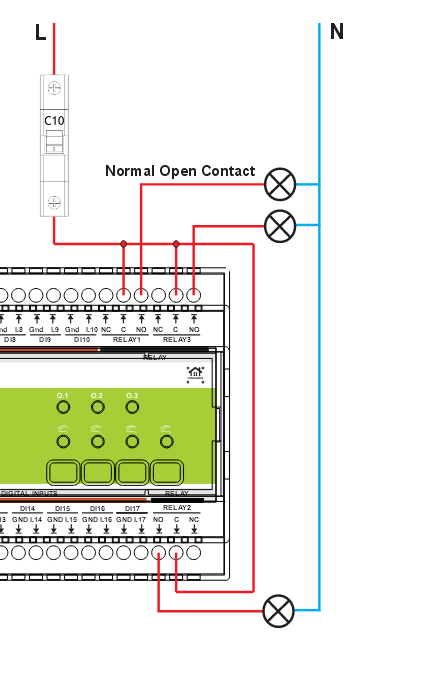
- Each relay has COM / NO / NC terminals.
- Use NO for default-OFF loads, and NC for default-ON loads.
- Loads connected to relay contacts may carry hazardous voltage depending on your external wiring.
- Supports AC and DC switching; observe derating for DC and inductive loads as per contact manufacturer data.
Common protection warning: If a single common fuse or circuit breaker is used to protect multiple relay outputs, its rating must not be chosen by summing relay currents. The protective device rating must respect the per-output system limit and applicable standards.
For inductive or DC loads (contactors, solenoids, motors), use appropriate suppression (RC snubbers, MOVs, or flyback diodes). Loads exceeding recommended PCB current limits must be switched using external contactors or wiring that bypasses PCB copper paths.
Communication & Protocols
- Modbus RTU (RS‑485) – primary field bus for controller integration
RS‑485 Communication
| Parameter | Specification |
|---|---|
| Protocol | Modbus RTU |
| Interface | RS‑485 half-duplex |
| Terminals | A / B / COM |
| Default Address | 3 (changeable 1–255 via WebConfig) |
| Default Baud Rate | 19200 (selectable 9600–115200, 8N1) |
| Data Bits | 8 |
| Parity | None |
| Stop Bits | 1 |
Uses an RS‑485 transceiver with surge and overcurrent protection; see schematics for exact component references.
RS‑485 Wiring
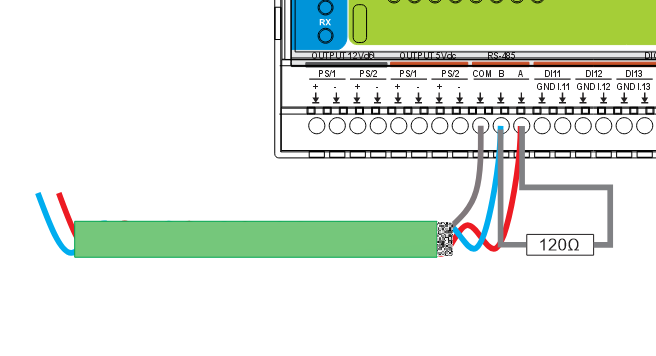
Termination & Biasing
- Terminate the RS‑485 line with approximately 120 Ω resistors at the two physical ends of the bus only.
- Do not terminate intermediate devices.
- Provide fail-safe biasing at the controller/master as recommended for Modbus RTU networks.
COM / Reference Ground
- Connect COM (reference ground) between all RS‑485 nodes when separate power supplies are used.
- This limits common‑mode voltage and helps prevent communication faults.
A common 0 V reference between controller and ALM module improves noise immunity and reduces RS‑485 communication errors.
USB‑C Interface
| Parameter | Specification |
|---|---|
| Function | Configuration and diagnostics via Web Serial (WebConfig) |
| Interface | USB‑C |
| Protocol | USB serial (CDC) presented to the browser |
| Purpose | Setting Modbus parameters, mapping inputs/relays/LEDs/buttons, and monitoring the serial log |
Cable Recommendations & Shield Grounding
General Routing Rules
- Route signal wiring (digital inputs, RS‑485, sensor rails) separately from relay load wiring and mains bundles.
- Avoid long parallel runs with contactor, motor or VFD cables; cross at 90° where needed.
- Use wiring ducts and strain relief to keep cables organised and protected.
Digital Inputs (IN1…IN17)
- Use 2‑core twisted pair per input (INx + GND I.x).
- Recommended size: 0.2–0.75 mm² (AWG 24–18).
- For long runs and noisy environments, use shielded twisted pair and route away from high‑dv/dt wiring.
- Inputs are for dry contacts / isolated low voltage only. Do not connect mains or high‑energy circuits.
RS‑485 (Modbus) Cable
- Use twisted pair for A/B; prefer shielded twisted pair.
- Implement a true daisy‑chain bus; avoid star topologies and long stubs.
- Terminate with 120 Ω at both physical ends of the trunk.
- Share COM/GND between devices to control common‑mode voltage.
Shield Grounding
- Terminate cable shields at one end only, typically at the controller or main panel earth bar.
- Bond shield to PE/EMC ground using a short, low‑impedance connection (clamp or grounding bar).
- Do not connect shields to signal terminals (A/B/COM, INx, GND I.x).
- Keep shield terminations short and separated from high‑energy conductors.
System Architecture & Pinout
Safety and Installation Notes
- Use only SELV 24 V DC power supplies. Never connect mains voltage to logic, inputs or relay terminals.
- Install inside a clean, dry, ventilated enclosure on a 35 mm DIN rail.
- Protect all wiring terminals against accidental contact using covers or ducts.
- Observe relay contact ratings; use external contactors and snubbers for inductive or high power loads.
- Separate field I/O wiring from mains and high‑energy conductors to reduce EMI and improve safety.
- Installation and servicing must be performed by qualified personnel familiar with panel building and low‑voltage safety.
Compliance & Certifications
The HomeMaster ALM-173-R1 is designed to comply with the applicable European Union directives. ISYSTEMS AUTOMATION (HomeMaster brand) maintains the technical documentation and a signed EU Declaration of Conformity (DoC).
EU Directives
EMC 2014/30/EU · LVD 2014/35/EU · RoHS 2011/65/EU
Harmonised Standards
| Area | Standards |
|---|---|
| EMC | EN 55032 (Emissions) · EN 55035 (Immunity) |
| Electrical Safety | EN 62368-1 |
| RoHS | EN IEC 63000 |
Equipment Classification
Class A Information Technology Equipment (industrial / commercial environment)
Safety Notice
24 V DC: SELV · Qualified personnel only
Related products
These other products might interest you