
Overview
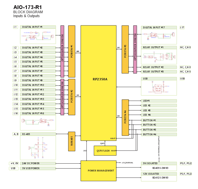
The ALM-173-R1 is a modular alarm I/O device featuring 17 opto-isolated inputs, 3 SPDT relays, and local buttons and LEDs. It connects via RS-485 (Modbus RTU) to a MicroPLC, MiniPLC, or any compatible controller, and can integrate with Home Assistant (ESPHome) or SCADA/PLC systems. Configuration is performed through a driverless Web Serial interface via USB-C, using the browser-based WebConfig Tool. The module supports both master-controlled and standalone local logic modes, with configurable alarm groups and acknowledgment logic.
Getting Started
Quick Setup Process
Mount & Wire – Install on 35mm DIN rail, connect 24V DC power, sensors, and relay loads.
Configure – Plug in USB-C, open the WebConfig tool in Chrome/Edge, set Modbus address and I/O mapping.
Integrate – Connect to your controller via RS-485 and start automation.
What You Need
ALM-173-R1 module
24 VDC SELV power supply
RS-485 cable (twisted pair)
USB-C cable for configuration
Chromium-based browser (Chrome/Edge)
Web Configuration Steps
Connect USB-C to module and PC
Click "Connect" and select serial port
Set Modbus address (default: 3) and baud rate (default: 19200 8N1)
Configure input actions, relay mapping, LED modes, and button functions
Settings save automatically to flash
Tech Specs
| Feature | Details |
|---|---|
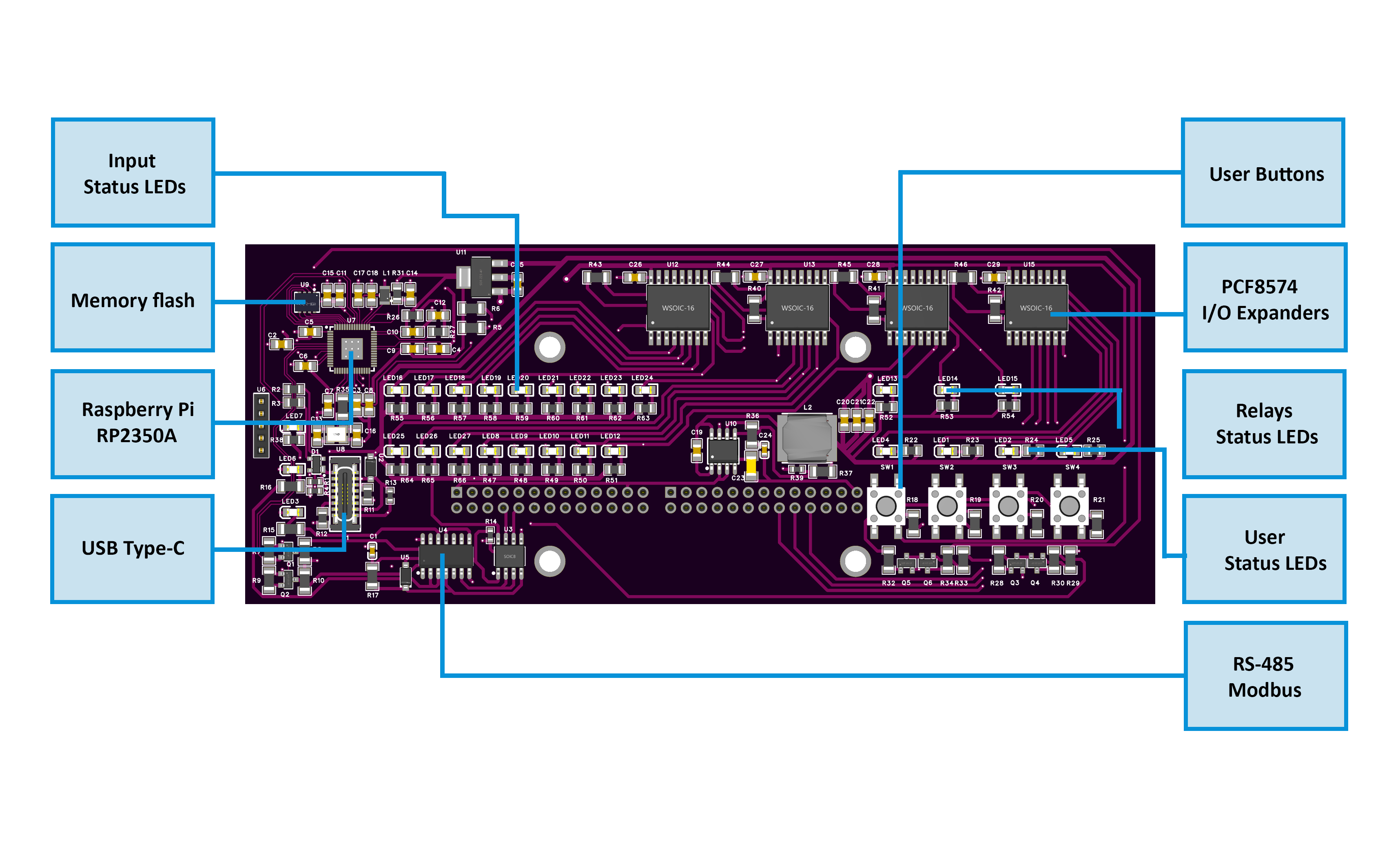
| Microcontroller | RP2350, Dual-core ARM Cortex-M0+ |
| Operating Voltage | 24 VDC input (SELV) |
| Digital Inputs | 17 (opto-isolated) |
| Relay Outputs | 3 (SPDT, 16 A @ 250 V AC) |
| User Buttons | 4 (configurable) |
| User LEDs | 4 (configurable) |
| Communication | RS-485 (Modbus RTU) |
| Configuration Interface | USB-C (Web Serial) |
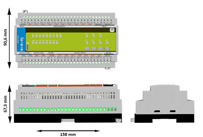
| Dimensions (W×H×D) | 157.4 × 91 × 58.4 mm |
| Operating Temperature | 0–40°C |
Documentation
The DIO-430-R1 is open-source hardware! You can build your own board using the following files:
Hardware Design Files
MCU Board Schematic: ALM-173-R1-MCUBoard.pdf
Field Board Schematic: ALM-173-R1-FieldBoard.pdf
System Block Diagram: ALM_SystemBlockDiagram.png
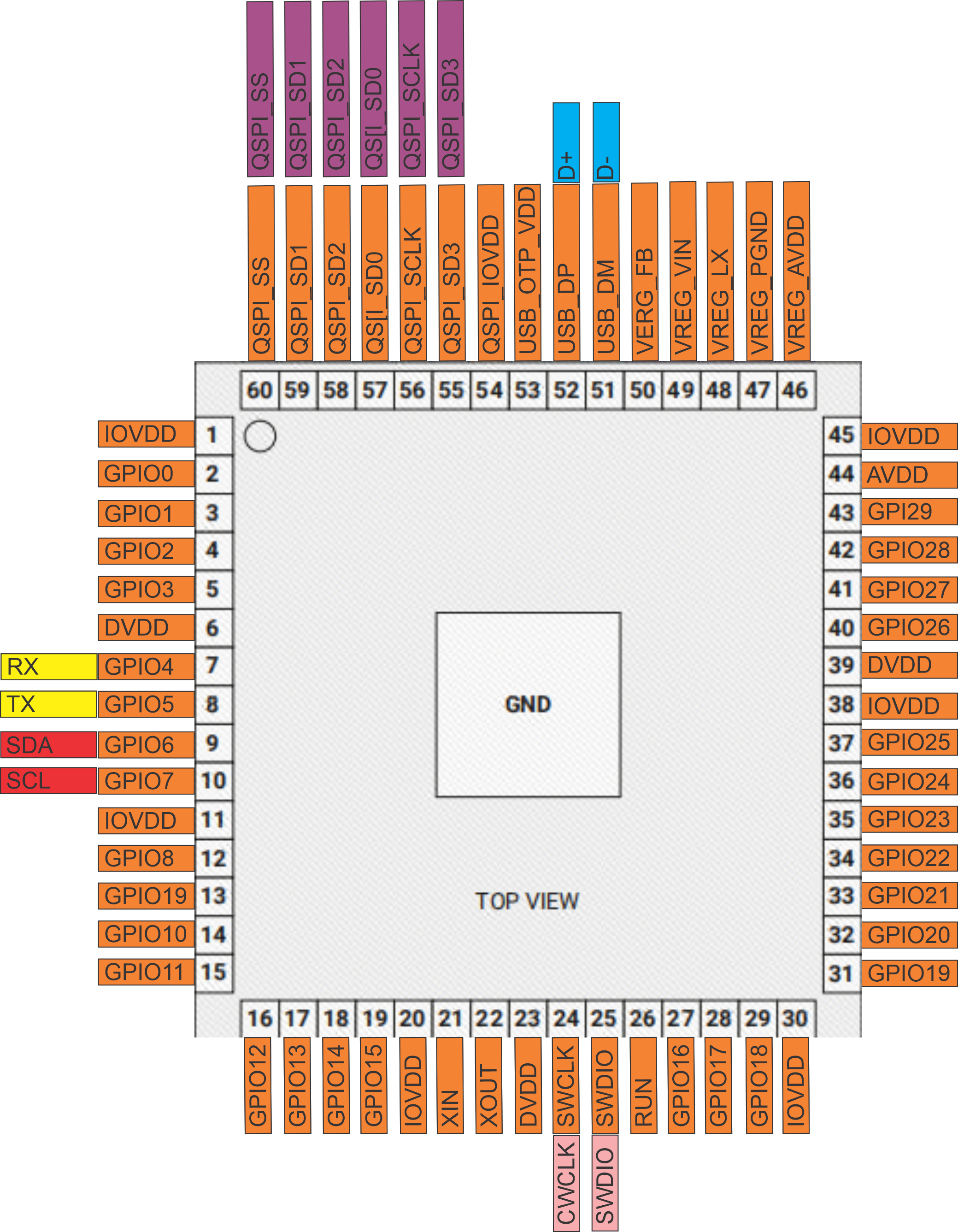
MCU Pinout Diagram: ALM_MCU_Pinouts.png
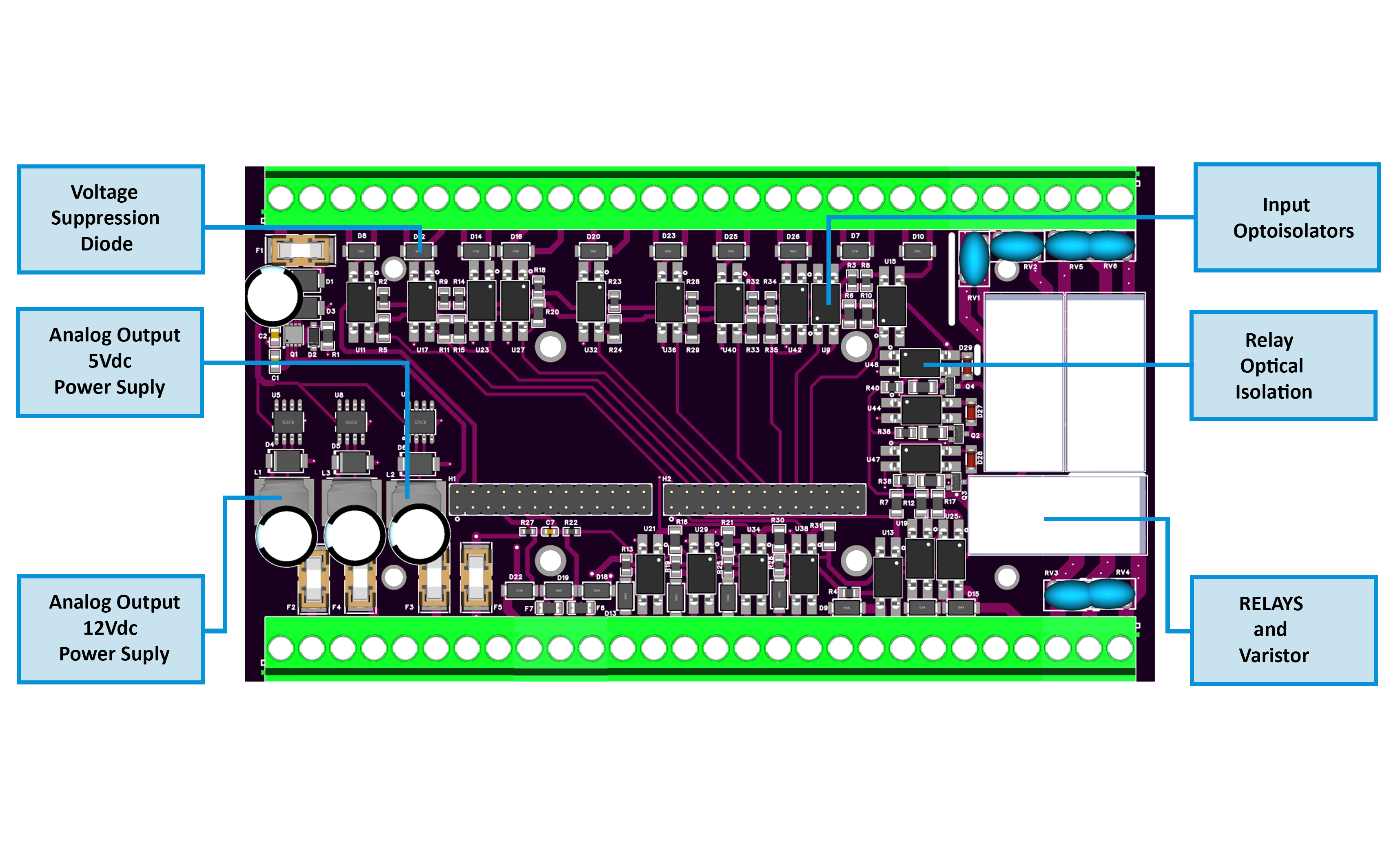
Field Board Layout: FieldBoard-Diagram.png
MCU Board Layout: MCUBoard-Diagram.png
Firmware & Software
Firmware Source Code: ALM-173-R1/Firmware/
WebConfig Tool: ConfigToolPage.html
ESPHome Integration Package: default_alm_173_r1_plc.yaml
Mechanical Files
Dimensional Drawing: ALMMDimensions.png
All design files and documentation are available in the HomeMaster GitHub repository.
Input and Output
Digital Inputs (17 channels)
Opto-isolated inputs with TVS/PTC protection
Per-channel settings: Enable, Invert, Alarm Group (1/2/3/None)
Configurable debounce and latching logic
Relay Outputs (3 channels)
SPDT contacts (NO/NC/COM)
16 A @ 250 V AC rating
Individual enable/invert settings
Can follow alarm groups, Modbus commands, or manual override
Alarm Groups
3 independent alarm groups + “Any Alarm” summary
Modes: Active-while, Latched-until-acknowledged
Local acknowledgment via buttons or Modbus
User Interface
4 Buttons: Configurable for acknowledgment or relay override
4 LEDs: Configurable steady/blink modes, linked to alarm groups or relay state
Status LEDs: PWR, TX/RX (Modbus activity)
Communication Interfaces
Protocol: Modbus RTU
Role: Slave device
Default Settings: Address 3, 19200 baud, 8 data bits, No parity, 1 stop bit
Supported Functions: Read Coils (0x01), Read Discrete Inputs (0x02), Read Holding Registers (0x03), Read Input Registers (0x04), Write Single Coil (0x05), Write Single Register (0x06)
Modbus Address Map
Coils (Read/Write) - Function Codes 0x01, 0x05
| Address | Name | Description |
|---|---|---|
| 00200–00202 | Relay ON | Pulse to activate RLY1–RLY3 |
| 00210–00212 | Relay OFF | Pulse to deactivate RLY1–RLY3 |
| 00220–00222 | Override ON | Force relay override |
| 00230–00232 | Override OFF | Release override |
| 00240 | Ack All | Acknowledge all alarms |
| 00241–00243 | Ack Group 1–3 | Acknowledge specific alarm group |
Discrete Inputs (Read Only) - Function Code 0x02
| Address | Name | Description |
|---|---|---|
| 00001–00017 | DI1–DI17 | Digital input states |
| 00050–00053 | Any, G1, G2, G3 | Alarm group status |
| 00060–00062 | Relay 1–3 | Relay state mirrors |
| 00090–00093 | LED 1–4 | LED state mirrors |
| 00100–00103 | Button 1–4 | Button press status |
Holding Registers (Read/Write) - Function Codes 0x03, 0x06
| Address Range | Description |
|---|---|
| 1200–1202 | Alarm group modes (0=None, 1=Active-while, 2=Latched) |
| 1300–1350 | Input configuration triplets [enable, invert, group] |
| 1400–1422 | Relay configuration triplets [enable, invert, group] |
| 1500–1503 | Button actions |
| 1600–1607 | LED modes and sources |
Home Assistant & ESPHome Integration Guide
Overview
The ALM-173-R1 integrates seamlessly with Home Assistant via ESPHome using the Modbus RTU protocol. This guide covers both quick integration using our pre-built package and manual configuration for advanced users.
Prerequisites
Before starting, ensure you have:
ESPHome device (HomeMaster MiniPLC/MicroPLC or any ESP32/ESP8266 with RS-485)
RS-485 connection between ESP device and ALM-173-R1
24V power to ALM-173-R1 module
Home Assistant with ESPHome add-on installed
Configure Your ESPHome Device
Add this to your ESPHome YAML configuration:
# RS-485 Configuration
uart:
  id: uart_modbus
  tx_pin: GPIO17
  rx_pin: GPIO16
  baud_rate: 19200
  parity: NONE
  stop_bits: 1

modbus:
  id: modbus_bus
  uart_id: uart_modbus

packages:
  alm_1:
    url: https://github.com/isystemsautomation/HOMEMASTER
    ref: main
    files:
      - path: ALM-173-R1/Firmware/default_alm_173_r1_plc/default_alm_173_r1_plc.yaml
        vars:
          alm_prefix: "Security Panel"
          alm_id: security_module
          alm_address: 3
    refresh: 1d
Customize Variables
alm_prefix: Appears in entity names (e.g., "Staircase Relay 1")
alm_id: Must be unique if adding multiple ALM modules
alm_address: Set to match your ALM-173-R1 Modbus address (default: 3)
Multiple ALM Modules
For additional modules, duplicate the package block with unique IDs:
packages:
  alm_zone1:
    url: https://github.com/isystemsautomation/HOMEMASTER
    ref: main
    files:
      - path: ALM-173-R1/Firmware/default_alm_173_r1_plc/default_alm_173_r1_plc.yaml
        vars:
          alm_prefix: "Zone1"
          alm_id: zone1_module
          alm_address: 5

  alm_zone2:
    url: https://github.com/isystemsautomation/HOMEMASTER
    ref: main
    files:
      - path: ALM-173-R1/Firmware/default_alm_173_r1_plc/default_alm_173_r1_plc.yaml
        vars:
          alm_prefix: "Zone2"
          alm_id: zone2_module
          alm_address: 6
Programming
Supported Development Environments
Arduino IDE with RP2350 support
PlatformIO with RP2350 toolchain
MicroPython (community builds available)
Firmware Flashing
Connect USB-C to PC
Hold Buttons 3 + 4 to enter BOOT mode
Hold Buttons 1 + 2 to RESET the module
Upload via:
UF2 drag-and-drop to mounted drive, OR
PlatformIO/Arduino IDE upload
Pin Mapping (Default Firmware)
| Pin Name | GPIO | Function |
|---|---|---|
| IN1–IN17 | PCF8574 expanders | Digital Inputs 1–17 |
| RLY1–RLY3 | GPIO8–GPIO10 | Relay Drivers |
| BTN1–BTN4 | GPIO1–GPIO4 | Buttons |
| LED1–LED4 | GPIO11–GPIO14 | User LEDs |
| RS485_TX | GPIO4 | RS-485 Transmit |
| RS485_RX | GPIO5 | RS-485 Receive |
Related products
These other products might interest you