


DIM-420-R1 Dual-Channel AC Dimmer Module (MOSFET-Based)
The DIM-420-R1 is a professional dual-channel AC dimming module designed for precise light control in smart homes, buildings, and automation systems. Supporting both leading-edge and trailing-edge dimming, it delivers smooth, silent dimming for LED lamps and incandescent loads.
This DIN-rail lighting controller integrates directly with HomeMaster MiniPLC and MicroPLC systems and communicates via RS-485 Modbus RTU, making it ideal for scalable lighting automation and industrial-grade installations.
Display Name:
DIM-420-R1 Dual-Channel AC Dimmer Module (MOSFET-Based)
🚧 Project Status: Under Active Development & Testing
Important Notice: This documentation, hardware designs, and firmware are for the pre-release version of the HomeMaster system. All information is preliminary and may contain errors or be subject to change.
- Hardware: Modules are currently in the prototyping and testing phase. Final production versions may differ.
- Firmware: Firmware is under active development and is considered beta. Features, configurations, and stability are being refined.
Please use this information for evaluation and development purposes only.
1. Introduction
1.1 Overview of the DIM-420-R1 Module ✨
The DIM‑420‑R1 is a modular dimmer I/O device for dual‑channel phase‑cut AC dimming in the HomeMaster MicroPLC / MiniPLC ecosystem. It exposes 2 dimming channels, 4 isolated digital inputs, 4 configurable user buttons, 4 user LEDs, and an RS‑485 Modbus RTU interface. Setup and diagnostics are performed in‑browser via WebConfig over USB‑C (Web Serial)—no special software required.
It integrates seamlessly with MiniPLC / MicroPLC controllers, third‑party Modbus masters, ESPHome / Home Assistant, and SCADA/PLC systems. Typical use: connect wall switches to the DIs, pick Leading/Trailing edge per load, set Lower/Upper thresholds, and control scenes from a PLC or locally with press‑logic.
Quick use case:
Wire DI1–DI4 to wall switches → select Momentary or Latching with Short/Long/Double logic → choose Cut Mode and Load Type per channel → map LEDs/Buttons → connect RS‑485 A/B → control and monitor via PLC / ESPHome.
1.2 Features & Architecture
Core Capabilities
| Subsystem | Qty | Description |
|---|---|---|
| Digital Inputs | 4 | isolated dry‑contact inputs (ISO1212 front‑end); modes: Momentary/Latching with Short / Long / Double / Short‑then‑Long press types. Debounced and firmware‑interpreted for actions. |
| Dimming Outputs | 2 | MOSFET‑based phase‑cut AC outputs; Leading/Trailing per channel with Lower/Upper threshold limits and zero‑cross sync/monitoring. |
| Relays | 0 | – |
| User LEDs | 4 | Steady/Blink; sources: CH1/CH2 state, DI1–DI4, or AC presence (ZC OK). |
| User Buttons | 4 | Local acknowledge/override; firmware press‑logic for toggle, ramp (ping‑pong), preset, max. |
| Config UI | Web Serial | WebConfig in Chromium browser over USB‑C; edit Modbus addr/baud, thresholds, cut mode, presets; live log & JSON snapshot. |
| Modbus RTU | RS‑485 | Multi‑drop slave; FC01/05/02/03/06/16 with discrete inputs, coils, and holding registers. Defaults ID=3, 19200, 8N1. |
| MCU | RP2350A | Dual‑core MCU; QSPI flash for firmware/config; Arduino/PlatformIO supported. |
| Power | 24 VDC | Protected 24 V input; on‑board isolated 5 V rails for power stages (B2405S‑2WR3) and local 3.3 V regulation. |
| Protection | TVS, PTC | Surge/ESD protection and resettable fuses on field I/O and RS‑485/USB/power paths. |
1.3 System Role & Communication 🔌
The DIM‑420‑R1 is a standalone Modbus RTU slave on an RS‑485 multi‑drop trunk. It executes local input press‑logic and dimming behavior, mirrors state to discrete inputs/holding registers, and accepts control via coils/holding writes from a master (PLC/SCADA/ESPHome). A live JSON snapshot and event log stream over Web Serial for commissioning and diagnostics.
| Role | Description |
|---|---|
| System Position | Expansion/field module on RS‑485 bus (A/B/COM). |
| Master Controller | MiniPLC / MicroPLC or any third‑party Modbus RTU master. |
| Address / Baud | Configurable via WebConfig; default Slave ID = 3, 19200 baud, 8N1 (persisted to flash). |
| Bus Type | RS‑485 multi‑drop with proper termination and biasing. |
| USB‑C Port | Setup/diagnostics, UF2 firmware updates via RP2350 bootloader; in‑browser WebConfig. |
| Polling Model | Master polls DI/LED/AC status and writes coils/registers for ON/OFF, presets, levels, and config. |
⚠️ Note: If multiple DIM‑420‑R1 modules share the same RS‑485 line, assign unique Modbus IDs in WebConfig and verify termination/bias.
2. Use Cases
Scene Control with Wall Switches
Control dimmed lighting scenes using standard wall switches wired to the digital inputs.
- Short press toggles CH1 to preset.
- Long press ramps CH1 up or down.
- Double press sets CH2 to max.
Setup Instructions:
- Wire DI1–DI4 to wall pushbuttons.
- In WebConfig → set DI1: Momentary.
- Map actions:
- Short → Toggle CH1
- Long → Increase CH1
- DoubleShort → Go Max CH2
- Set CH1 preset = 180 and CH2 upper threshold = 255.
- Save configuration and test with physical input.
3. Safety Information
These guidelines apply to the DIM‑420‑R1 dimmer module. Ignoring them may result in equipment damage, electric shock, or fire.
⚠️ Mixed‑voltage device — The module contains both SELV/PELV control electronics and hazardous AC mains on the dimmer channels (
Lx_IN/Lx_OUT,Nx_IN/Nx_OUT). The logic side is galvanically isolated (opto + isolated 5 V rails), but mains is present on the power section and output terminals. Handle as a mains device.
3.1 General Requirements
| Requirement | Detail |
|---|---|
| Qualified Personnel | Installation and servicing by trained technicians only (panel wiring + mains safety). |
| Power Isolation | Isolate both 24 VDC and AC mains before touching wiring or terminals (lockout/tagout). |
| Environmental Limits | Mount inside a dry, clean, ventilated enclosure; avoid condensation, conductive dust, vibration. |
| Grounding | Bond the control panel to protective earth. Keep SELV grounds and mains earth/neutral managed per code. |
| Voltage Domains | Treat +5V_ISO1/ISO2, GND_ISO1/ISO2 and L/N terminals as mains domain; do not bridge to logic GND. |
3.2 Installation Practices
| Task | Guidance |
|---|---|
| ESD Handling | Handle PCBs by the edges; use antistatic strap and grounded work surface. |
| DIN Mounting | Secure on 35 mm DIN rail inside an enclosure; provide strain relief on all cables. |
| Isolation Domains | Respect isolation: logic (24 V, RS‑485, USB) vs. power side (AC L/N, isolated 5 V rails). Never tie GND to GND_ISO1/2. |
| AC Load Wiring | Use proper gauge; route mains L/N to Lx_IN/Nx_IN and load to Lx_OUT/Nx_OUT. Keep AC wiring segregated from SELV cabling. |
| Cut‑Mode Selection | Choose Leading/Trailing to match lamp/driver; verify Lower/Upper thresholds to prevent flicker. |
| Over‑current Protection | Provide upstream MCB/RCD per load and locale. Use external snubbers only if required by the load. |
| Commissioning | With mains OFF: verify RS‑485 A/B polarity, DI logic, and LED/Button mapping. Power on with no load first, then connect loads and test gradually. |
3.3 I/O & Interface Warnings
Power
| Area | Warning |
|---|---|
| 24 VDC Input | Use a clean SELV 24 VDC source; observe polarity. Protected by fuses/TVS and buck → 5 V/3.3 V regulators. |
| Isolated Rails | +5V_ISO1/ISO2 feed the dimmer power stages; they belong to the mains domain. Do not use for external sensors. |
Inputs (SELV)
| Area | Warning |
|---|---|
| DI1–DI4 | Dry contacts / isolated low‑voltage only (isolated front end). Do not apply mains. Use DIx_GND returns and configure debounce/invert in UI. |
Dimming Channels (MAINS)
| Area | Warning |
|---|---|
| CH1 / CH2 AC Terminals | Lx_IN/Lx_OUT, Nx_IN/Nx_OUT carry hazardous mains. Use appropriate insulation, creepage/clearance, and enclosure practices. Components include HV MOSFETs (650 V class) and opto interfaces. |
| Load Types | Use loads compatible with selected Leading/Trailing edge. Many LED drivers require Trailing; check the datasheet. |
| Snubbers/EMI | Internal suppression is provided in the power stage; add external RC snubbers only if the load manufacturer requires it. Keep mains wiring short and twisted where possible. |
Communication & USB (SELV)
| Area | Warning |
|---|---|
| RS‑485 (A/B/COM) | Use twisted pair (shielded). Terminate at bus ends (≈120 Ω). Maintain SELV separation from AC wiring. |
| USB‑C (setup only) | For configuration/UF2 only. Avoid connecting a PC to the USB port while panels are open and mains wiring is exposed; mind ground loops. |
✅ Pre‑Power Checklist
- All AC and SELV cables are routed separately with strain relief.
- No bridges between logic GND and GND_ISO1/2; isolation gaps unobstructed.
- RS‑485 polarity/termination verified; DI wiring and logic mode match configuration.
- Cut Mode and Lower/Upper thresholds set per lamp/driver datasheet; start with light loads.
- Upstream MCB/RCD sized for the load; enclosure closed before applying mains.
4. Installation & Quick Start
The DIM‑420‑R1 is a smart dual-channel dimmer with Modbus RTU and onboard USB‑C WebConfig. Setup has two main stages:
- Wiring & power (24 V + RS‑485 + AC load)
- Digital configuration (WebConfig → Modbus ID, Cut Mode, etc.)
4.1 What You Need
| Category | Item | Details |
|---|---|---|
| Hardware | DIM‑420‑R1 | DIN-rail dimmer with 2 AC outputs, 4 DIs, 4 buttons, 4 LEDs, USB‑C, RS‑485 |
| Controller (master) | HomeMaster MiniPLC / MicroPLC or any Modbus RTU master | |
| 24 VDC PSU (SELV) | Regulated 24 VDC to V+ / 0V (logic + UI). AC loads powered separately. |
|
| RS‑485 Cable | Twisted pair (shielded). Use A/B/COM, terminate with 120 Ω if needed. |
|
| USB‑C cable | For WebConfig via Chromium browser (setup only) | |
| Software | WebConfig (built-in) | Open ConfigToolPage.html in a Chromium browser |
| PLC/HA YAML (optional) | For ESPHome/Home Assistant: exposes CH/DI/LED control | |
| Field I/O | AC Load | CH1/CH2 outputs to trailing- or leading-edge dimmable loads |
| DI Switches | Wall switches (dry contact). Use DIx + GND. Momentary/latching supported. |
|
| RS‑485 bus | A / B / COM (use shielded twisted pair). COM is optional GND ref | |
| Power Terminals | V+, 0V = logic power (SELV). Lx/Nx IN/OUT = mains side. |
💡 Quick path mount: wire 24 VDC, RS‑485 (A/B/COM), and DI → connect USB‑C → open WebConfig → set Modbus & cut mode → tune thresholds → map DIs/LEDs → save → disconnect USB → go live.
4.2 Power
The DIM‑420‑R1 uses 24 VDC SELV for logic, UI, RS‑485, and Web Serial.
AC power is handled separately by the dimming channels (see §4.4).
🔌 Supply Details
| Type | Description |
|---|---|
| 24 VDC Input | Primary logic power. Connect V+ / 0V. Protected by fuse + TVS. |
| AC Power | CH1/CH2 output sections are powered via Lx_IN/Nx_IN terminals. Do not share logic power and AC domains. |
| Internal Rails | Onboard 5 V + 3.3 V (buck-regulated) for logic, UI, and isolated side. |
⚡ Current
- ~50 mA idle (logic + UI only)
- Add budget if using all 4 LEDs, buttons, and rapid RS‑485 comms.
- AC loads pull from separate mains lines — never through the 24 V rail.
4.3 Networking & Communication
DIM‑420‑R1 supports RS‑485 Modbus RTU for runtime control and USB‑C WebConfig for setup.
4.3.1 RS‑485 (Modbus RTU)
🧷 Terminals
A B COM
Located bottom-left on module:
| Pin | Description |
|---|---|
| A / B | RS‑485 differential pair |
| COM | Optional GND reference (connect to controller GND if needed) |
Use shielded twisted pair, terminate at both ends (~120 Ω), and bias if required.
🔁 Protocol
| Parameter | Value |
|---|---|
| Role | Slave (DIM‑420‑R1) |
| Address Range | 1–247 (default = 3) |
| Baud | 9600–115200 (default = 19200) |
| Format | 8 data bits, No parity, 1 stop bit (8N1) |
4.3.2 USB‑C (WebConfig)
For setup/diagnostics via Chromium:
🖥 Steps
- Connect USB‑C to PC
- Open
ConfigToolPage.html(local or hosted) - Click Connect (Web Serial)
- Set:
- Modbus Address & Baud
- Channel Cut Mode (Leading/Trailing)
- Lower/Upper thresholds
- Input mode: Momentary/Latching
- Map LEDs / Buttons
- Click Save
- Disconnect USB → RS‑485 master takes over
🔐 If Connect is disabled, ensure you're using Chromium + USB permission is granted. On macOS/Linux, close any app that may be holding the port (e.g., serial monitor).
Let me know if you'd like the follow-up section 4.4 Wiring Examples or 5 Controller Integration.
4.4 Installation & Wiring
The DIM‑420‑R1 separates low‑voltage logic (24 VDC, RS‑485, USB‑C, DIs) from mains‑side dimmer outputs (L/N IN/OUT). Use the visuals below when wiring.
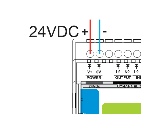
🔌 24 VDC Logic Power
Connect regulated 24 VDC (SELV) to the top‑left POWER terminals V+ and 0V.
This powers the MCU, LEDs, USB‑C (setup), and RS‑485 interface.
🔘 Digital Inputs (DI1–DI4)
Wire dry‑contact switches to the opto‑isolated inputs.
Each input has its own paired Gnd and must be wired independently.
Input mode (Momentary/Latching), debounce, invert, and press‑logic are set in WebConfig.
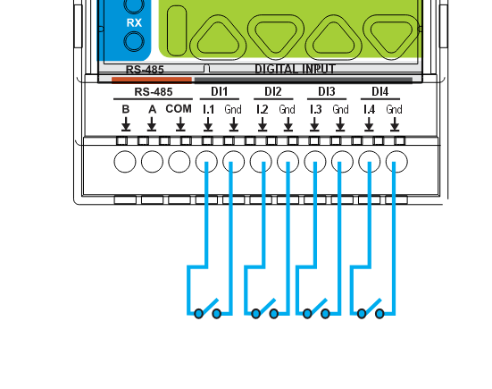
Tip: keep DI wiring separate from mains cabling and provide strain relief.
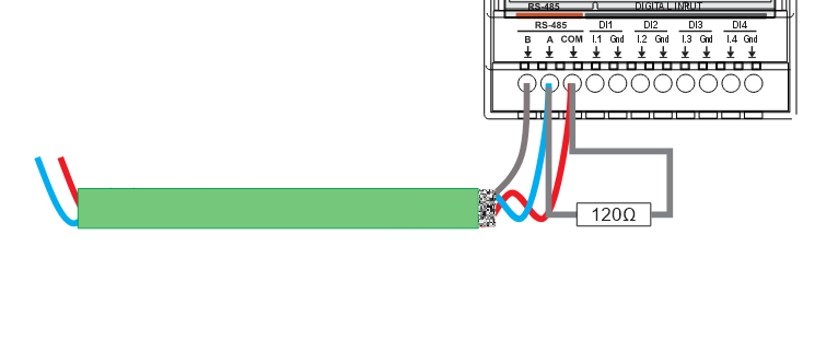
🧷 RS‑485 (Modbus RTU)
Bottom‑left terminals are labeled B A COM (as on the front panel).
- B / A → RS‑485 differential pair (use shielded twisted pair)
- COM → optional reference ground to the controller
- Terminate the bus at both ends (~120 Ω) if not already present
- Defaults: Slave ID 3, 19200 baud, 8N1 (change in WebConfig)
🧰 USB‑C Port (Front)
For setup/diagnostics only:
- In‑browser WebConfig over Web Serial (Chromium‑based browsers)
- Firmware updates via UF2 bootloader
Disconnect USB‑C after commissioning; use RS‑485 for runtime control.
4.5 Software & UI Configuration
You can configure the DIM‑420‑R1 entirely from a Chromium browser using Web Serial. No drivers or apps required.
🔗 Online WebConfig:
https://www.home-master.eu/configtool-dim-420-r1
🖥 Browser & Cable
- Use a Chromium‑based browser (Chrome / Edge / Brave).
- Connect a USB‑C cable to the module.
- Power the module with 24 VDC (USB only provides data).
🔗 Modbus Connection
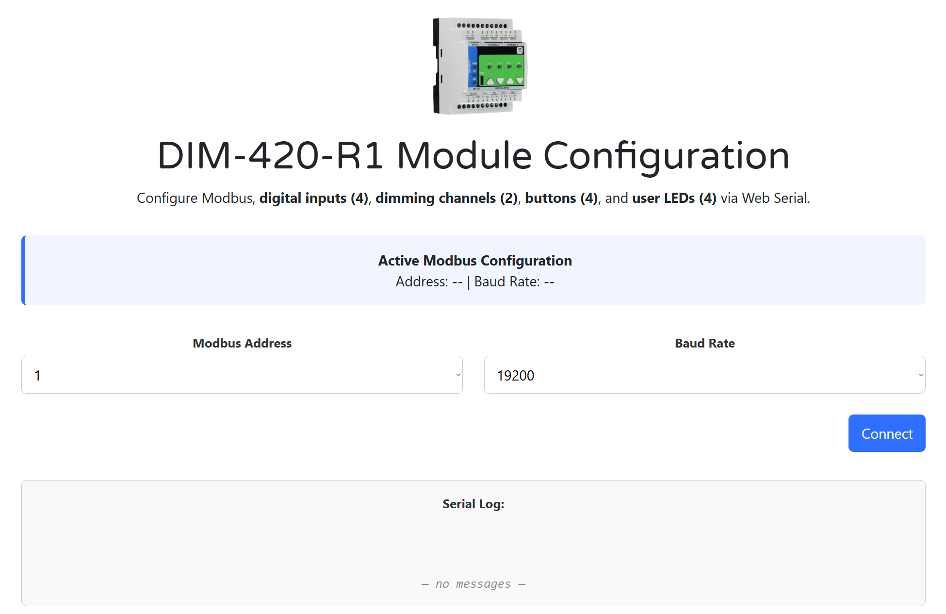
- Open the WebConfig tool from the link above.
- Select the current Modbus Address and Baud Rate.
- Click Connect and allow Serial access.
- The Active Modbus Configuration banner shows detected values.
Default: Slave ID = 3, Baud = 19200, 8N1.
A live Serial Log keeps the last 5 messages for quick feedback.
🎚 Dimming Channels (CH1 & CH2)
Each dimmer channel can be configured for its intended load and behavior:
- AC Presence / Frequency badges confirm input signal quality.
- Load Type: Lamp (log), Heater (linear), or Key (non‑dimmable).
- Cutoff Mode: Leading (RL) or Trailing (RC).
- Lower/Upper Thresholds: Clamp range for reliable dimming.
- Preset Level: Value used when toggle/on events occur.
- Percent Slider: Sends live target; UI reflects actual level (0–255).
Changes apply instantly and persist to flash ~1.5s after the last edit.
🟢 Digital Inputs (DI1–DI4)
Configure press logic, target channels, and press actions:
- Input mode: Momentary or Latching
- Mappable press types: Short, Long, Double, Short‑then‑Long
- Actions: Turn on/off, Toggle, Ramp, Go to MAX, Ping‑pong
Each DI has its own mapping per event and an optional invert.
🔘 Buttons & LEDs
Configure onboard pushbuttons and indicator LEDs:
- Buttons: Trigger actions like Toggle CH1, Ramp up/down, MAX preset.
- LEDs: Mode (Steady / Blink) and Source (Channel or None).
Button presses are de‑bounced and detected in firmware. LED states are updated live.
💾 Save & Restore
- Config is stored automatically in flash after changes.
- Settings persist through power loss and reset.
If Connect is greyed out: check USB cable, browser support (Chrome/Edge), and Serial permissions.
5. DIM‑420‑R1 — Technical Specification
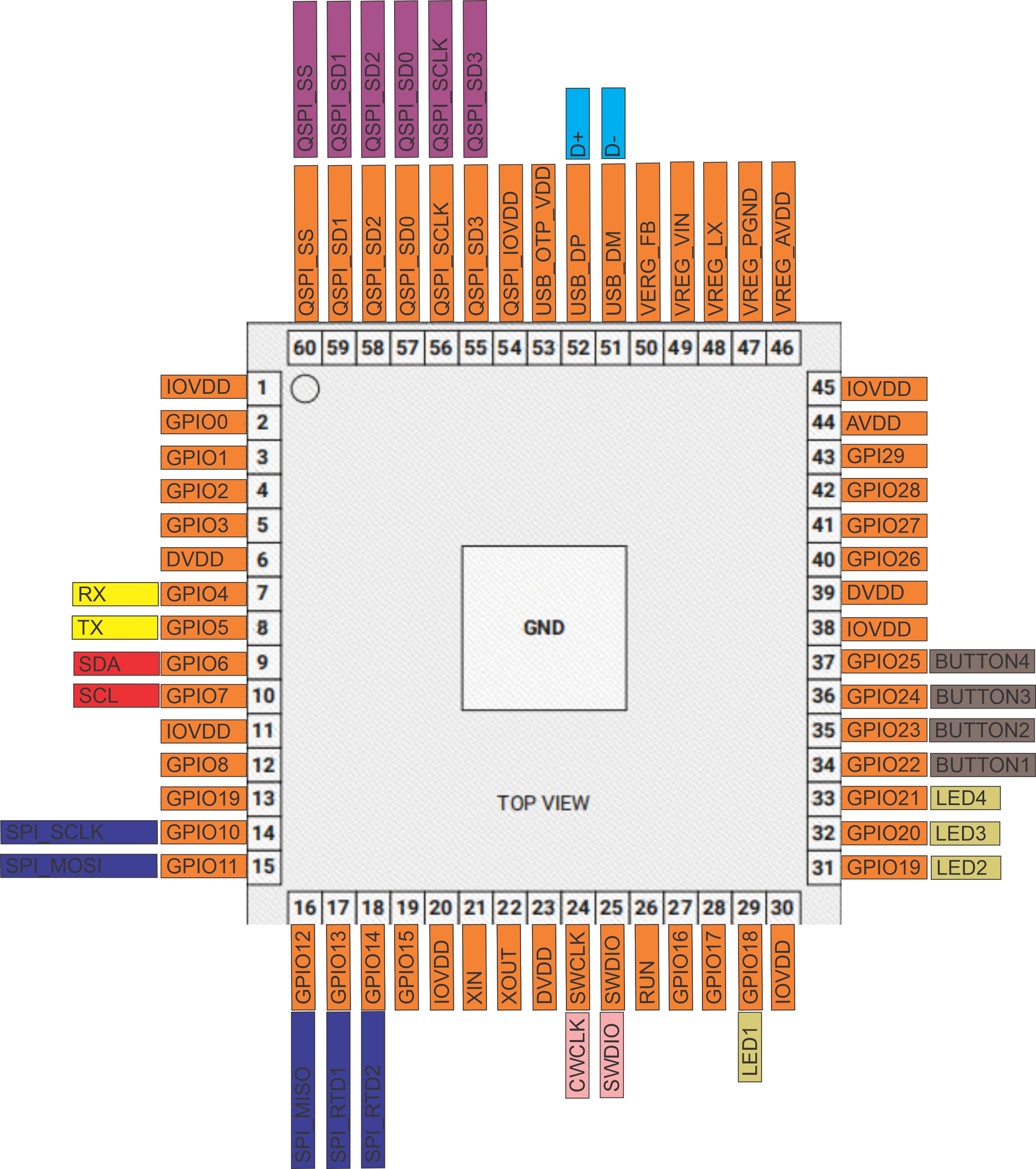
5.1 Diagrams & Pinouts
| System Block Diagram | MCU Pinout |
|---|---|
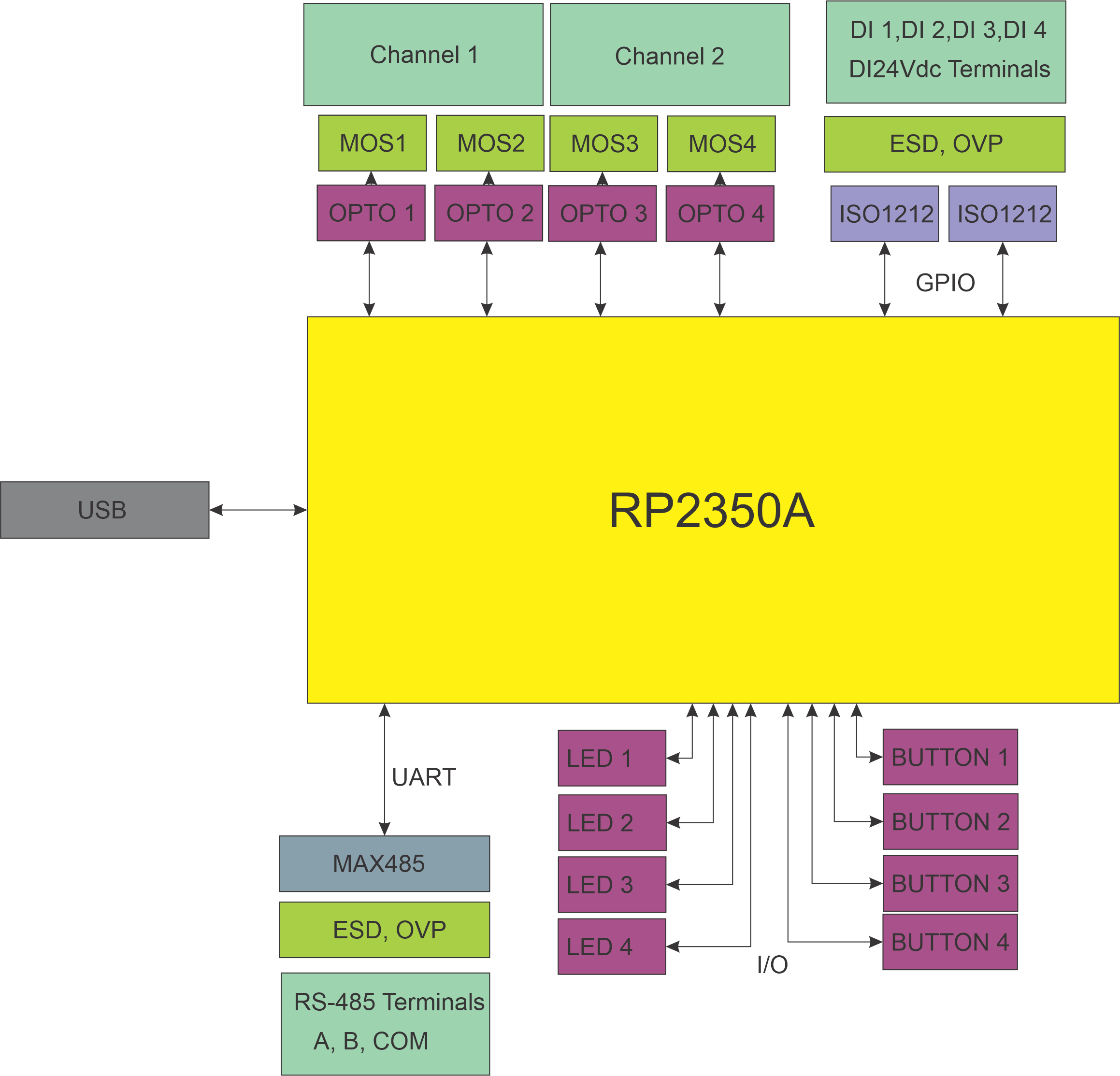 |
 |
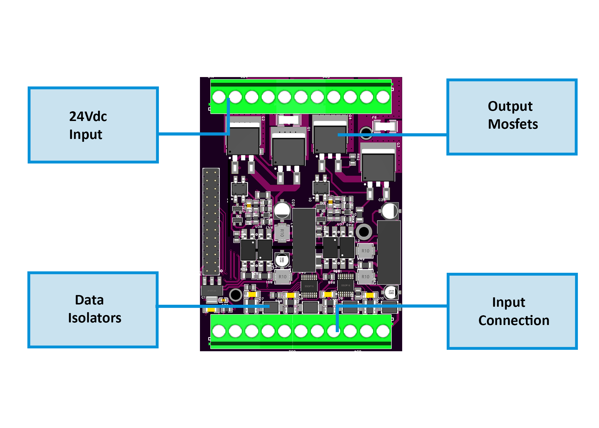
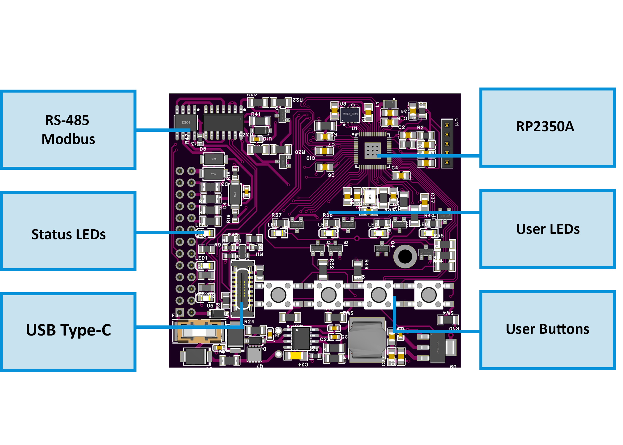
| Field Board Layout | MCU Board Layout |
|---|---|
 |
 |
5.2 I/O Summary
| Interface | Qty | Description |
|---|---|---|
| Digital Inputs | 4 | Opto-isolated sourcing inputs, surge-protected |
| Dimming Outputs | 2 | Phase-cut AC outputs (MOSFET, Leading/Trailing) |
| User Buttons | 4 | Local override / toggle / ramp / preset actions |
| User LEDs | 4 | Configurable (CH state, AC presence, DI state) |
| RS‑485 Bus | 1 | Modbus RTU slave (A/B/COM) |
| USB‑C Port | 1 | Configuration & firmware via Web Serial (USB) |
| Relays | 0 | Not present (uses solid-state AC dimming) |
5.3 Electrical Specifications
| Parameter | Value |
|---|---|
| Supply Voltage (V+) | 24 VDC ±10% SELV |
| Power Consumption | Typ. 1.85 W / Max. 3 W |
| Logic Rails | 5 V (Buck), 3.3 V (LDO) |
| Isolated Power Rails | +5V_ISO1 / +5V_ISO2 |
| Dimming Outputs | 110/230 VAC, Leading/Trailing |
| DI Input Threshold | 24 VDC, opto-isolated (ISO1212) |
| USB-C Function | Web Serial + UF2 upload |
| RS-485 Interface | 115.2 kbps max, Modbus RTU |
| Temperature Range | 0…+40 °C |
| Humidity Range | ≤ 95 % RH, non-condensing |
⚠ Installer note: Fuse 24 VDC input externally; protect AC loads per local code.
5.4 Terminal Map
All terminals are 5.08 mm pitch, 300 V / 20 A rated, 26–12 AWG.
| Group | Terminals | Description / Notes |
|---|---|---|
| POWER | V+, 0V | Logic power (24 VDC SELV) |
| DI | DI1–DI4 + GND pairs | Opto-isolated inputs; each has dedicated GND |
| AC OUT | Lx_IN/OUT, Nx_IN/OUT | Dimmed output channels (CH1/CH2) |
| RS‑485 | A, B, COM | Differential bus + optional ground ref |
| USB-C | Front panel USB-C port | For setup only (Web Serial & UF2) |

5.5 Absolute Electrical Specifications
| Parameter | Min | Typ | Max | Notes |
|---|---|---|---|---|
| Supply voltage (V+) | 20 V | 24 V | 30 V | SELV; reverse polarity protected |
| Power consumption | – | 1.85 W | 3 W | Logic only (no load) |
| Logic rails | – | 5 V / 3.3 V | – | Buck + LDO derived |
| Isolated rails | +5V_ISO1/2 | – | – | Internal use for dimmer stage only |
| Digital inputs | – | – | 24 VDC | ISO1212 front-end, protected |
| AC dimmer outputs | – | – | 110/230 VAC | 2× WMM36N65C4 (MOSFET) |
| RS-485 Interface | – | – | 115.2 kbps | TVS/ESD + fail-safe |
| USB-C (setup only) | 5 V | – | – | |
| Ambient temperature | 0 °C | – | +40 °C | 32–104 °F |
| Humidity (operating) | – | – | 95 %RH | Non-condensing |
5.6 Protection Features
-
24 V Input
- Diode reversed path
- TVS: SMBJ33A
- High-side P-MOS + fuse (F1206HI8000V024TM)
-
DI Channels
- ISO1212 opto-isolated front end
- PTC: 1206L016WR
- TVS: SMBJ26CA
-
Dimmer Stage
- Power switches: WMM36N65C4, 650 V
- Isolation: SFH6156‑3T optocouplers
- Input bridge: MB6S
- Zero-cross & snubber integrated
-
RS‑485
- Transceiver: MAX485
- TVS: SMAJ6.8CA
- Pull-up/down: 4.7 kΩ bias
- Termination pads included
-
USB-C
- USB-UART: RP2350
- ESD Clamp: PRTR5V0U2X
- Data-line resistors: 27 Ω
5.7 Mechanical
| Attribute | Value |
|---|---|
| Mounting | DIN rail (EN50022, 35 mm) |
| Material | PC/ABS, UL V-0 |
| Color / Finish | Light Gray / Smoke, Matte |
| Dimensions (L×W×H) | 157.4 × 91 × 58.4 mm |
| Division Units | 9M |
| Net Weight | 420 g |
| Terminal Specs | 26–12 AWG, 0.5–0.6 Nm torque |
5.8 Environmental & Compliance
| Parameter | Value |
|---|---|
| Operating Temp | 0 °C … +40 °C |
| Operating Humidity | ≤ 95 % RH, non-condensing |
| Ingress Protection | IP20 |
| Pollution Degree | 2 |
| Impulse Voltage | 2.5 kV (UL60730-1) |
| Operation Class | Type 1 (UL60730-1, CSA E60730-1) |
| Altitude Rating | ≤ 2000 m |
| Certifications | CE, UL60730-1, CSA E60730-1 |
| RoHS / Pb-free | ✅ Compliant |
6. Modbus RTU Communication
The DIM‑420‑R1 communicates via Modbus RTU over RS‑485 as a slave device, polled by a PLC, SCADA, or ESPHome-based controller. It exposes discrete inputs, coils, and holding registers for full control and monitoring of the module.
6.1 Default Communication Settings
| Parameter | Default |
|---|---|
| Slave ID | 3 |
| Baud Rate | 19200 |
| Framing | 8N1 |
| Protocol | Modbus RTU |
| Port | RS‑485 (A/B/COM) |
| Change via | USB-C WebConfig |
6.2 Address Map
The following Modbus function codes are used:
- FC01 / FC05 — Coils (write-triggered actions)
- FC02 — Discrete Inputs (status flags)
- FC03 / FC06 / FC16 — Holding Registers (configuration + real-time control)
6.3 Discrete Inputs (FC02)
| Addr | Name | Description |
|---|---|---|
| 1–4 | DI1–DI4 | Digital input state (debounced, inverted) |
| 50 | CH1_ON | CH1 active (enabled + Level > 0) |
| 51 | CH2_ON | CH2 active |
| 90–93 | LED1–LED4 | Current physical LED output state |
| 120 | ZC1_OK | Zero-cross detected on CH1 AC input |
| 121 | ZC2_OK | Zero-cross detected on CH2 AC input |
6.4 Coils (FC01 / FC05)
Coils are momentary triggers. Write 1 to trigger; auto-resets to 0.
| Addr | Action |
|---|---|
| 200 | CH1 ON (to Preset) |
| 201 | CH2 ON (to Preset) |
| 210 | CH1 OFF |
| 211 | CH2 OFF |
| 300–303 | DI1…DI4 ENABLE |
| 320–323 | DI1…DI4 DISABLE |
6.5 Holding Registers (FC03 / FC06 / FC16)
| Addr (CH1/CH2) | Name | Range / Type | Description |
|---|---|---|---|
| 400 / 401 | Level | 0–255 (U8) | Output level (0 = OFF) |
| 410 / 411 | Lower | 0–255 (U8) | Minimum level to light the load |
| 420 / 421 | Upper | 0–255 (U8) | Maximum level |
| 430 / 431 | Freq_x100 | Hz×100 (RO) | Measured AC mains frequency |
| 440 / 441 | Percent×10 | 0–1000 (U16) | Target dimming percent ×10 |
| 460 / 461 | LoadType | 0=Lamp, 1=Heater, 2=Key | Affects mapping and logic |
| 470 / 471 | CutMode | 0=Leading, 1=Trailing | Phase-cut mode |
| 480 / 481 | Preset | 0–255 | Value used by CH ON coil |
Writing Percent×10 immediately recalculates and applies Level based on LoadType, Lower/Upper limits.
6.6 Register Usage Examples
| Operation | Write To / Read From |
|---|---|
| Turn CH1 ON | Coil 200 ← 1 |
| Set CH2 OFF | Coil 211 ← 1 |
| Set CH1 to 50% | Reg 440 ← 500 |
| Change CH2 to Trailing edge | Reg 471 ← 1 |
| Clamp CH1 Level (e.g. 25–200) | Reg 410 ← 25, 420 ← 200 |
| Disable DI3 | Coil 322 ← 1 |
| Enable DI3 | Coil 302 ← 1 |
6.7 Polling Recommendations
- Interval: 500–1000 ms recommended for discrete input/holding register polling
- Write timing: Momentary coils are safe to write every 1–2 seconds max
- Avoid flooding: Do not poll coils or write continuously at high speed
- Sync strategy: Read current Level before changing Percent to avoid flicker
6.8 Additional Notes
- All config/state is mirrored over Modbus and Web Serial snapshot
- Modbus address and baud rate are editable via USB-C (WebConfig)
- Disabling a DI via coil makes its press events inert until re-enabled
7. ESPHome Integration Guide
The DIM‑420‑R1 integrates natively with ESPHome and Home Assistant via Modbus RTU using a plug-and-play YAML package.
No local logic is required — all channel control, DI events, LEDs, and feedback are exposed as entities.
7.1 Installation via packages: Block
Add the DIM‑420‑R1 using the official GitHub YAML:
packages:
  dim1:
    url: https://github.com/isystemsautomation/HOMEMASTER
    ref: main
    files:
      - path: DIM-420-R1/Firmware/default_dim_420_r1_plc/default_dim_420_r1_plc.yaml
        vars:
          dim_prefix: "DIM#1"
          dim_id: dim_1
          dim_address: 5
    refresh: 1d
Replace
dim_addresswith the actual Modbus ID of your device.
dim_prefixcontrols the name of entities in Home Assistant (e.g.,DIM#1 CH1 Level).
7.2 Required UART/Modbus Setup
Add this to your configuration.yaml if not using a package:
uart:
  tx_pin: 17
  rx_pin: 16
  baud_rate: 19200

modbus:
  id: modbus_bus
The DIM‑420‑R1 supports 9600–115200 baud. Defaults to 19200/8N1/ID 3.
7.3 Exposed Entities (Per Package)
| Entity Type | Description |
|---|---|
switch: |
CH1/CH2 ON triggers (momentary) |
number: |
Level, Lower, Upper, Preset, Percent |
select: |
Cut Mode, Load Type |
binary_sensor: |
DI1–DI4, ZC1 OK, ZC2 OK, CH1/CH2 ON, LEDs |
Example:
DIM#1 CH1 On(switch) → writes coil 200DIM#1 CH1 Percent(number) → writes register 440DIM#1 DI1(binary_sensor) → maps discrete input 1DIM#1 LED1(binary_sensor) → LED status from Modbus
7.4 Override & Acknowledge Actions
The included YAML handles:
- Ramp via
button:components (step up/down) - Preset recall via
switch:(CH ON) - DI disable/enable via modbus write
- Button logic via controller or mapped automation
Use the
on_turn_on:+delay:+switch.turn_off:pattern for all momentary actions (e.g., toggles).
7.5 Home Assistant Tips
- Device classification is already embedded in the package
- Add
device_class: lightto numeric outputs if desired - Use ESPHome's
deltafilters to prevent value flooding - Use
entity_id: contains "DIM#1"for dashboard grouping - All sensors/entities are safe to publish with
on_value:logic
8. Programming & Customization
8.1 Supported Languages
- Arduino / PlatformIO
- C++ (direct RP2040 SDK)
- (MicroPython partially supported, but not recommended for precise dimming)
8.2 Flashing the Module
The DIM‑420‑R1 includes a USB‑C interface for:
- WebConfig diagnostics
- Firmware updates via UF2
- Serial flashing via Arduino IDE / PlatformIO
🔌 UF2 Drag-and-Drop Method
- Hold Button 1 + Button 2
- Connect USB-C
- A drive named
RPI-RP2will appear - Drag your
firmware.uf2into it - Device reboots into normal mode
🔧 Flash via Arduino or PlatformIO
- Connect USB-C
- Optional: press Reset (or hold U3+U4 for hard reset)
- Upload via selected COM port
Button Mapping (Front Panel)
| Button | Label | Default Function | Special Use |
|---|---|---|---|
| 1 | U.1 | Action 1 | Hold with U.2 → Enter BOOT/UF2 mode |
| 2 | U.2 | Action 2 | Paired with U.1 |
| 3 | U.3 | Action 3 | Hold with U.4 → Reset to firmware |
| 4 | U.4 | Action 4 | Paired with U.3 |
8.3 Arduino / PlatformIO Notes
🔌 Required Libraries
#include
#include
#include
#include
#include
#include
#include
#include "pico/time.h" // time_us_64(), add_alarm_in_us(), alarm_id_t
9. Maintenance & Troubleshooting
🟢 LED Status
| LED | Meaning |
|---|---|
| PWR | Steady = Power OK |
| TX | Blinks = Sending Modbus |
| RX | Blinks = Receiving Modbus |
| U.1–U.4 | Firmware-controlled |
🧰 Common Issues
| Symptom | Fix / Tip |
|---|---|
| No RS‑485 Comms | Check A/B polarity, Slave ID, baud |
| LED not working | Confirm LED source and mode in WebConfig |
| DI not detected | Use correct GND pair and debounce logic |
| No USB detection | Close all serial monitors; |
| CH not dimming | Check ZC presence, Cut Mode, Lower/Upper |
10. Open Source & Licensing
- Hardware: CERN-OHL-W v2.0
- Firmware: GNU GPLv3
All repositories are publicly available at:
🔗 https://github.com/isystemsautomation/HOMEMASTER/tree/main/DIM-420-R1
11. Downloads
| Item | Link |
|---|---|
| Firmware Source | /Firmware/default_DIM_420_R1 |
| ESPHome Config | default_dim_420_r1_plc.yaml |
| WebConfig Tool | Online Version |
| Schematics (PDF) | /Schematics |
| Mechanical Images | See /Images/ in repo |
| Datasheet | DIM-420-R1.pdf |
12. Support
Need help using, wiring, or flashing the DIM‑420‑R1? Try these:
- 💼 Official Support Portal
- 🔧 WebConfig Tool
- 🎥 YouTube Tutorials
- 💬 Reddit Community
- 🧪 Hackster Projects
Or open an issue on GitHub if you're a developer or tester.
🚧 Project Status: Under Active Development & Testing
Important Notice: This documentation, hardware designs, and firmware are for the pre-release version of the HomeMaster system. All information is preliminary and may contain errors or be subject to change.
- Hardware: Modules are currently in the prototyping and testing phase. Final production versions may differ.
- Firmware: Firmware is under active development and is considered beta. Features, configurations, and stability are being refined.
Please use this information for evaluation and development purposes only.
1. Introduction
1.1 Overview of the DIM-420-R1 Module ✨
The DIM‑420‑R1 is a modular dimmer I/O device for dual‑channel phase‑cut AC dimming in the HomeMaster MicroPLC / MiniPLC ecosystem. It exposes 2 dimming channels, 4 isolated digital inputs, 4 configurable user buttons, 4 user LEDs, and an RS‑485 Modbus RTU interface. Setup and diagnostics are performed in‑browser via WebConfig over USB‑C (Web Serial)—no special software required.
It integrates seamlessly with MiniPLC / MicroPLC controllers, third‑party Modbus masters, ESPHome / Home Assistant, and SCADA/PLC systems. Typical use: connect wall switches to the DIs, pick Leading/Trailing edge per load, set Lower/Upper thresholds, and control scenes from a PLC or locally with press‑logic.
Quick use case:
Wire DI1–DI4 to wall switches → select Momentary or Latching with Short/Long/Double logic → choose Cut Mode and Load Type per channel → map LEDs/Buttons → connect RS‑485 A/B → control and monitor via PLC / ESPHome.
1.2 Features & Architecture
Core Capabilities
| Subsystem | Qty | Description |
|---|---|---|
| Digital Inputs | 4 | isolated dry‑contact inputs (ISO1212 front‑end); modes: Momentary/Latching with Short / Long / Double / Short‑then‑Long press types. Debounced and firmware‑interpreted for actions. |
| Dimming Outputs | 2 | MOSFET‑based phase‑cut AC outputs; Leading/Trailing per channel with Lower/Upper threshold limits and zero‑cross sync/monitoring. |
| Relays | 0 | – |
| User LEDs | 4 | Steady/Blink; sources: CH1/CH2 state, DI1–DI4, or AC presence (ZC OK). |
| User Buttons | 4 | Local acknowledge/override; firmware press‑logic for toggle, ramp (ping‑pong), preset, max. |
| Config UI | Web Serial | WebConfig in Chromium browser over USB‑C; edit Modbus addr/baud, thresholds, cut mode, presets; live log & JSON snapshot. |
| Modbus RTU | RS‑485 | Multi‑drop slave; FC01/05/02/03/06/16 with discrete inputs, coils, and holding registers. Defaults ID=3, 19200, 8N1. |
| MCU | RP2350A | Dual‑core MCU; QSPI flash for firmware/config; Arduino/PlatformIO supported. |
| Power | 24 VDC | Protected 24 V input; on‑board isolated 5 V rails for power stages (B2405S‑2WR3) and local 3.3 V regulation. |
| Protection | TVS, PTC | Surge/ESD protection and resettable fuses on field I/O and RS‑485/USB/power paths. |
1.3 System Role & Communication 🔌
The DIM‑420‑R1 is a standalone Modbus RTU slave on an RS‑485 multi‑drop trunk. It executes local input press‑logic and dimming behavior, mirrors state to discrete inputs/holding registers, and accepts control via coils/holding writes from a master (PLC/SCADA/ESPHome). A live JSON snapshot and event log stream over Web Serial for commissioning and diagnostics.
| Role | Description |
|---|---|
| System Position | Expansion/field module on RS‑485 bus (A/B/COM). |
| Master Controller | MiniPLC / MicroPLC or any third‑party Modbus RTU master. |
| Address / Baud | Configurable via WebConfig; default Slave ID = 3, 19200 baud, 8N1 (persisted to flash). |
| Bus Type | RS‑485 multi‑drop with proper termination and biasing. |
| USB‑C Port | Setup/diagnostics, UF2 firmware updates via RP2350 bootloader; in‑browser WebConfig. |
| Polling Model | Master polls DI/LED/AC status and writes coils/registers for ON/OFF, presets, levels, and config. |
⚠️ Note: If multiple DIM‑420‑R1 modules share the same RS‑485 line, assign unique Modbus IDs in WebConfig and verify termination/bias.
2. Use Cases
Scene Control with Wall Switches
Control dimmed lighting scenes using standard wall switches wired to the digital inputs.
- Short press toggles CH1 to preset.
- Long press ramps CH1 up or down.
- Double press sets CH2 to max.
Setup Instructions:
- Wire DI1–DI4 to wall pushbuttons.
- In WebConfig → set DI1: Momentary.
- Map actions:
- Short → Toggle CH1
- Long → Increase CH1
- DoubleShort → Go Max CH2
- Set CH1 preset = 180 and CH2 upper threshold = 255.
- Save configuration and test with physical input.
3. Safety Information
These guidelines apply to the DIM‑420‑R1 dimmer module. Ignoring them may result in equipment damage, electric shock, or fire.
⚠️ Mixed‑voltage device — The module contains both SELV/PELV control electronics and hazardous AC mains on the dimmer channels (
Lx_IN/Lx_OUT,Nx_IN/Nx_OUT). The logic side is galvanically isolated (opto + isolated 5 V rails), but mains is present on the power section and output terminals. Handle as a mains device.
3.1 General Requirements
| Requirement | Detail |
|---|---|
| Qualified Personnel | Installation and servicing by trained technicians only (panel wiring + mains safety). |
| Power Isolation | Isolate both 24 VDC and AC mains before touching wiring or terminals (lockout/tagout). |
| Environmental Limits | Mount inside a dry, clean, ventilated enclosure; avoid condensation, conductive dust, vibration. |
| Grounding | Bond the control panel to protective earth. Keep SELV grounds and mains earth/neutral managed per code. |
| Voltage Domains | Treat +5V_ISO1/ISO2, GND_ISO1/ISO2 and L/N terminals as mains domain; do not bridge to logic GND. |
3.2 Installation Practices
| Task | Guidance |
|---|---|
| ESD Handling | Handle PCBs by the edges; use antistatic strap and grounded work surface. |
| DIN Mounting | Secure on 35 mm DIN rail inside an enclosure; provide strain relief on all cables. |
| Isolation Domains | Respect isolation: logic (24 V, RS‑485, USB) vs. power side (AC L/N, isolated 5 V rails). Never tie GND to GND_ISO1/2. |
| AC Load Wiring | Use proper gauge; route mains L/N to Lx_IN/Nx_IN and load to Lx_OUT/Nx_OUT. Keep AC wiring segregated from SELV cabling. |
| Cut‑Mode Selection | Choose Leading/Trailing to match lamp/driver; verify Lower/Upper thresholds to prevent flicker. |
| Over‑current Protection | Provide upstream MCB/RCD per load and locale. Use external snubbers only if required by the load. |
| Commissioning | With mains OFF: verify RS‑485 A/B polarity, DI logic, and LED/Button mapping. Power on with no load first, then connect loads and test gradually. |
3.3 I/O & Interface Warnings
Power
| Area | Warning |
|---|---|
| 24 VDC Input | Use a clean SELV 24 VDC source; observe polarity. Protected by fuses/TVS and buck → 5 V/3.3 V regulators. |
| Isolated Rails | +5V_ISO1/ISO2 feed the dimmer power stages; they belong to the mains domain. Do not use for external sensors. |
Inputs (SELV)
| Area | Warning |
|---|---|
| DI1–DI4 | Dry contacts / isolated low‑voltage only (isolated front end). Do not apply mains. Use DIx_GND returns and configure debounce/invert in UI. |
Dimming Channels (MAINS)
| Area | Warning |
|---|---|
| CH1 / CH2 AC Terminals | Lx_IN/Lx_OUT, Nx_IN/Nx_OUT carry hazardous mains. Use appropriate insulation, creepage/clearance, and enclosure practices. Components include HV MOSFETs (650 V class) and opto interfaces. |
| Load Types | Use loads compatible with selected Leading/Trailing edge. Many LED drivers require Trailing; check the datasheet. |
| Snubbers/EMI | Internal suppression is provided in the power stage; add external RC snubbers only if the load manufacturer requires it. Keep mains wiring short and twisted where possible. |
Communication & USB (SELV)
| Area | Warning |
|---|---|
| RS‑485 (A/B/COM) | Use twisted pair (shielded). Terminate at bus ends (≈120 Ω). Maintain SELV separation from AC wiring. |
| USB‑C (setup only) | For configuration/UF2 only. Avoid connecting a PC to the USB port while panels are open and mains wiring is exposed; mind ground loops. |
✅ Pre‑Power Checklist
- All AC and SELV cables are routed separately with strain relief.
- No bridges between logic GND and GND_ISO1/2; isolation gaps unobstructed.
- RS‑485 polarity/termination verified; DI wiring and logic mode match configuration.
- Cut Mode and Lower/Upper thresholds set per lamp/driver datasheet; start with light loads.
- Upstream MCB/RCD sized for the load; enclosure closed before applying mains.
4. Installation & Quick Start
The DIM‑420‑R1 is a smart dual-channel dimmer with Modbus RTU and onboard USB‑C WebConfig. Setup has two main stages:
- Wiring & power (24 V + RS‑485 + AC load)
- Digital configuration (WebConfig → Modbus ID, Cut Mode, etc.)
4.1 What You Need
| Category | Item | Details |
|---|---|---|
| Hardware | DIM‑420‑R1 | DIN-rail dimmer with 2 AC outputs, 4 DIs, 4 buttons, 4 LEDs, USB‑C, RS‑485 |
| Controller (master) | HomeMaster MiniPLC / MicroPLC or any Modbus RTU master | |
| 24 VDC PSU (SELV) | Regulated 24 VDC to V+ / 0V (logic + UI). AC loads powered separately. |
|
| RS‑485 Cable | Twisted pair (shielded). Use A/B/COM, terminate with 120 Ω if needed. |
|
| USB‑C cable | For WebConfig via Chromium browser (setup only) | |
| Software | WebConfig (built-in) | Open ConfigToolPage.html in a Chromium browser |
| PLC/HA YAML (optional) | For ESPHome/Home Assistant: exposes CH/DI/LED control | |
| Field I/O | AC Load | CH1/CH2 outputs to trailing- or leading-edge dimmable loads |
| DI Switches | Wall switches (dry contact). Use DIx + GND. Momentary/latching supported. |
|
| RS‑485 bus | A / B / COM (use shielded twisted pair). COM is optional GND ref | |
| Power Terminals | V+, 0V = logic power (SELV). Lx/Nx IN/OUT = mains side. |
💡 Quick path mount: wire 24 VDC, RS‑485 (A/B/COM), and DI → connect USB‑C → open WebConfig → set Modbus & cut mode → tune thresholds → map DIs/LEDs → save → disconnect USB → go live.
4.2 Power
The DIM‑420‑R1 uses 24 VDC SELV for logic, UI, RS‑485, and Web Serial.
AC power is handled separately by the dimming channels (see §4.4).
🔌 Supply Details
| Type | Description |
|---|---|
| 24 VDC Input | Primary logic power. Connect V+ / 0V. Protected by fuse + TVS. |
| AC Power | CH1/CH2 output sections are powered via Lx_IN/Nx_IN terminals. Do not share logic power and AC domains. |
| Internal Rails | Onboard 5 V + 3.3 V (buck-regulated) for logic, UI, and isolated side. |
⚡ Current
- ~50 mA idle (logic + UI only)
- Add budget if using all 4 LEDs, buttons, and rapid RS‑485 comms.
- AC loads pull from separate mains lines — never through the 24 V rail.
4.3 Networking & Communication
DIM‑420‑R1 supports RS‑485 Modbus RTU for runtime control and USB‑C WebConfig for setup.
4.3.1 RS‑485 (Modbus RTU)
🧷 Terminals
A B COM
Located bottom-left on module:
| Pin | Description |
|---|---|
| A / B | RS‑485 differential pair |
| COM | Optional GND reference (connect to controller GND if needed) |
Use shielded twisted pair, terminate at both ends (~120 Ω), and bias if required.
🔁 Protocol
| Parameter | Value |
|---|---|
| Role | Slave (DIM‑420‑R1) |
| Address Range | 1–247 (default = 3) |
| Baud | 9600–115200 (default = 19200) |
| Format | 8 data bits, No parity, 1 stop bit (8N1) |
4.3.2 USB‑C (WebConfig)
For setup/diagnostics via Chromium:
🖥 Steps
- Connect USB‑C to PC
- Open
ConfigToolPage.html(local or hosted) - Click Connect (Web Serial)
- Set:
- Modbus Address & Baud
- Channel Cut Mode (Leading/Trailing)
- Lower/Upper thresholds
- Input mode: Momentary/Latching
- Map LEDs / Buttons
- Click Save
- Disconnect USB → RS‑485 master takes over
🔐 If Connect is disabled, ensure you're using Chromium + USB permission is granted. On macOS/Linux, close any app that may be holding the port (e.g., serial monitor).
Let me know if you'd like the follow-up section 4.4 Wiring Examples or 5 Controller Integration.
4.4 Installation & Wiring
The DIM‑420‑R1 separates low‑voltage logic (24 VDC, RS‑485, USB‑C, DIs) from mains‑side dimmer outputs (L/N IN/OUT). Use the visuals below when wiring.
🔌 24 VDC Logic Power
Connect regulated 24 VDC (SELV) to the top‑left POWER terminals V+ and 0V.
This powers the MCU, LEDs, USB‑C (setup), and RS‑485 interface.
🔘 Digital Inputs (DI1–DI4)
Wire dry‑contact switches to the opto‑isolated inputs.
Each input has its own paired Gnd and must be wired independently.
Input mode (Momentary/Latching), debounce, invert, and press‑logic are set in WebConfig.
Tip: keep DI wiring separate from mains cabling and provide strain relief.
🧷 RS‑485 (Modbus RTU)
Bottom‑left terminals are labeled B A COM (as on the front panel).
- B / A → RS‑485 differential pair (use shielded twisted pair)
- COM → optional reference ground to the controller
- Terminate the bus at both ends (~120 Ω) if not already present
- Defaults: Slave ID 3, 19200 baud, 8N1 (change in WebConfig)
🧰 USB‑C Port (Front)
For setup/diagnostics only:
- In‑browser WebConfig over Web Serial (Chromium‑based browsers)
- Firmware updates via UF2 bootloader
Disconnect USB‑C after commissioning; use RS‑485 for runtime control.
4.5 Software & UI Configuration
You can configure the DIM‑420‑R1 entirely from a Chromium browser using Web Serial. No drivers or apps required.
🔗 Online WebConfig:
https://www.home-master.eu/configtool-dim-420-r1
🖥 Browser & Cable
- Use a Chromium‑based browser (Chrome / Edge / Brave).
- Connect a USB‑C cable to the module.
- Power the module with 24 VDC (USB only provides data).
🔗 Modbus Connection
- Open the WebConfig tool from the link above.
- Select the current Modbus Address and Baud Rate.
- Click Connect and allow Serial access.
- The Active Modbus Configuration banner shows detected values.
Default: Slave ID = 3, Baud = 19200, 8N1.
A live Serial Log keeps the last 5 messages for quick feedback.
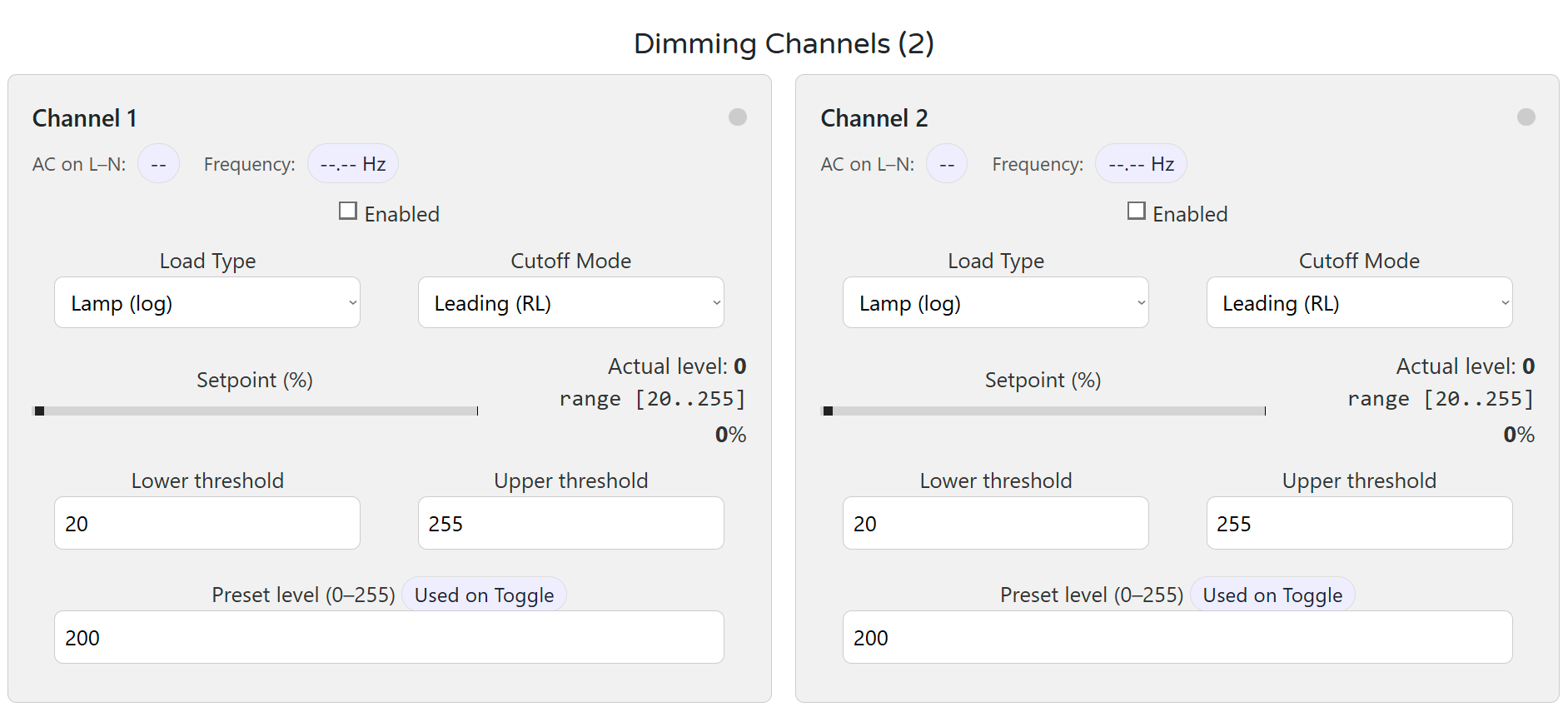
🎚 Dimming Channels (CH1 & CH2)
Each dimmer channel can be configured for its intended load and behavior:
- AC Presence / Frequency badges confirm input signal quality.
- Load Type: Lamp (log), Heater (linear), or Key (non‑dimmable).
- Cutoff Mode: Leading (RL) or Trailing (RC).
- Lower/Upper Thresholds: Clamp range for reliable dimming.
- Preset Level: Value used when toggle/on events occur.
- Percent Slider: Sends live target; UI reflects actual level (0–255).
Changes apply instantly and persist to flash ~1.5s after the last edit.
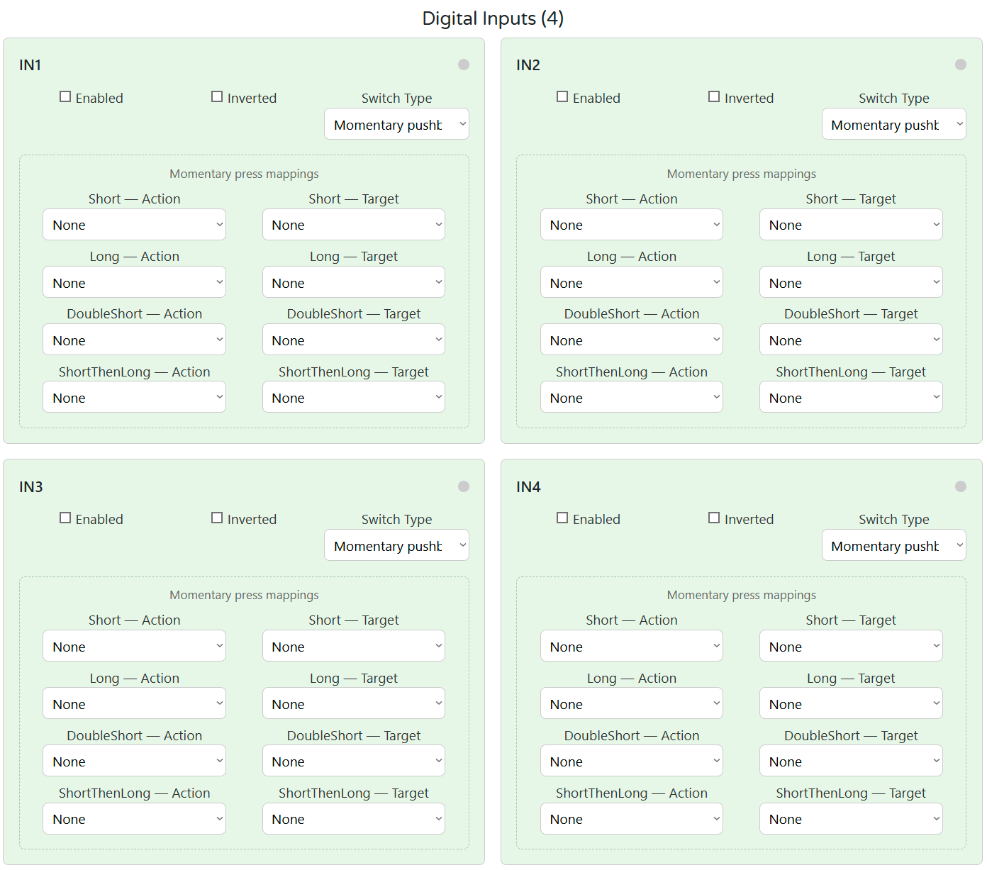
🟢 Digital Inputs (DI1–DI4)
Configure press logic, target channels, and press actions:
- Input mode: Momentary or Latching
- Mappable press types: Short, Long, Double, Short‑then‑Long
- Actions: Turn on/off, Toggle, Ramp, Go to MAX, Ping‑pong
Each DI has its own mapping per event and an optional invert.
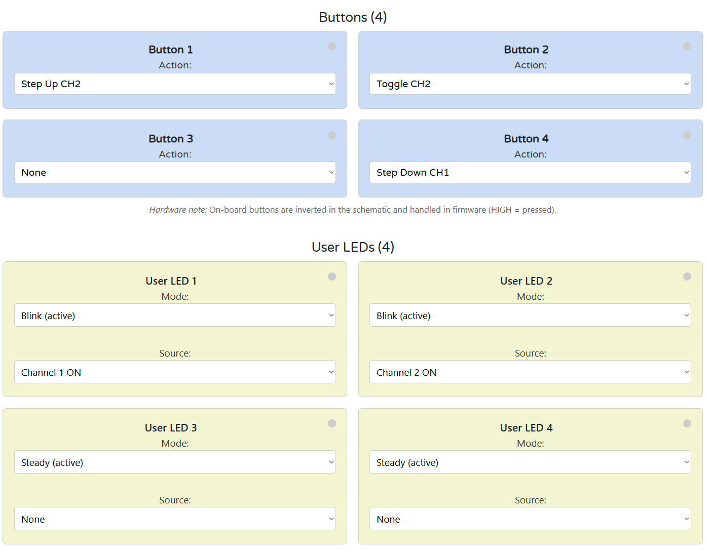
🔘 Buttons & LEDs
Configure onboard pushbuttons and indicator LEDs:
- Buttons: Trigger actions like Toggle CH1, Ramp up/down, MAX preset.
- LEDs: Mode (Steady / Blink) and Source (Channel or None).
Button presses are de‑bounced and detected in firmware. LED states are updated live.
💾 Save & Restore
- Config is stored automatically in flash after changes.
- Settings persist through power loss and reset.
If Connect is greyed out: check USB cable, browser support (Chrome/Edge), and Serial permissions.
5. DIM‑420‑R1 — Technical Specification
5.1 Diagrams & Pinouts
| System Block Diagram | MCU Pinout |
|---|---|
|
|
| Field Board Layout | MCU Board Layout |
|---|---|
|
|
5.2 I/O Summary
| Interface | Qty | Description |
|---|---|---|
| Digital Inputs | 4 | Opto-isolated sourcing inputs, surge-protected |
| Dimming Outputs | 2 | Phase-cut AC outputs (MOSFET, Leading/Trailing) |
| User Buttons | 4 | Local override / toggle / ramp / preset actions |
| User LEDs | 4 | Configurable (CH state, AC presence, DI state) |
| RS‑485 Bus | 1 | Modbus RTU slave (A/B/COM) |
| USB‑C Port | 1 | Configuration & firmware via Web Serial (USB) |
| Relays | 0 | Not present (uses solid-state AC dimming) |
5.3 Electrical Specifications
| Parameter | Value |
|---|---|
| Supply Voltage (V+) | 24 VDC ±10% SELV |
| Power Consumption | Typ. 1.85 W / Max. 3 W |
| Logic Rails | 5 V (Buck), 3.3 V (LDO) |
| Isolated Power Rails | +5V_ISO1 / +5V_ISO2 |
| Dimming Outputs | 110/230 VAC, Leading/Trailing |
| DI Input Threshold | 24 VDC, opto-isolated (ISO1212) |
| USB-C Function | Web Serial + UF2 upload |
| RS-485 Interface | 115.2 kbps max, Modbus RTU |
| Temperature Range | 0…+40 °C |
| Humidity Range | ≤ 95 % RH, non-condensing |
⚠ Installer note: Fuse 24 VDC input externally; protect AC loads per local code.
5.4 Terminal Map
All terminals are 5.08 mm pitch, 300 V / 20 A rated, 26–12 AWG.
| Group | Terminals | Description / Notes |
|---|---|---|
| POWER | V+, 0V | Logic power (24 VDC SELV) |
| DI | DI1–DI4 + GND pairs | Opto-isolated inputs; each has dedicated GND |
| AC OUT | Lx_IN/OUT, Nx_IN/OUT | Dimmed output channels (CH1/CH2) |
| RS‑485 | A, B, COM | Differential bus + optional ground ref |
| USB-C | Front panel USB-C port | For setup only (Web Serial & UF2) |
5.5 Absolute Electrical Specifications
| Parameter | Min | Typ | Max | Notes |
|---|---|---|---|---|
| Supply voltage (V+) | 20 V | 24 V | 30 V | SELV; reverse polarity protected |
| Power consumption | – | 1.85 W | 3 W | Logic only (no load) |
| Logic rails | – | 5 V / 3.3 V | – | Buck + LDO derived |
| Isolated rails | +5V_ISO1/2 | – | – | Internal use for dimmer stage only |
| Digital inputs | – | – | 24 VDC | ISO1212 front-end, protected |
| AC dimmer outputs | – | – | 110/230 VAC | 2× WMM36N65C4 (MOSFET) |
| RS-485 Interface | – | – | 115.2 kbps | TVS/ESD + fail-safe |
| USB-C (setup only) | 5 V | – | – | |
| Ambient temperature | 0 °C | – | +40 °C | 32–104 °F |
| Humidity (operating) | – | – | 95 %RH | Non-condensing |
5.6 Protection Features
-
24 V Input
- Diode reversed path
- TVS: SMBJ33A
- High-side P-MOS + fuse (F1206HI8000V024TM)
-
DI Channels
- ISO1212 opto-isolated front end
- PTC: 1206L016WR
- TVS: SMBJ26CA
-
Dimmer Stage
- Power switches: WMM36N65C4, 650 V
- Isolation: SFH6156‑3T optocouplers
- Input bridge: MB6S
- Zero-cross & snubber integrated
-
RS‑485
- Transceiver: MAX485
- TVS: SMAJ6.8CA
- Pull-up/down: 4.7 kΩ bias
- Termination pads included
-
USB-C
- USB-UART: RP2350
- ESD Clamp: PRTR5V0U2X
- Data-line resistors: 27 Ω
5.7 Mechanical
| Attribute | Value |
|---|---|
| Mounting | DIN rail (EN50022, 35 mm) |
| Material | PC/ABS, UL V-0 |
| Color / Finish | Light Gray / Smoke, Matte |
| Dimensions (L×W×H) | 157.4 × 91 × 58.4 mm |
| Division Units | 9M |
| Net Weight | 420 g |
| Terminal Specs | 26–12 AWG, 0.5–0.6 Nm torque |
5.8 Environmental & Compliance
| Parameter | Value |
|---|---|
| Operating Temp | 0 °C … +40 °C |
| Operating Humidity | ≤ 95 % RH, non-condensing |
| Ingress Protection | IP20 |
| Pollution Degree | 2 |
| Impulse Voltage | 2.5 kV (UL60730-1) |
| Operation Class | Type 1 (UL60730-1, CSA E60730-1) |
| Altitude Rating | ≤ 2000 m |
| Certifications | CE, UL60730-1, CSA E60730-1 |
| RoHS / Pb-free | ✅ Compliant |
6. Modbus RTU Communication
The DIM‑420‑R1 communicates via Modbus RTU over RS‑485 as a slave device, polled by a PLC, SCADA, or ESPHome-based controller. It exposes discrete inputs, coils, and holding registers for full control and monitoring of the module.
6.1 Default Communication Settings
| Parameter | Default |
|---|---|
| Slave ID | 3 |
| Baud Rate | 19200 |
| Framing | 8N1 |
| Protocol | Modbus RTU |
| Port | RS‑485 (A/B/COM) |
| Change via | USB-C WebConfig |
6.2 Address Map
The following Modbus function codes are used:
- FC01 / FC05 — Coils (write-triggered actions)
- FC02 — Discrete Inputs (status flags)
- FC03 / FC06 / FC16 — Holding Registers (configuration + real-time control)
6.3 Discrete Inputs (FC02)
| Addr | Name | Description |
|---|---|---|
| 1–4 | DI1–DI4 | Digital input state (debounced, inverted) |
| 50 | CH1_ON | CH1 active (enabled + Level > 0) |
| 51 | CH2_ON | CH2 active |
| 90–93 | LED1–LED4 | Current physical LED output state |
| 120 | ZC1_OK | Zero-cross detected on CH1 AC input |
| 121 | ZC2_OK | Zero-cross detected on CH2 AC input |
6.4 Coils (FC01 / FC05)
Coils are momentary triggers. Write 1 to trigger; auto-resets to 0.
| Addr | Action |
|---|---|
| 200 | CH1 ON (to Preset) |
| 201 | CH2 ON (to Preset) |
| 210 | CH1 OFF |
| 211 | CH2 OFF |
| 300–303 | DI1…DI4 ENABLE |
| 320–323 | DI1…DI4 DISABLE |
6.5 Holding Registers (FC03 / FC06 / FC16)
| Addr (CH1/CH2) | Name | Range / Type | Description |
|---|---|---|---|
| 400 / 401 | Level | 0–255 (U8) | Output level (0 = OFF) |
| 410 / 411 | Lower | 0–255 (U8) | Minimum level to light the load |
| 420 / 421 | Upper | 0–255 (U8) | Maximum level |
| 430 / 431 | Freq_x100 | Hz×100 (RO) | Measured AC mains frequency |
| 440 / 441 | Percent×10 | 0–1000 (U16) | Target dimming percent ×10 |
| 460 / 461 | LoadType | 0=Lamp, 1=Heater, 2=Key | Affects mapping and logic |
| 470 / 471 | CutMode | 0=Leading, 1=Trailing | Phase-cut mode |
| 480 / 481 | Preset | 0–255 | Value used by CH ON coil |
Writing Percent×10 immediately recalculates and applies Level based on LoadType, Lower/Upper limits.
6.6 Register Usage Examples
| Operation | Write To / Read From |
|---|---|
| Turn CH1 ON | Coil 200 ← 1 |
| Set CH2 OFF | Coil 211 ← 1 |
| Set CH1 to 50% | Reg 440 ← 500 |
| Change CH2 to Trailing edge | Reg 471 ← 1 |
| Clamp CH1 Level (e.g. 25–200) | Reg 410 ← 25, 420 ← 200 |
| Disable DI3 | Coil 322 ← 1 |
| Enable DI3 | Coil 302 ← 1 |
6.7 Polling Recommendations
- Interval: 500–1000 ms recommended for discrete input/holding register polling
- Write timing: Momentary coils are safe to write every 1–2 seconds max
- Avoid flooding: Do not poll coils or write continuously at high speed
- Sync strategy: Read current Level before changing Percent to avoid flicker
6.8 Additional Notes
- All config/state is mirrored over Modbus and Web Serial snapshot
- Modbus address and baud rate are editable via USB-C (WebConfig)
- Disabling a DI via coil makes its press events inert until re-enabled
7. ESPHome Integration Guide
The DIM‑420‑R1 integrates natively with ESPHome and Home Assistant via Modbus RTU using a plug-and-play YAML package.
No local logic is required — all channel control, DI events, LEDs, and feedback are exposed as entities.
7.1 Installation via packages: Block
Add the DIM‑420‑R1 using the official GitHub YAML:
packages:
  dim1:
    url: https://github.com/isystemsautomation/HOMEMASTER
    ref: main
    files:
      - path: DIM-420-R1/Firmware/default_dim_420_r1_plc/default_dim_420_r1_plc.yaml
        vars:
          dim_prefix: "DIM#1"
          dim_id: dim_1
          dim_address: 5
    refresh: 1d
Replace
dim_addresswith the actual Modbus ID of your device.
dim_prefixcontrols the name of entities in Home Assistant (e.g.,DIM#1 CH1 Level).
7.2 Required UART/Modbus Setup
Add this to your configuration.yaml if not using a package:
uart:
  tx_pin: 17
  rx_pin: 16
  baud_rate: 19200

modbus:
  id: modbus_bus
The DIM‑420‑R1 supports 9600–115200 baud. Defaults to 19200/8N1/ID 3.
7.3 Exposed Entities (Per Package)
| Entity Type | Description |
|---|---|
switch: |
CH1/CH2 ON triggers (momentary) |
number: |
Level, Lower, Upper, Preset, Percent |
select: |
Cut Mode, Load Type |
binary_sensor: |
DI1–DI4, ZC1 OK, ZC2 OK, CH1/CH2 ON, LEDs |
Example:
DIM#1 CH1 On(switch) → writes coil 200DIM#1 CH1 Percent(number) → writes register 440DIM#1 DI1(binary_sensor) → maps discrete input 1DIM#1 LED1(binary_sensor) → LED status from Modbus
7.4 Override & Acknowledge Actions
The included YAML handles:
- Ramp via
button:components (step up/down) - Preset recall via
switch:(CH ON) - DI disable/enable via modbus write
- Button logic via controller or mapped automation
Use the
on_turn_on:+delay:+switch.turn_off:pattern for all momentary actions (e.g., toggles).
7.5 Home Assistant Tips
- Device classification is already embedded in the package
- Add
device_class: lightto numeric outputs if desired - Use ESPHome's
deltafilters to prevent value flooding - Use
entity_id: contains "DIM#1"for dashboard grouping - All sensors/entities are safe to publish with
on_value:logic
8. Programming & Customization
8.1 Supported Languages
- Arduino / PlatformIO
- C++ (direct RP2040 SDK)
- (MicroPython partially supported, but not recommended for precise dimming)
8.2 Flashing the Module
The DIM‑420‑R1 includes a USB‑C interface for:
- WebConfig diagnostics
- Firmware updates via UF2
- Serial flashing via Arduino IDE / PlatformIO
🔌 UF2 Drag-and-Drop Method
- Hold Button 1 + Button 2
- Connect USB-C
- A drive named
RPI-RP2will appear - Drag your
firmware.uf2into it - Device reboots into normal mode
🔧 Flash via Arduino or PlatformIO
- Connect USB-C
- Optional: press Reset (or hold U3+U4 for hard reset)
- Upload via selected COM port
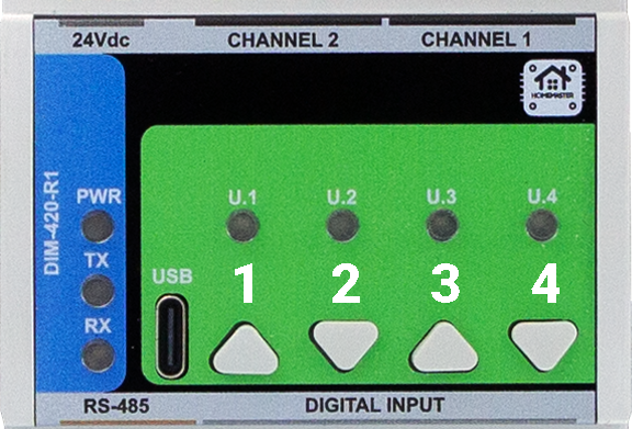
Button Mapping (Front Panel)
| Button | Label | Default Function | Special Use |
|---|---|---|---|
| 1 | U.1 | Action 1 | Hold with U.2 → Enter BOOT/UF2 mode |
| 2 | U.2 | Action 2 | Paired with U.1 |
| 3 | U.3 | Action 3 | Hold with U.4 → Reset to firmware |
| 4 | U.4 | Action 4 | Paired with U.3 |
8.3 Arduino / PlatformIO Notes
🔌 Required Libraries
#include
#include
#include
#include
#include
#include
#include
#include "pico/time.h" // time_us_64(), add_alarm_in_us(), alarm_id_t
9. Maintenance & Troubleshooting
🟢 LED Status
| LED | Meaning |
|---|---|
| PWR | Steady = Power OK |
| TX | Blinks = Sending Modbus |
| RX | Blinks = Receiving Modbus |
| U.1–U.4 | Firmware-controlled |
🧰 Common Issues
| Symptom | Fix / Tip |
|---|---|
| No RS‑485 Comms | Check A/B polarity, Slave ID, baud |
| LED not working | Confirm LED source and mode in WebConfig |
| DI not detected | Use correct GND pair and debounce logic |
| No USB detection | Close all serial monitors; |
| CH not dimming | Check ZC presence, Cut Mode, Lower/Upper |
10. Open Source & Licensing
- Hardware: CERN-OHL-W v2.0
- Firmware: GNU GPLv3
All repositories are publicly available at:
🔗 https://github.com/isystemsautomation/HOMEMASTER/tree/main/DIM-420-R1
11. Downloads
| Item | Link |
|---|---|
| Firmware Source | /Firmware/default_DIM_420_R1 |
| ESPHome Config | default_dim_420_r1_plc.yaml |
| WebConfig Tool | Online Version |
| Schematics (PDF) | /Schematics |
| Mechanical Images | See /Images/ in repo |
| Datasheet | DIM-420-R1.pdf |
12. Support
Need help using, wiring, or flashing the DIM‑420‑R1? Try these:
- 💼 Official Support Portal
- 🔧 WebConfig Tool
- 🎥 YouTube Tutorials
- 💬 Reddit Community
- 🧪 Hackster Projects
Or open an issue on GitHub if you're a developer or tester.