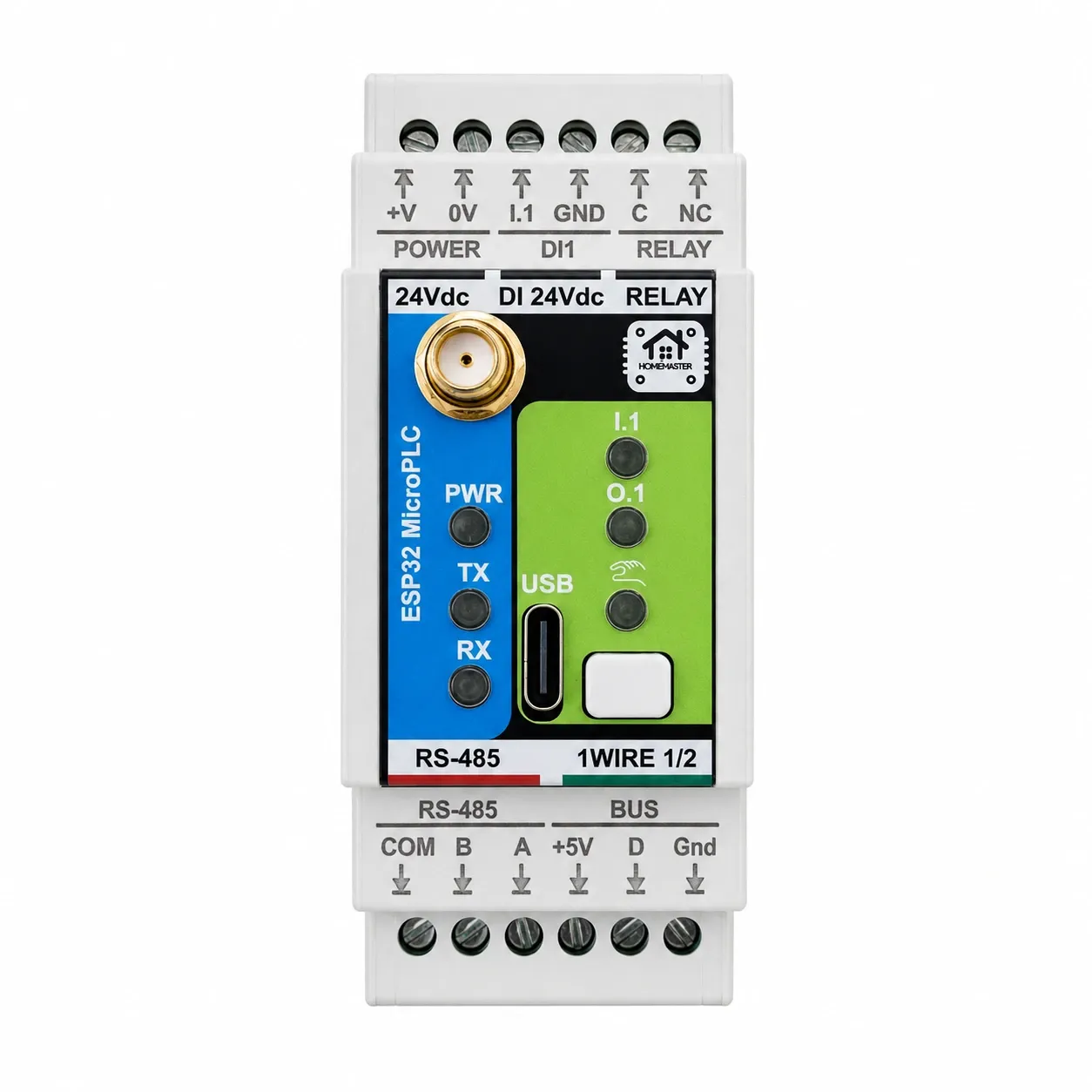
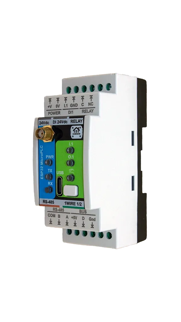
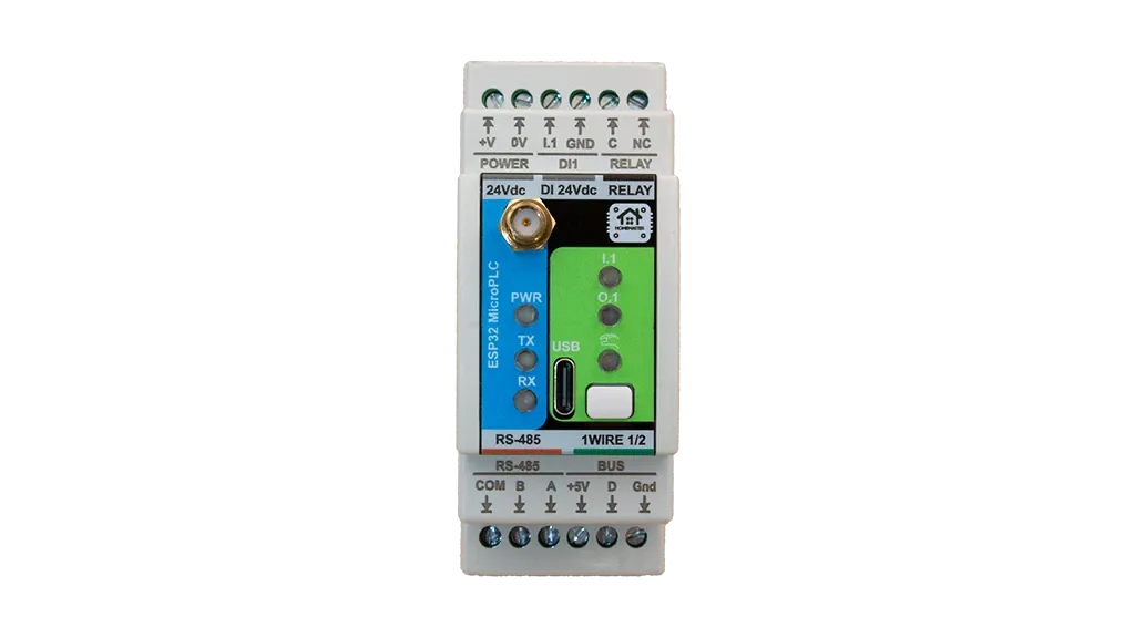
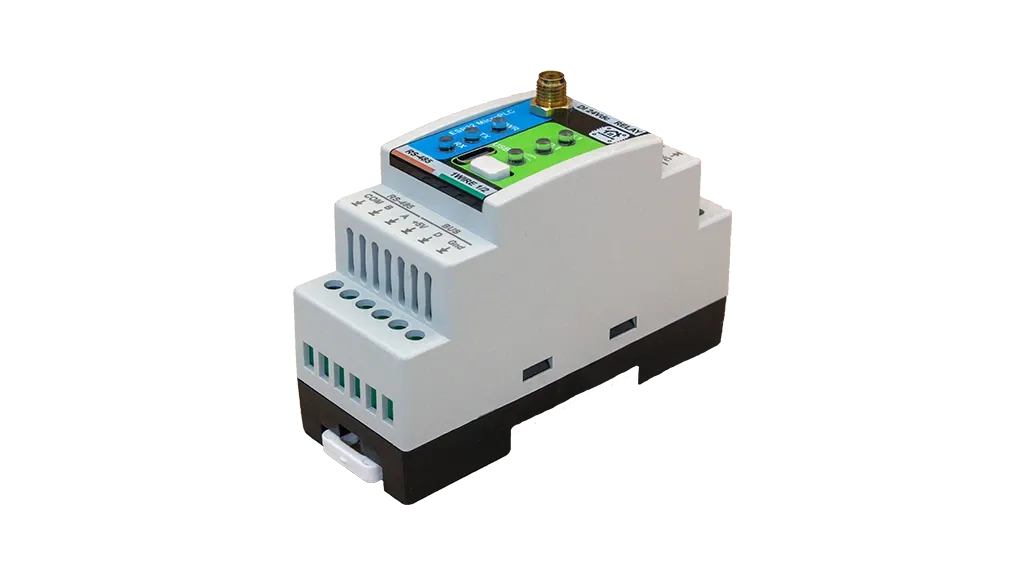
HomeMaster MicroPLC (ESP32)
The HomeMaster MicroPLC is a professional, open-source DIN rail controller built around the ESP32 platform, designed for robust and scalable smart automation in residential, commercial, and light industrial environments. It combines digital inputs, relay outputs, RS-485 communication, real-time clock functionality, and USB programming interface. On a hydronic bus it acts as the Modbus RTU master at the head of a heating installation built from HomeMaster expansion modules.
Integrates with Home Assistant over the native ESPHome API — no MQTT broker, no Modbus register mapping and no custom converters. The device appears in Home Assistant within seconds as ready-to-use entities, with low latency and no cloud.
Engineered for reliability and flexibility, the MicroPLC supports 24 V DC power input and features an integrated RS-485 Modbus interface for expansion with compatible I/O modules and field devices. Its local processing capability ensures continued operation even when network or cloud connectivity is lost, making it suitable for mission-critical applications.
Quick Overview
- ESP32 industrial controller platform
- Industrial DIN-rail form factor with 24 V DC supply
- Runs locally and offline without cloud dependency
- Expandable via RS-485 Modbus field devices
Typical Applications
- Industrial automation controller
- HVAC automation and plant control
- Energy management systems
- Industrial I/O controller
- Building management systems (BMS)
- RS-485 Modbus master / field gateway
- Bus master for a multi-module heating system
Tech Specs
| Specification | Details |
|---|---|
| Microcontroller | ESP32-WROOM-32U-N16 (dual-core) |
| Flash Memory | 16 MB SPI flash |
| SRAM | 536 KB SRAM |
| Power Input | 24 V DC nominal (24VDC) |
| Digital Inputs | 1 × IEC 61131-2 compliant 24 V digital input (ISO1212 front-end), dry-contact (module-wetted), with PTC fuse, TVS surge and reverse-polarity protection |
| Relay Outputs | 1 × relay (HF115F-005-1ZS3), C and NC only (no NO) — functionally SPST-NC; closed when de-energised |
| Temperature Inputs | 1-Wire interface supported |
| User Interface | 1 button, status LEDs |
| Wi-Fi | Integrated Wi-Fi (ESP32) |
| Wi-Fi standard | IEEE 802.11 b/g/n (2.4 GHz) |
| RS-485 | RS-485 Modbus RTU (MAX485, half-duplex), non-isolated; TVS surge protection, PTC fuses, common-mode choke, fail-safe biasing |
| Storage | Internal ESP32 flash |
| USB | USB-C programming interface via CP2102N USB-UART bridge |
| RTC | PCF8563 RTC with CR2032 battery backup |
Installation, Environmental & Mechanical
| Category | Specification | Details |
|---|---|---|
| Terminal Specifications | Terminal type | Pluggable screw terminal blocks, 5.08 mm pitch |
| Terminal pitch | 5.08 mm | |
| Wire cross-section | 0.2–2.5 mm² (AWG 24–12) | |
| Conductor type | Solid or stranded copper | |
| Stranded wire | Ferrules recommended | |
| Tightening torque | 0.4 Nm (max) | |
| Environmental Ratings | Operating temperature | 0 °C to +40 °C |
| Storage temperature | -10 °C to 55 °C | |
| Relative humidity | 0–90 % RH, non-condensing | |
| Ingress protection | IP20 (inside cabinet) | |
| Installation | Indoor control cabinet only; not for outdoor or exposed installation | |
| Terminal protection | All wiring terminals must be protected against accidental contact | |
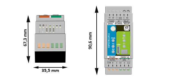
| Mechanical & Packaging | Product dimensions | 35.5 × 91 × 67.3 mm (L × W × H) |
| DIN width | 2 modules (2 × 17.5 mm) | |
| Mounting | 35 mm DIN rail | |
| Net weight | xxx g | |
| Gross weight | xxx g | |
| Pack size | xxx × xxx × xxx mm (L × W × H) | |
| Mechanical drawing | Front + side views with DIN-clip depth (see below) | |
| Notes | All dimensions shown in millimeters unless stated otherwise |
Install only inside a control cabinet with ventilation; the cabinet must include a protective front plate covering all module connection terminals and a closing protective door; not for outdoor or exposed installation.
All wiring terminals must be protected against accidental contact by an insulating front plate, wiring duct, or terminal cover. Exposed live terminals are not permitted.
Home Assistant & ESPHome Integration
The MicroPLC comes with ESPHome pre-installed and can be integrated directly into Home Assistant without flashing custom firmware.
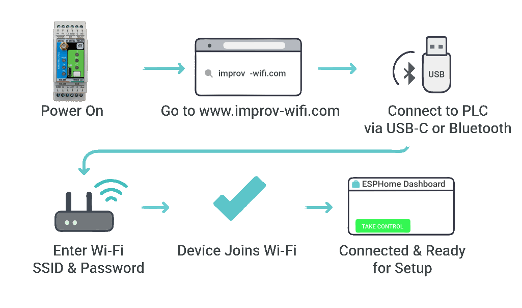
Quick Setup Process (Improv Wi-Fi)
- Mount & Power – Install on a 35mm DIN rail and connect power.
- Open Improv – Go to improv-wifi.com.
- Connect – Use USB-C (Serial) or Bluetooth LE.
- Enter Wi-Fi – Input SSID and password, then press Connect.
- Auto-Discovery – Device appears in Home Assistant & ESPHome Dashboard.
One-Click Import (ESPHome Dashboard)
Once connected to Wi-Fi, the MicroPLC is automatically discovered in ESPHome Device Builder. Within 15 minutes of power-on, click Take control to import the official configuration and establish the per-device API encryption key (firmware 1.1.0). Home Assistant prompts for the key and installs it. Save the key for moves between Home Assistant instances. Power-cycle to reopen the provisioning window if it has closed. USB Serial Improv remains available regardless.
USB Type-C Manual Flashing (Optional)
- Connect the MicroPLC to your computer using USB Type-C.
- Download the official YAML configuration: microplc.yaml
- Open ESPHome Dashboard and import the YAML file.
- Update Wi-Fi credentials in the YAML.
- Flash directly from ESPHome (no reset or boot buttons required).
- The device reboots automatically and runs the new firmware.
- No firmware flashing required for basic use
- Native Home Assistant API
- OTA updates supported
- Automatic ESPHome dashboard import
- Full YAML customization
Extension modules sit on the same RS-485 bus and are configured against this controller. The MiniPLC is the larger sibling — same ESP32 and the same firmware, different onboard I/O, mains input and Ethernet. To work out how many modules a panel needs and how wide it comes out, use the System Builder.
The RS-485 bus accepts any combination of expansion modules and field hardware: actuators, pumps, sensors and the boiler interface are specified per circuit, independent of the controller on the DIN rail.
New to this kind of system? Two guides cover the ground: building a Home Assistant automation system and a wired ESPHome smart home. A full build using this controller is written up in the MicroPLC chimney automation guide.
Going deeper on this module: wiring a new house before the walls close, what still works when Home Assistant is down and RS-485 and Modbus wiring, termination and timeouts. Related modules: STR-3221-R1, AIO-422-R1, DIO-430-R1 and the OpenTherm Gateway.
Documentation
The MicroPLC is open-source hardware. You can build your own board using the files below.
Hardware Design Files
| File | Description | Link |
|---|---|---|
| Schematic (MCU Board) | Main controller board schematic | MCUBoard.pdf |
| Schematic (Relay Board) | Relay and power section schematic | RelayBoard.pdf |
Compliance Documents
| File | Description | Link |
|---|---|---|
| EU Declaration of Conformity (DoC) | Signed EU Declaration of Conformity per Reg. (EC) 765/2008 and Decision 768/2008/EC | DoC_MicroPLC.pdf |
| Datasheet | Technical specifications and electrical characteristics | MicroPLC_Datasheet.pdf |
Firmware & Software
| Resource | Description | Link |
|---|---|---|
| Default ESPHome Config | Pre-configured YAML for Home Assistant | microplc.yaml |
| Firmware Source Code | Latest firmware builds and source | Firmware/ |
| ESPHome Integration Guide | Complete setup instructions | README.md |
Power Supply
The MicroPLC is powered by 24 V DC nominal on V+ / 0V terminals.
Power Input Specifications
| Input Option | Terminals | Range | Notes |
|---|---|---|---|
| 24 V DC | V+ / 0V | 24 V DC | Powers internal rail +24VDC_FUSED. |
24 V DC Input (V+ / 0V)
- Typical operating current: 150 mA @ 24 V (≈ 3.6 W) — measured typical device power consumption
- Internal rail: 24 V input is conditioned into +24VDC_FUSED
- Input protection: surge suppression (TVS), EMI filtering, reverse-polarity / power-path protection
- Internal protection: 1.0 A soldered service fuse and resettable PTC protection devices
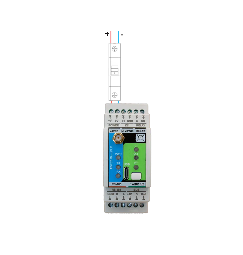
- Upstream protection (recommended): external 0.5 A slow-blow fuse or 0.5 A breaker on V+ so the external device clears before the internal service fuse. Recommended to protect wiring and simplify troubleshooting.
- Use a regulated 24 V DC supply
- Install 0.5 A fuse/breaker upstream of V+
- Observe polarity: V+ / 0V
- Route power wiring away from low-level analog signal wiring
Inputs & Outputs
Digital Inputs (1 channel)
| Channel | Pin | Type | Voltage | Description |
|---|---|---|---|---|
| DI #1 | DI24V (ESP32 GPIO via ISO1212) | Dry contact (module-wetted) | 24 V DC | Isolated 24 V digital input with internal field supply, dry contact |
Features:
- 1× IEC 61131-2 compliant 24 V DC digital input (ISO1212 front-end), dry-contact (module-wetted), with PTC fuse, TVS surge and reverse-polarity protection
- Internal fused 24 V field supply for dry-contact sensing
- Module-wetted inputs for potential-free contacts (relay contacts, open-collector / transistor outputs)
- Separate field ground and logic ground domains
- Per-channel protection with resettable PTC fuses and TVS surge suppression
- Integrated EMI and noise filtering on each input
- Configurable input inversion and debounce filtering via ESPHome
- Status monitoring via Home Assistant binary sensors
Connect potential-free (dry) contacts — wall switches, push buttons, or relay / open-collector / transistor outputs that simply close the input to its GND return. The module supplies the wetting current from its own 24 V rail; do not feed external voltage into the input. Three-wire sensors must be powered from your own supply, with their switching output wired to the input (the module provides no sensor-supply rail).
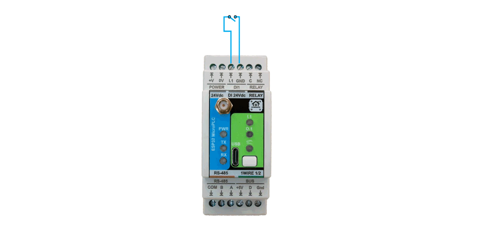
⚠️ NC relay (reserve): The relay output is dry-contact and exposes only C and NC (no NO). When the device is unpowered or the relay is switched OFF, the NC contact is closed and the load is energized. This channel is a reserve for the installer — use it where equipment must switch on if the panel loses power. For failsafe-off loads (pumps, valves, heaters), use a module with NO/SPDT contacts (e.g. DIO-430-R1).
Relay Outputs
The MicroPLC provides 1 mechanical relay (HF115F-005-1ZS3) for switching AC or DC loads. Only C and NC terminals are exposed (no NO) — functionally SPST-NC. The contact is closed when de-energised. Driven via optocoupler-isolated control circuitry.
System/board rating: 3 A MAX per output (system limit). The MicroPLC board/system can safely carry ONLY 3 A per relay output. This limit is determined by PCB trace width, terminal block rating, and thermal constraints, not the relay component rating. Using more than 3 A directly can overheat and permanently damage the board.
Relay contact (component) rating: 16 A @ 250 V AC (resistive). This value belongs ONLY to the relay component itself and is NOT usable as a system output rating. The MicroPLC must NOT be used above 3 A.
Loads above 3 A (or inductive/inrush loads) MUST be switched using an external contactor or power relay. The MicroPLC relay may be used as a control signal for the external contactor. Do not attempt to switch loads above 3 A directly through the MicroPLC relay outputs.
⚠️ External protection required: Every relay output MUST be protected by an external fuse or circuit breaker (max 3 A per channel). Relay output circuits are not internally fused. External overcurrent protection is mandatory for safe operation.
Relay Specifications
| Channel | Control Pin | Type | Rating | Description |
|---|---|---|---|---|
| Relay #1 | RELAY (ESP32 GPIO via optocoupler driver) | SPST-NC (C/NC only) | 16A @ 250V AC (relay component rating, NOT usable as system output) 3 A MAX per output (board/system limit) |
General purpose relay output 1 (C/NC only; closed when de-energised) |
Relay Wiring Examples
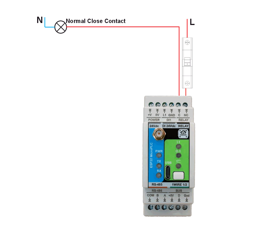
- Relay exposes C / NC only — there is no NO terminal
- There is no NO terminal — use DIO-430-R1 for failsafe-off loads
- NC is closed when de-energised — load is powered by default; do not use for failsafe-off loads
- ⚡ Loads may carry hazardous voltage
- Supports AC and DC switching (DC and inductive loads require derating)
⚠️ External protection rule: Every relay output MUST be protected by an external fuse or circuit breaker. The rated current of the protective device shall not exceed 3 A MAX per output (board/system limit).
⚠️ Common protection warning: If a single common fuse or circuit breaker is used to protect multiple relay outputs (as shown in the wiring example), the protective device shall NOT be sized by summing relay outputs. The rating of the common protective device shall not exceed 3 A MAX per output (board/system limit).
For inductive or DC loads (contactors, solenoids, motors), use appropriate suppression (RC snubbers, MOVs, or flyback diodes). Loads exceeding the recommended PCB current limit shall be switched using external contactors or wiring methods that bypass PCB copper paths.
Temperature Inputs
MicroPLC supports 1-Wire temperature sensors (DS18B20 or compatible) for reliable cabinet and process temperature monitoring.
Temperature Input Specifications
| Type | Channel | Sensor / Interface | Range | Accuracy |
|---|---|---|---|---|
| 1-Wire | BUS #1 | 1-WIRE | -55°C to +125°C | ±0.5°C |
Wiring Examples
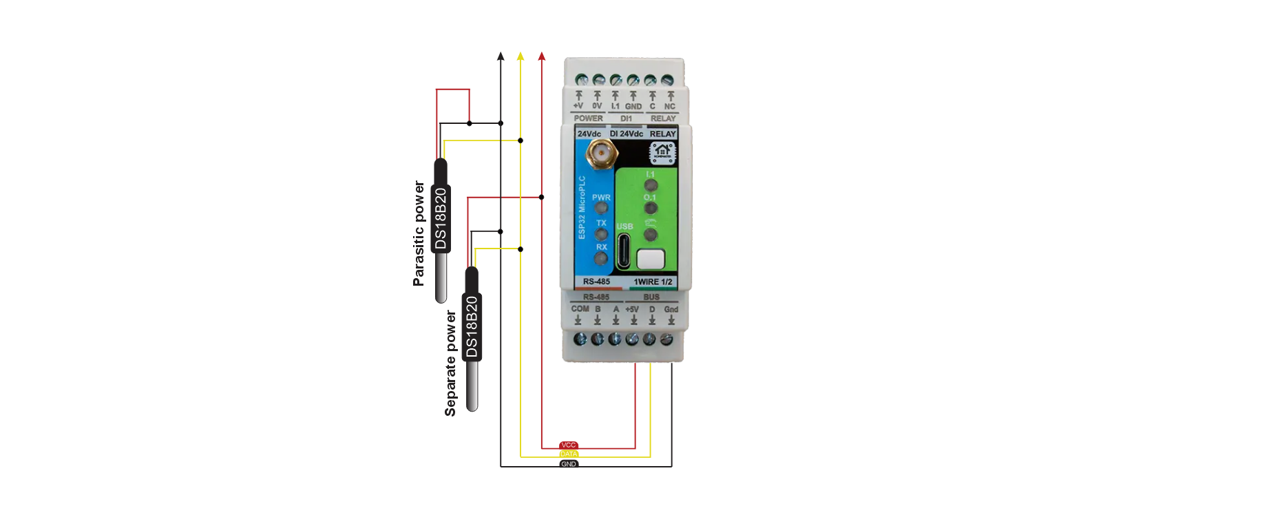
Limitations / Notes
- Recommended topology: daisy-chain configuration (see wiring example above)
- Maximum number of sensors (recommended): ≤ 10 sensors per bus
- Typical maximum cable length (recommended): ≤ 50 m using shielded cable with proper topology
- Power mode: External power using +5V/GND is recommended. Parasitic power mode is not recommended for long cable runs or multiple sensors.
User Interface
| Component | Quantity | Control | Description |
|---|---|---|---|
| Button | 1 | BUTTON | User button for local control |
| LED1 | 1 | +5V rail | +5V power indicator |
| LED2 | 1 | RLED | Relay status LED (hardware-driven) |
| LED3 | 1 | LED | Firmware-configurable status LED |
| LED4 | 1 | DI | Digital input status indicator |
| LED5 | 1 | RS-485 RX | RS-485 receive activity indicator |
| LED6 | 1 | RS-485 TX | RS-485 transmit activity indicator |
Features:
- 1× user button for local control (BUTTON)
- LED1 indicates internal +5V power
- LED3 is a firmware-configurable status LED
- LED4 indicates digital input state (DI)
- LED5/LED6 indicate RS-485 RX/TX activity
Communication & Protocols
- Modbus RTU (RS-485) – UART-based communication for expansion modules and field devices
- Wi-Fi – ESP32 integrated (Improv onboarding supported)
RS-485 / Modbus RTU
Terminal order differs across the HomeMaster range. Always read the silkscreen - do not wire by habit from another module. On this module the order is COM-B-A. Swapping A and B damages nothing but the node will not communicate. COM is required on every node.
All HomeMaster controllers and modules share the same RS-485 front end.
| Item | Value |
|---|---|
| Transceiver | MAX485CSA+T, half-duplex |
| Galvanic isolation | None — the transceiver shares the device's logic ground |
| Common-mode range | −7 V … +12 V referred to the device's own ground (MAX485 limit) |
| Terminals | A / B / COM |
| Surge protection | 3 × SMAJ6.8CA TVS (A–COM, B–COM, A–B) |
| Overcurrent | 2 × resettable PTC, 1.5 A hold, in series with A and B |
| EMI filtering | Common-mode choke on the A/B pair; COM referenced through 1 MΩ ∥ 4.7 nF |
| Idle state | Fail-safe biasing on board — do not add external bias resistors |
| Termination | 120 Ω at the two physical ends of the bus only |
Bus wiring rules — apply to every device on the bus:
- One twisted pair for A/B, 120 Ω characteristic impedance.
- Run COM to every node. Required, not optional: the ports are not isolated, and COM is what bounds the common-mode voltage the transceivers see.
- Prefer one power supply for the whole bus, distributed in star topology. With separate supplies, additionally tie the 0 V references together at a single point.
- Bond the cable shield to cabinet PE at one end only. Never land a shield on A, B or COM.
- Where the bus crosses into a different electrical installation with its own earthing reference — a utility or billing meter, another building, another cabinet's PE system — fit an external galvanic RS-485 isolator at that boundary. The on-board components are transient protection, not isolation, and will not survive a sustained ground-potential difference.
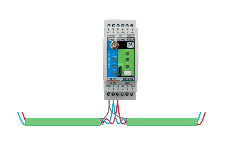
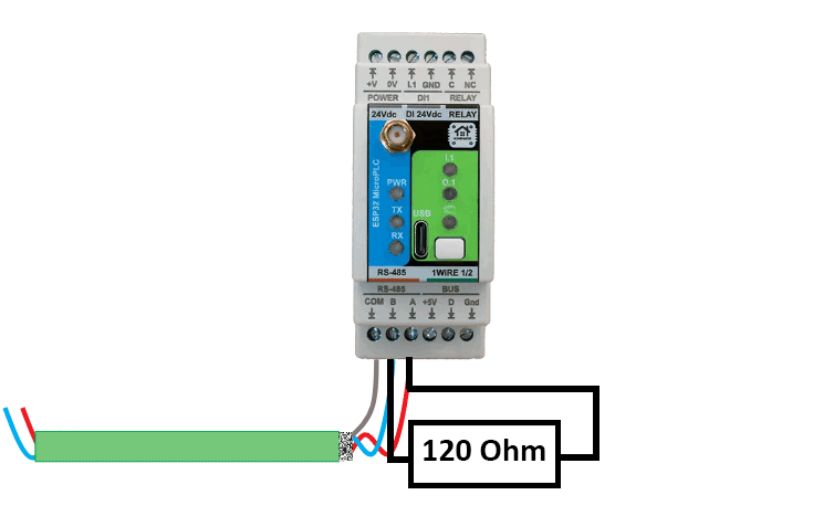
Tip: Cable recommendations, shield bonding, and routing rules are defined in the Cable Recommendations & Shield Grounding section below.
Cable Recommendations & Shield Grounding
This section applies to Analog (0–10V), Temperature (RTD / 1-Wire), and RS-485. Use shielded, twisted constructions and bond shields correctly to reduce EMI and ground-loop issues.
General Routing Rules
- Route low-level signal cables (Analog/RTD/1-Wire/RS-485) separately from mains, relay outputs, contactors, VFD motor cables, and power wiring.
- If crossing power cables is unavoidable, cross at 90°.
- Keep cable runs as short as practical and avoid parallel runs with high-current conductors.
1-Wire (DS18B20)
- Recommended: shielded 3-core ( +5V / DATA / GND ) for typical installations
- High-EMI / long runs: shielded pairs + overall shield (e.g. LI2YCY PIMF 2×2×0.50)
- Topology: daisy-chain (bus). Avoid star wiring.
- Stubs: keep sensor stubs ≤ 0.5 m.
- Pull-up (DATA): 4.7 kΩ typical; 2.2–3.3 kΩ for long/heavy loads.
RS-485 Cable
- Construction: twisted pair for A/B
- Characteristic impedance: 120 Ω (recommended)
- Shielding: overall shield is recommended in cabinets; use individually shielded pairs + overall shield in high-EMI
- Examples: J-Y(ST)Y 2×2×0.5 mm² or LI2YCY PiMF 2×2×0.50
- Use one twisted pair for A/B and a third conductor for COM. COM must be run to every node.
Shield Grounding
- Default recommendation: bond cable shield(s) to cabinet PE/EMC ground at the PLC end only.
- Do not connect shields to signal terminals (AI/AO/RTD/1-Wire/RS-485 A/B/COM).
- If both ends are in equipotential bonded cabinets, shields may be bonded at both ends using proper 360° clamps.
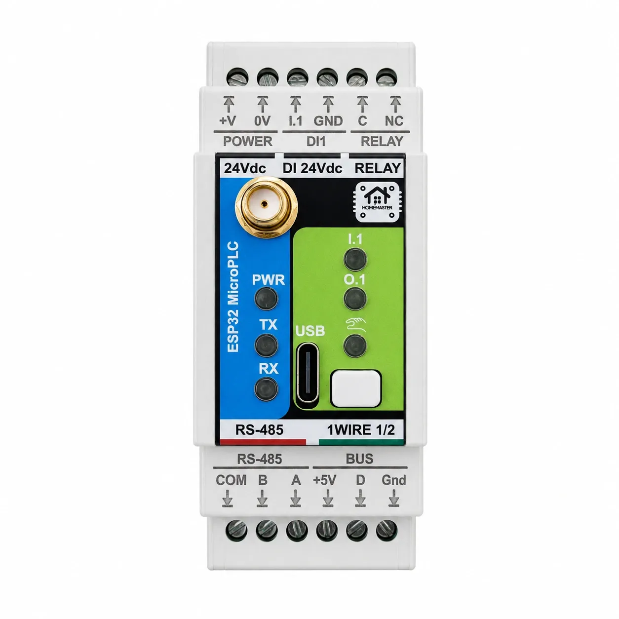
Connectors & terminal map
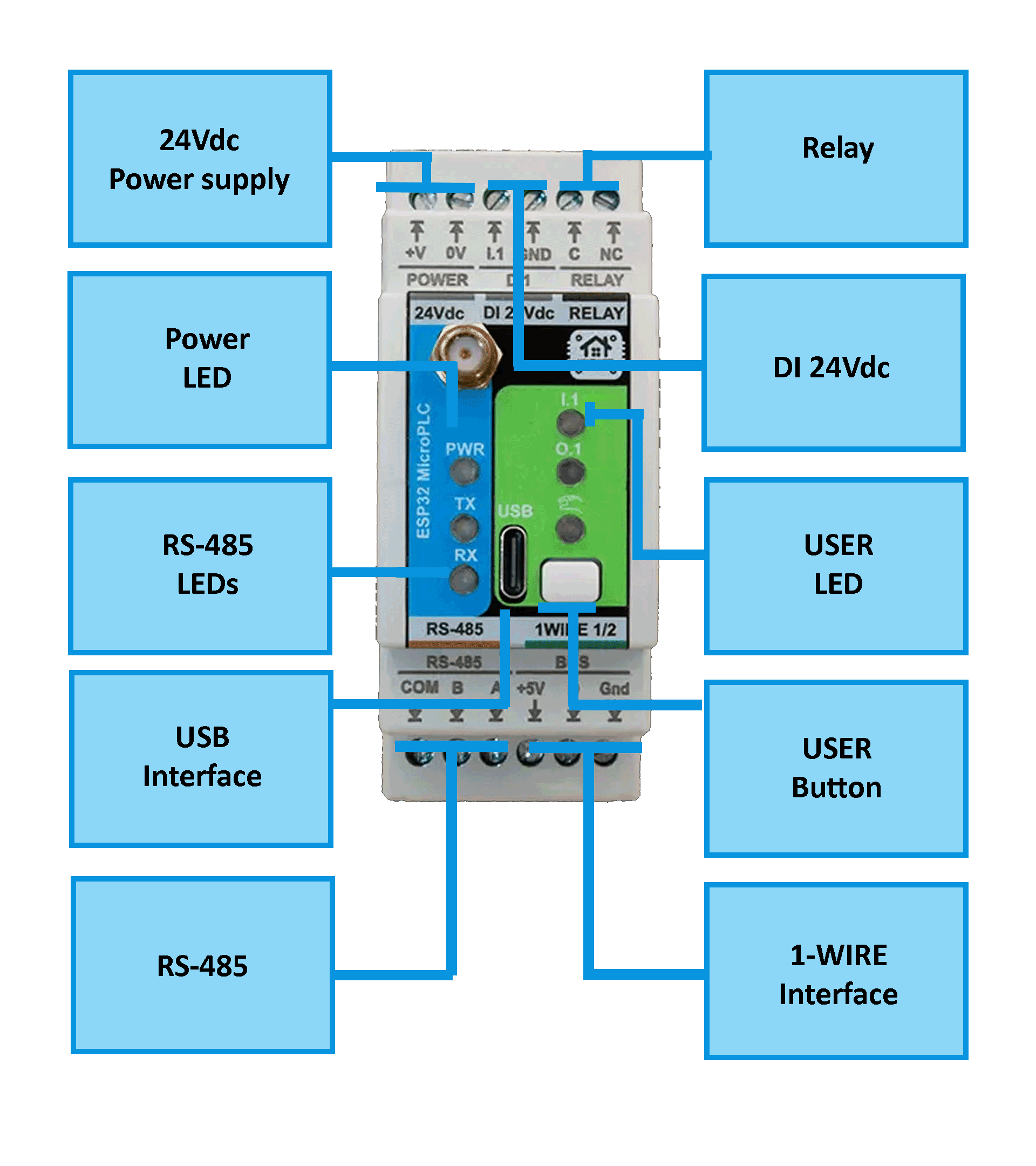
Top row (24Vdc | DI 24Vdc | RELAY)
| Pos | Label | Group | Function |
|---|---|---|---|
| 1 | +V | POWER | 24 V DC input |
| 2 | 0V | POWER | 24 V DC return |
| 3 | I.1 | DI1 | DI1 input |
| 4 | GND | DI1 | DI1 return |
| 5 | C | RELAY | Relay common |
| 6 | NC | RELAY | Relay normally closed |
Bottom row (RS-485 | BUS)
| Pos | Label | Group | Function |
|---|---|---|---|
| 1 | COM | RS485 | RS-485 signal reference |
| 2 | B | RS485 | RS-485 data - |
| 3 | A | RS485 | RS-485 data + |
| 4 | +5V | BUS | 1-Wire sensor supply |
| 5 | D | BUS | 1-Wire data |
| 6 | Gnd | BUS | 1-Wire ground |
Ports & service interfaces
| Id | Type | Note |
|---|---|---|
| USB-C | 5 V via USB-C (programming) |
Housing notes
- Relay exposes C and NC only. There is no NO terminal and the contact is CLOSED when the relay is de-energised - the same inverted behaviour as the OpenTherm Gateway.
- ONE 1-Wire bus. The '1WIRE 1/2' legend labels the two data terminals of a single bus, not two buses.
- DI pair reads signal-then-GND, like DIM and opposite to DIO.
- Power reads +V then 0V.
System Architecture & Pinout
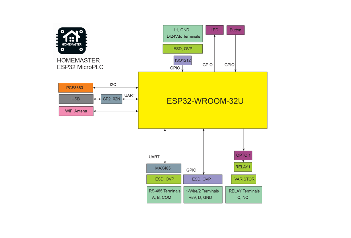
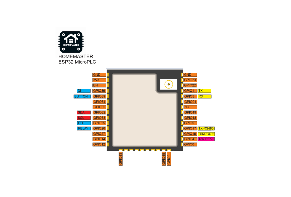
Compliance & Certifications
The MicroPLC module is CE marked. ISYSTEMS AUTOMATION S.R.L. (HomeMaster® brand) maintains the technical documentation and a signed EU Declaration of Conformity (DoC) available for download in the Documents and Resources section above.
- EMC Directive 2014/30/EU — EN 55032:2015 (Class B emissions), EN 55035:2017 (immunity), tested by Idvorsky Laboratories Ltd. (Job #1648)
- Low Voltage Directive 2014/35/EU — EN 62368-1:2020 + A11:2020, in-house dielectric and isolation testing by ISYSTEMS AUTOMATION compliance laboratory
- RoHS Directive 2011/65/EU — EN IEC 63000 technical documentation
- HomeMaster® — registered EU trademark (EUTM No. 019082911, EUIPO, registered 15 January 2025)
Licensing. Hardware design files — schematics, PCB layouts and bills of materials — are published under CERN-OHL-W v2. Firmware and the ESPHome integration packages are published under the MIT licence. Full terms are in the LICENSE files in the HOMEMASTER repository.
Build Guides & Tutorials
Step-by-step projects built with the MicroPLC.
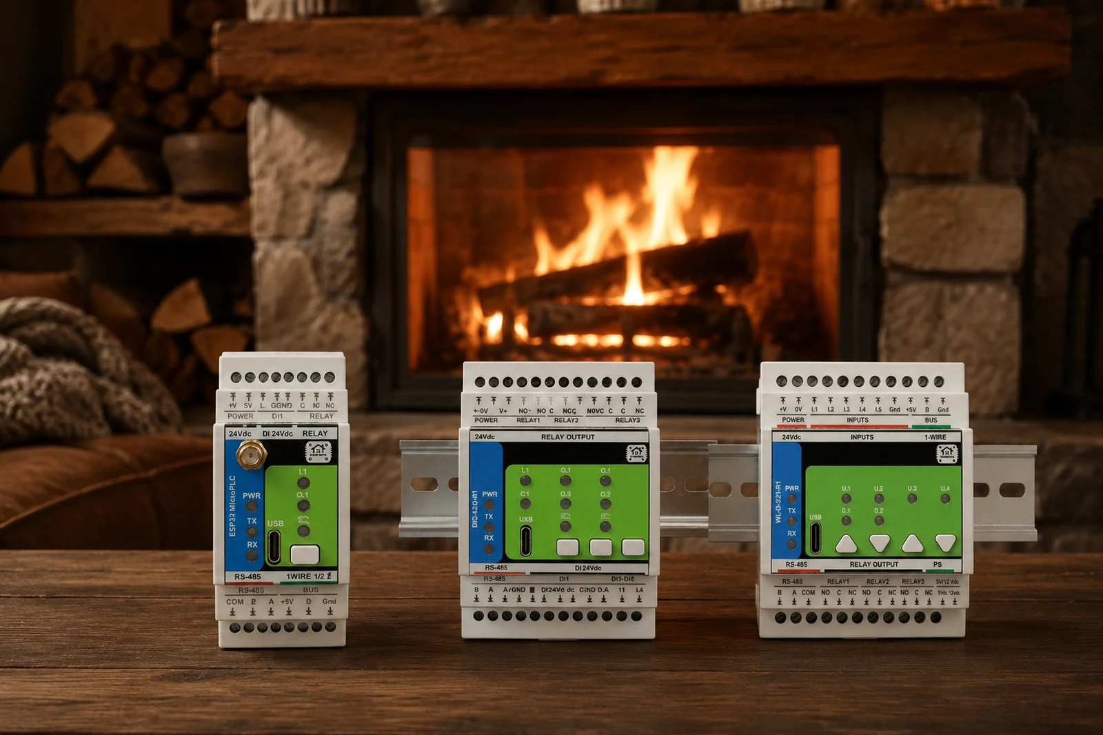
Wood-fired fireplace water-jacket automation: two-pump logic, Modbus heat metering and gas-boiler fallback.
Related products
These other products might interest you