


HomeMaster MiniPLC (ESP32)
The HomeMaster MiniPLC is a professional, open-source DIN rail controller built around the ESP32 platform, designed for robust and scalable smart automation in residential, commercial, and light industrial environments. It combines extensive onboard I/O—including relays, digital and analog inputs, temperature sensors, and a user interface—with native Home Assistant integration via pre-installed ESPHome.
Engineered for reliability and flexibility, the MiniPLC supports multiple power input options (24V DC or wide-range AC/DC) and features RS-485 Modbus interface for expansion with a wide range of compatible I/O modules. Its local processing capability ensures continued operation even when network or cloud connectivity is lost, making it suitable for mission-critical applications.
This controller operates as a complete standalone automation system using its comprehensive onboard I/O, while also offering seamless expansion via the RS-485 bus to connect HomeMaster smart modules for energy metering, lighting control, security, and more. It provides a versatile, ready-to-integrate platform for HVAC control, energy management, security systems, lighting automation, and custom industrial applications.

Quick Overview
- Pre-installed ESPHome for native Home Assistant integration
- Industrial DIN-rail form factor with 24 V DC supply
- Runs locally and offline without cloud or HA
- Expandable via RS-485 Modbus field devices
Typical Applications
- Smart home central controller
- HVAC automation and plant control
- Solar and energy management systems
- Laboratory automation
- Industrial I/O gateway
- Building management systems (BMS)
- SCADA edge controller
- RS-485 Modbus master / field gateway
Tech Specs
| Specification | Details |
|---|---|
| Microcontroller | ESP32-WROOM-32U (dual-core) |
| Power Input | 24 V DC nominal (V+ / 0V) OR 85–265 V AC (L / N) OR 120–370 V DC (L / N + / −) |
| Digital Inputs | 4 × isolated, 24 V DC compatible |
| Relay Outputs |
6 × SPDT — 3 A MAX continuous per output (board/system limit). Relay component contacts rated up to 12 A @ 250 V AC (resistive). |
| Analog Inputs | 4 × 0–10 V, 16-bit (ADS1115) |
| Analog Output | 1 × 0–10 V, 12-bit (MCP4725) |
| Temperature Inputs | 2 × RTD (PT100/PT1000 via MAX31865), 2 × 1-Wire (DS18B20 compatible) |
| Display | 128 × 64 OLED (SH1106) |
| User Interface | 4 buttons, 3 user LEDs, 1 status LED, onboard buzzer (GPIO2, PWM) |
| Wi-Fi | Wi-Fi (ESP32) |
| Ethernet | Optional Ethernet (LAN8720 PHY) |
| RS-485 | RS-485 Modbus RTU (MAX485, half-duplex) with TVS surge protection, PTC fuses, EMI choke, and fail-safe biasing |
| Storage | MicroSD card (SPI interface, power-switched 3.3 V rail) |
| USB | USB-C (ESD protected, CC detection, data to ESP32) |
| RTC | PCF8563 with battery backup |
Note: Relay outputs are not internally fused. Use external overcurrent protection per local code and use an external contactor/relay for loads above 3 A or with high inrush/inductive characteristics.
Installation, Environmental & Mechanical
| Category | Specification | Details |
|---|---|---|
| Terminal Specifications | Terminal type | Pluggable screw terminal blocks, 5.08 mm pitch |
| Terminal pitch | 5.08 mm | |
| Wire cross-section | 0.2–2.5 mm² (AWG 24–12) | |
| Conductor type | Solid or stranded copper | |
| Stranded wire | Ferrules recommended | |
| Tightening torque | 0.4 Nm (max) | |
| Environmental Ratings | Operating temperature | 0 °C to +40 °C |
| Storage temperature | -10 °C to 55 °C | |
| Relative humidity | 0–90 % RH, non-condensing | |
| Ingress protection | IP20 (inside cabinet) | |
| Installation | Indoor control cabinet only; not for outdoor or exposed installation | |
| Terminal protection | All wiring terminals must be protected against accidental contact | |
| Mechanical & Packaging | Product dimensions | 157.4 × 91 × 58.4 mm (6.2 × 3.58 × 2.3 in) (L × W × H) |
| DIN units | 9 division units (≈ 90 mm DIN rail mounting width) | |
| Mounting | 35 mm DIN rail | |
| Net weight | 300 g | |
| Gross weight | 450 g | |
| Pack size | 230 × 140 × 87 mm (9 × 5.5 × 3.4 in) (L × W × H) | |
| Mechanical drawing | Front + side views with DIN-clip depth (see below) | |
| Notes | All dimensions shown in millimeters unless stated otherwise |
Install only inside a control cabinet with ventilation; the cabinet must include a protective front plate covering all module connection terminals and a closing protective door; not for outdoor or exposed installation.
All wiring terminals must be protected against accidental contact by an insulating front plate, wiring duct, or terminal cover. Exposed live terminals are not permitted.

Home Assistant & ESPHome Integration
The MiniPLC comes with ESPHome pre-installed and can be integrated directly into Home Assistant without flashing custom firmware.
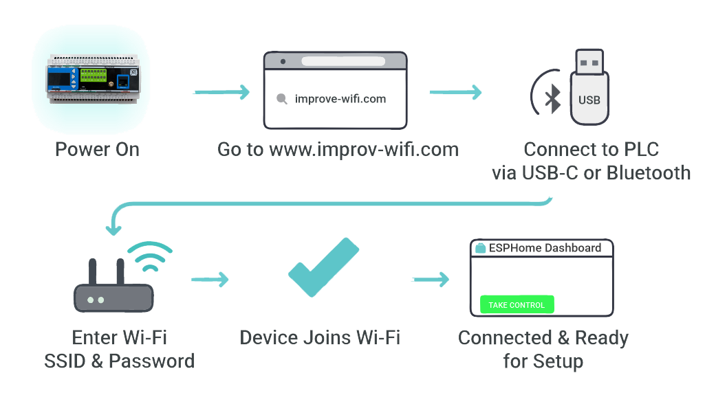
Quick Setup Process (Improv Wi-Fi)
- Mount & Power – Install on a 35mm DIN rail and connect power.
- Open Improv – Go to improv-wifi.com.
- Connect – Use USB-C (Serial) or Bluetooth LE.
- Enter Wi-Fi – Input SSID and password, then press Connect.
- Auto-Discovery – Device appears in Home Assistant & ESPHome Dashboard.
One-Click Import (ESPHome Dashboard)
Once connected to Wi-Fi, the MiniPLC is automatically discovered in the ESPHome Dashboard. Click “Take Control” to import the official configuration directly from GitHub.
USB Type-C Manual Flashing (Optional)
- Connect the MiniPLC to your computer using USB Type-C.
- Download the official YAML configuration: miniplc.yaml
- Open ESPHome Dashboard and import the YAML file.
- Update Wi-Fi credentials in the YAML.
- Flash directly from ESPHome (no reset or boot buttons required).
- The device reboots automatically and runs the new firmware.
- No firmware flashing required for basic use
- Native Home Assistant API
- OTA updates supported
- Automatic ESPHome dashboard import
- Full YAML customization
Documentation
The MiniPLC is open-source hardware. You can build your own board using the files below.
Hardware Design Files
| File | Description | Link |
|---|---|---|
| Schematic (MCU Board) | Main controller board schematic | MCU_Board.pdf |
| Schematic (Relay Board) | Relay and power section schematic | Relay_Board.pdf |
| Schematic (USB Board) | USB-C interface and power management | USB_Board.pdf |
Firmware & Software
| Resource | Description | Link |
|---|---|---|
| Default ESPHome Config | Pre-configured YAML for Home Assistant | miniplc.yaml |
| Firmware Source Code | Latest firmware builds and source | Firmware/ |
| ESPHome Integration Guide | Complete setup instructions | README.md |
Manuals & Datasheets
| Document | Description | Link |
|---|---|---|
| Datasheet | Technical specifications and ratings | Datasheet.pdf |
| User Manual | Installation and configuration guide | User_Manual.pdf |
Power Supply
⚠️ Critical: Exactly ONE power input method may be used at a time. V+ / 0V and L / N must never be connected simultaneously.
MiniPLC supports one power input method at a time: 24 V DC nominal on V+ / 0V (recommended) or Mains AC / High-Voltage DC on L / N via the onboard isolated power module.
When to use which: 24 V DC is recommended when available, as it is safer and simpler to install. Mains AC / High-Voltage DC on L / N is for installations where 24 V DC is not available and must be installed by qualified personnel in accordance with local electrical codes.
⚠️ Safety reminder: When using L / N terminals for mains AC or high-voltage DC, ensure all power is disconnected before any wiring work. Installation and maintenance must be carried out by qualified personnel in accordance with local electrical codes, including proper overcurrent protection.
Power Input Specifications
| Input Option | Terminals | Range | Notes |
|---|---|---|---|
| 24 V DC (recommended) | V+ / 0V | 24 V DC | Preferred for most installations. Powers internal rail +24VDC_FUSED. |
| Mains AC | L / N | 85–265 V AC, 47–63 Hz | Uses onboard isolated module to generate the internal 24 V rail. External protection required. |
| High-Voltage DC | L / N (+ / −) | 120–370 V DC | Uses onboard isolated module to generate the internal 24 V rail. External protection required. |
24 V DC Input (V+ / 0V)
- Typical operating current: 150 mA @ 24 V (≈ 3.6 W) — measured typical device power consumption
- Internal rail: 24 V input is conditioned into +24VDC_FUSED
- Input protection: surge suppression (TVS), EMI filtering, reverse-polarity / power-path protection
- Internal service fuse: 1.0 A (soldered) — service replacement required if blown
- Upstream protection (recommended): external 0.5 A slow-blow fuse or 0.5 A breaker on V+ so the external device clears before the internal service fuse. Recommended for 24 V DC installations to protect wiring and simplify troubleshooting.
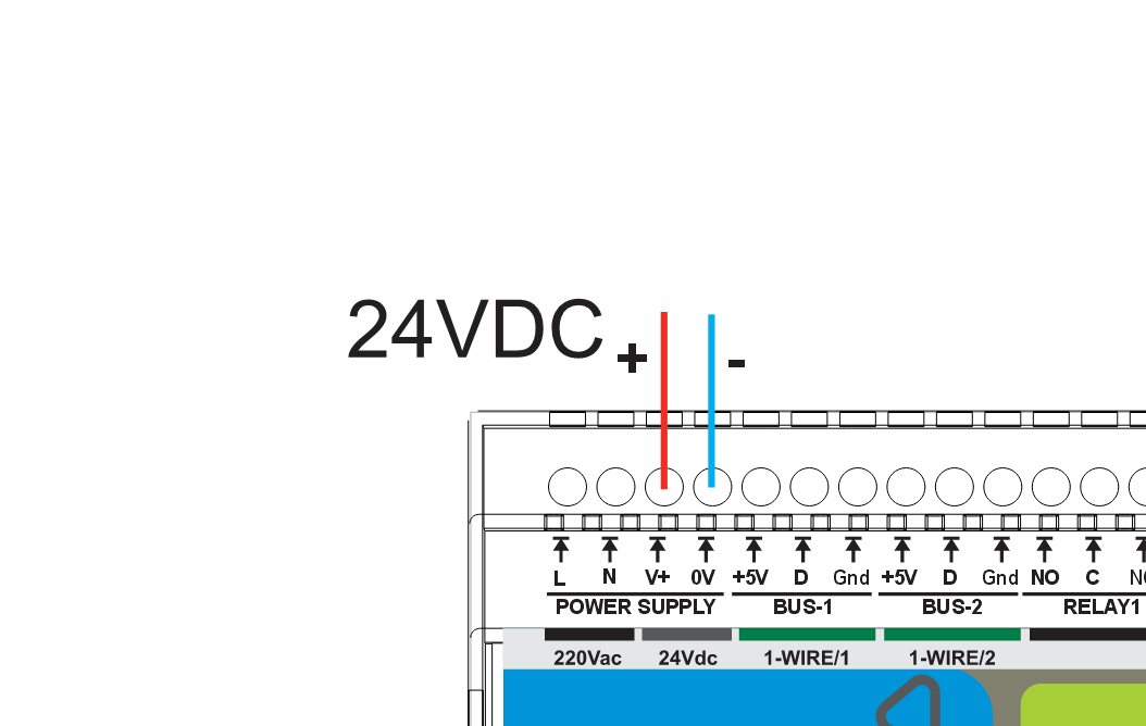
- Use a regulated 24 V DC supply
- Install 0.5 A fuse/breaker upstream of V+
- Observe polarity: V+ / 0V
- Route power wiring away from low-level analog signal wiring
Mains AC / High-Voltage DC Input (L / N)
The onboard isolated power module generates the internal 24 V rail from 85–265 V AC or 120–370 V DC on L / N.
Mandatory upstream protection (L / N): install an external T0.5 A (slow-blow) fuse or 0.5 A breaker upstream. Increase rating only if required by local code or to prevent nuisance trips due to inrush. External protection is required for mains AC / high-voltage DC installations due to safety regulations and the higher fault current available from these sources.
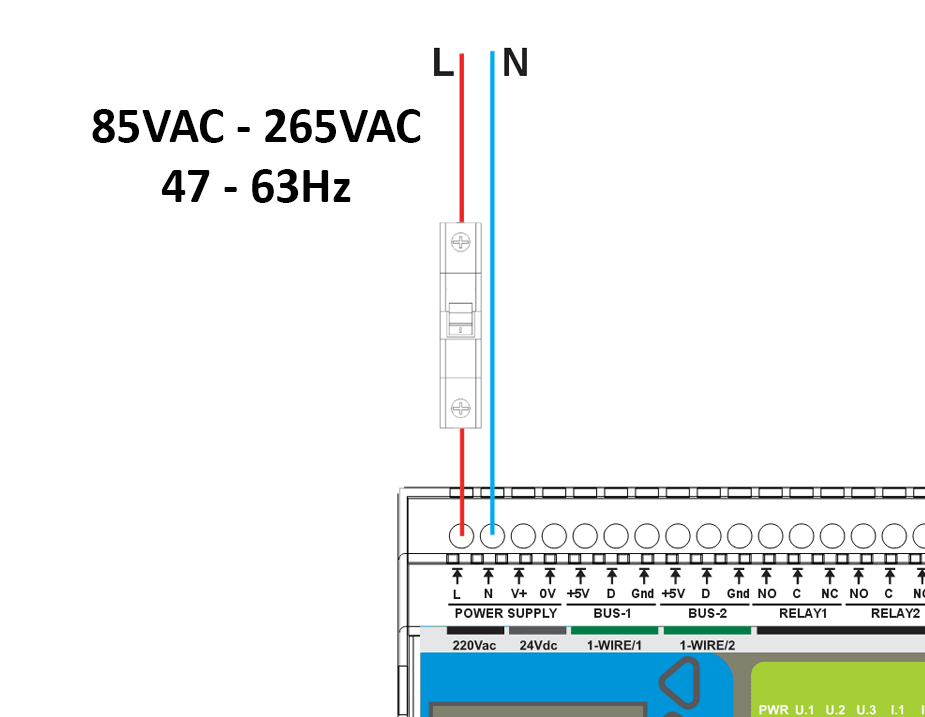
- Input: 85–265 V AC, 47–63 Hz
- Qualified personnel only
- External fuse/breaker required
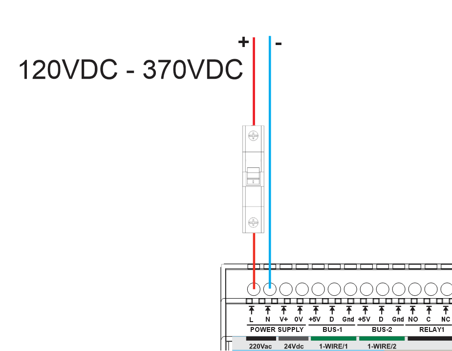
- Input: 120–370 V DC
- Observe polarity where marked on L / N
- External fuse/breaker required
| Onboard Isolated Power Module | |
|---|---|
| Type | Isolated AC/DC power module |
| Input | 85–265 V AC (47–63 Hz) or 120–370 V DC |
| Output | 24 V DC auxiliary rail — maximum capacity 220 mA (power module rating, not typical device draw) |
| Protection | Overcurrent, short-circuit, thermal shutdown with auto-recovery |
Current draw clarification: The 150 mA figure is the typical operating current drawn by the MiniPLC device itself. The 220 mA figure is the maximum output capacity rating of the onboard isolated power module. Current is drawn by the load (the MiniPLC); the higher number represents the module's capacity limit, not additional current consumption.
Important: Use only one input method at a time: V+/0V or L/N.
Inputs & Outputs
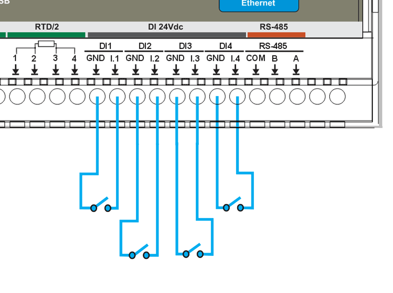
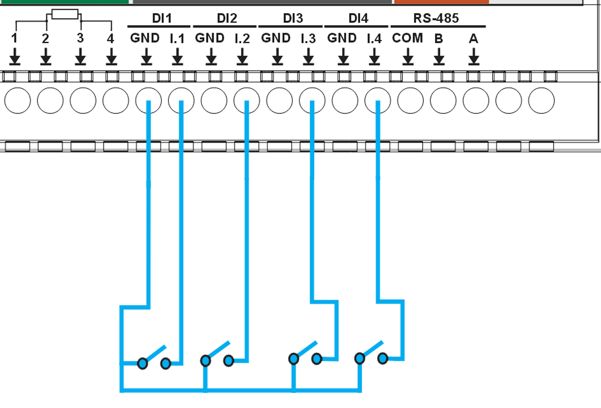
Digital Inputs (4 channels)
| Channel | Pin | Type | Voltage | Description |
|---|---|---|---|---|
| DI #1 | GPIO36 | Sourcing | 24 V DC | Isolated 24 V digital input with internal field supply, dry contact |
| DI #2 | GPIO39 | Sourcing | 24 V DC | Isolated 24 V digital input with internal field supply, dry contact |
| DI #3 | GPIO34 | Sourcing | 24 V DC | Isolated 24 V digital input with internal field supply, dry contact |
| DI #4 | GPIO35 | Sourcing | 24 V DC | Isolated 24 V digital input with internal field supply, dry contact |
Features:
- 4× isolated 24 V DC digital inputs using ISO1212 digital input receivers
- Internal fused 24 V field supply for dry-contact sensing
- Sourcing-type inputs for passive devices (relay contacts, open-collector outputs)
- Separate field ground and logic ground domains
- Per-channel protection with resettable PTC fuses and TVS surge suppression
- Integrated EMI and noise filtering on each input
- Configurable input inversion and debounce filtering via ESPHome
- Status monitoring via Home Assistant binary sensors
Relay Outputs
The MiniPLC provides 6 SPDT mechanical relays (HF115F/005-1ZS3) for switching AC or DC loads. Each relay exposes NO / NC / COM contacts and is driven via optocoupler-isolated control circuitry.
System/board rating: 3 A MAX per output (system limit). The MiniPLC board/system can safely carry ONLY 3 A per relay output. Using more than 3 A directly can overheat and permanently damage the board.
Relay contact (component) rating: 12 A @ 250 V AC (resistive). This value belongs ONLY to the relay component itself and is NOT usable as a system output rating. The MiniPLC must NOT be used above 3 A.
Loads above 3 A (or inductive/inrush loads) MUST be switched using an external contactor or power relay. The MiniPLC relay may be used as a control signal for the external contactor. Do not attempt to switch loads above 3 A directly through the MiniPLC relay outputs.
⚠️ External protection required: Every relay output MUST be protected by an external fuse or circuit breaker (max 3 A per channel). Relay output circuits are not internally fused. External overcurrent protection is mandatory for safe operation.
Relay Specifications
| Channel | Control Pin | Type | Rating | Description |
|---|---|---|---|---|
| Relay #1 | PCF8574B:2 | SPDT | 12A @ 250V AC (relay component rating, NOT usable as system output) 3 A MAX per output (board/system limit) |
General purpose relay output 1 (NO/NC/COM) |
| Relay #2 | PCF8574B:1 | SPDT | 12A @ 250V AC (relay component rating, NOT usable as system output) 3 A MAX per output (board/system limit) |
General purpose relay output 2 (NO/NC/COM) |
| Relay #3 | PCF8574B:0 | SPDT | 12A @ 250V AC (relay component rating, NOT usable as system output) 3 A MAX per output (board/system limit) |
General purpose relay output 3 (NO/NC/COM) |
| Relay #4 | PCF8574A:6 | SPDT | 12A @ 250V AC (relay component rating, NOT usable as system output) 3 A MAX per output (board/system limit) |
General purpose relay output 4 (NO/NC/COM) |
| Relay #5 | PCF8574A:5 | SPDT | 12A @ 250V AC (relay component rating, NOT usable as system output) 3 A MAX per output (board/system limit) |
General purpose relay output 5 (NO/NC/COM) |
| Relay #6 | PCF8574A:4 | SPDT | 12A @ 250V AC (relay component rating, NOT usable as system output) 3 A MAX per output (board/system limit) |
General purpose relay output 6 (NO/NC/COM) |
Relay Wiring Examples
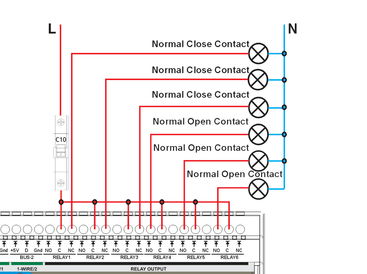
- Each relay has COM / NO / NC terminals
- Use NO for default OFF loads
- Use NC for default ON loads
- ⚡ Loads may carry hazardous voltage
- Supports AC and DC switching (DC and inductive loads require derating)
⚠️ External protection rule: Every relay output MUST be protected by an external fuse or circuit breaker. The rated current of the protective device shall not exceed 3 A MAX per output (board/system limit).
⚠️ Common protection warning: If a single common fuse or circuit breaker is used to protect multiple relay outputs (as shown in the wiring example), the protective device shall NOT be sized by summing relay outputs. The rating of the common protective device shall not exceed 3 A MAX per output (board/system limit).
For inductive or DC loads (contactors, solenoids, motors), use appropriate suppression (RC snubbers, MOVs, or flyback diodes). Loads exceeding the recommended PCB current limit shall be switched using external contactors or wiring methods that bypass PCB copper paths.
Analog I/O (0–10V)
MiniPLC provides 4 analog inputs and 1 analog output with a standard 0–10V signal range. Use these channels for common sensors, transmitters, and control devices that accept/produce 0–10V signals.
Analog Inputs (AI) — 4 Channels
Analog Input Specifications
| Channel | Signal Range | Resolution | Description |
|---|---|---|---|
| AI #1 | 0–10V | 16-bit | Analog input 1 |
| AI #2 | 0–10V | 16-bit | Analog input 2 |
| AI #3 | 0–10V | 16-bit | Analog input 3 |
| AI #4 | 0–10V | 16-bit | Analog input 4 |
Analog Input Wiring
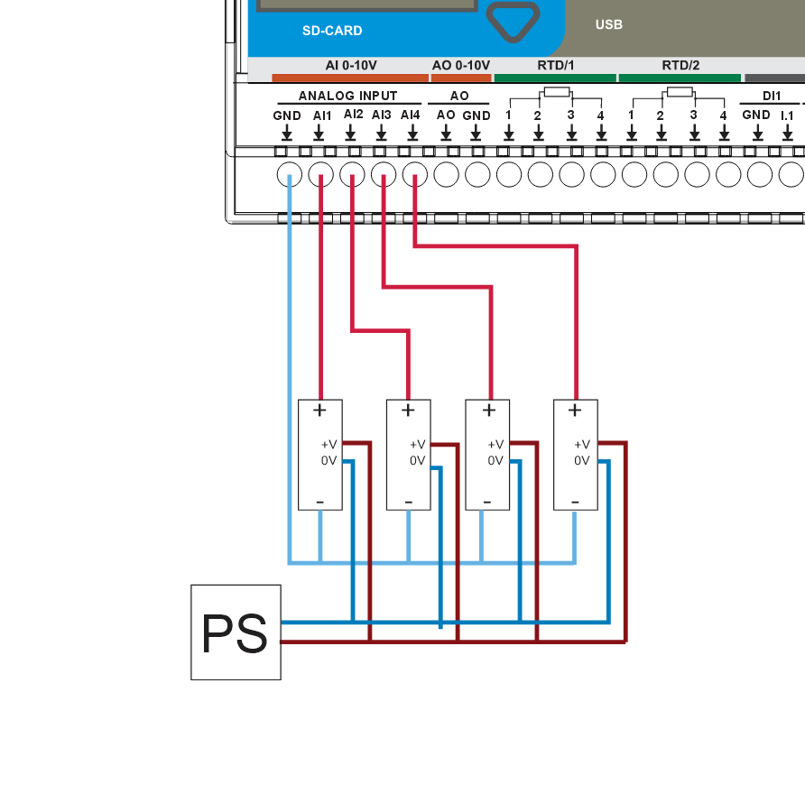
Wiring Checklist (AI)
- Signal: 0–10V
- Reference: connect sensor 0V to AI GND
- Use a shared 0V/common ground between sensors and MiniPLC
- For long runs, use a twisted pair (Signal + GND)
- Keep analog wiring away from relay outputs and mains/AC wiring
Analog Output (AO) — 1 Channel
Analog Output Specifications
| Channel | Signal Range | Resolution | Description |
|---|---|---|---|
| AO #1 | 0–10V | 12-bit (4096 steps) | Analog output for control signals |
Analog Output Wiring
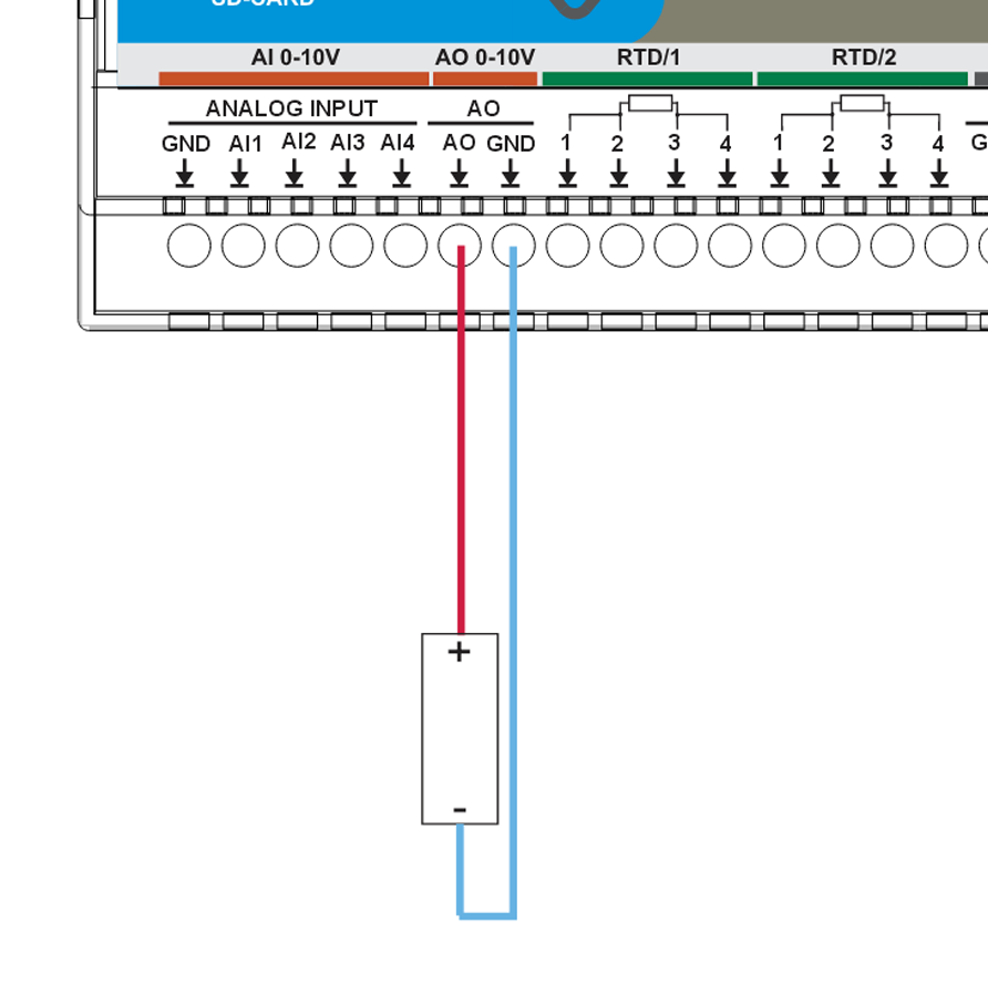
Wiring Checklist (AO)
- Signal: 0–10V
- Reference ground: AO GND
- Use a twisted pair (AO + AO GND) for long runs
- Keep AO wiring away from power switching and motor/VFD cables
- Typical use cases: analog setpoints (VFD speed), valve/actuator positioning, controller reference signals.
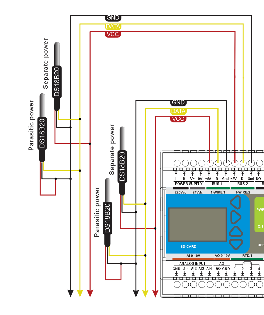
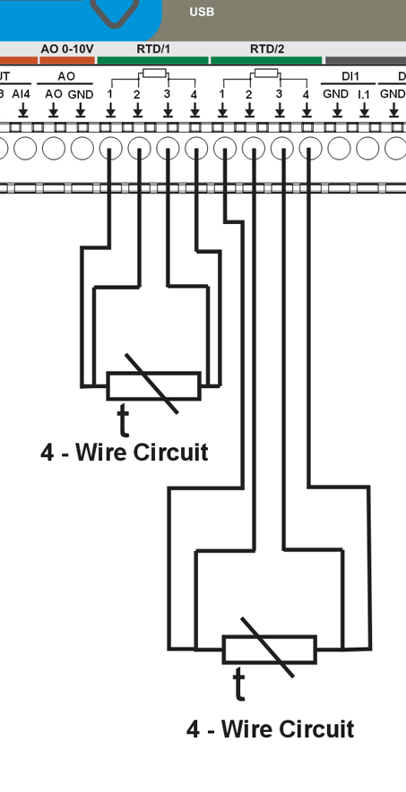
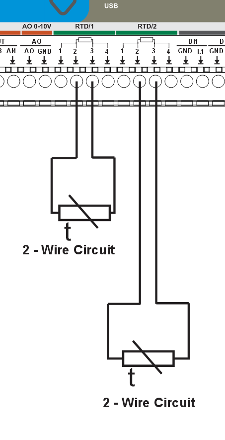
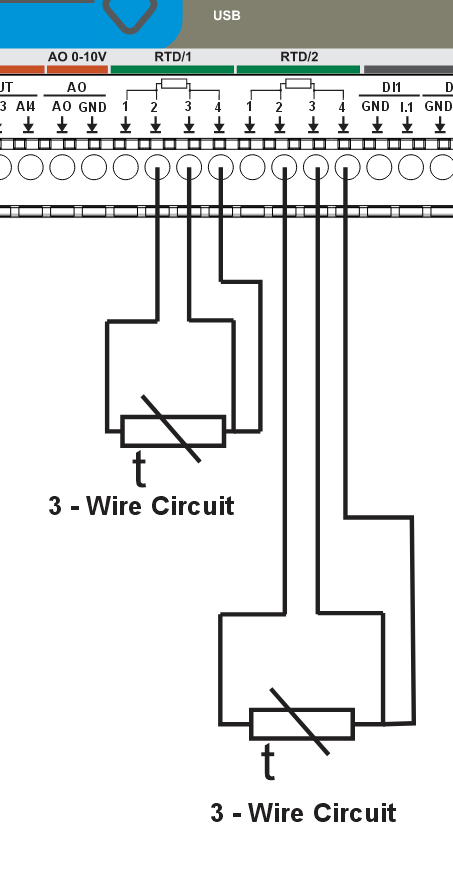
Temperature Inputs
MiniPLC supports RTD sensors (PT100/PT1000) and 1-Wire temperature sensors (DS18B20 or compatible) for reliable cabinet and process temperature monitoring.
Temperature Input Specifications
| Type | Channel | Sensor / Interface | Range | Accuracy |
|---|---|---|---|---|
| RTD | RTD #1 | PT100/PT1000 (SPI front-end) | -200°C to +850°C | ±0.5°C typical |
| RTD | RTD #2 | PT100/PT1000 (SPI front-end) | -200°C to +850°C | ±0.5°C typical |
| 1-Wire | BUS #1 | DS18B20 (or compatible) | -55°C to +125°C | ±0.5°C |
| 1-Wire | BUS #2 | DS18B20 (or compatible) | -55°C to +125°C | ±0.5°C |
Wiring Examples
User Interface
| Component | Quantity | Control | Description |
|---|---|---|---|
| Front Panel Buttons | 4 | PCF8574A:0-3 | Tactile buttons for local control |
| User LEDs | 3 | PCF8574A:4-6 | Configurable indicator LEDs |
| Status LED | 1 | PCF8574A:7 | System status indicator |
| OLED Display | 1 | I²C (0x3C) | 128×64 pixel SH1106 display |
| Buzzer | 1 | GPIO2 | Audible alarm/notification |
Features:
- Buttons can be mapped to toggle relays, trigger scenes, or custom actions
- LEDs can show relay status, system state, or custom patterns
- OLED displays time, sensor readings, and system status
- Buzzer provides audible feedback for alarms or notifications
Communication & Protocols
- Modbus RTU (RS-485) – UART-based communication for expansion modules and field devices
- Wi-Fi – ESP32 integrated (Improv onboarding supported)
- Ethernet – Optional via LAN8720 PHY
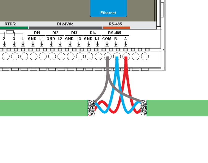
RS-485 Communication (Modbus RTU)
The MiniPLC provides a half-duplex RS-485 interface with integrated protection and fail-safe biasing. The interface is available on the A / B / COM terminals.
Hardware Features:
- RS-485 transceiver: MAX485 (half-duplex)
- Fail-safe biasing network on A/B (idle state defined)
- Common-mode choke for EMI suppression
- TVS surge and ESD protection on A/B/COM
- Resettable PTC fuses on A and B lines
- Bidirectional logic level shifting between MCU and transceiver
RS-485 Wiring
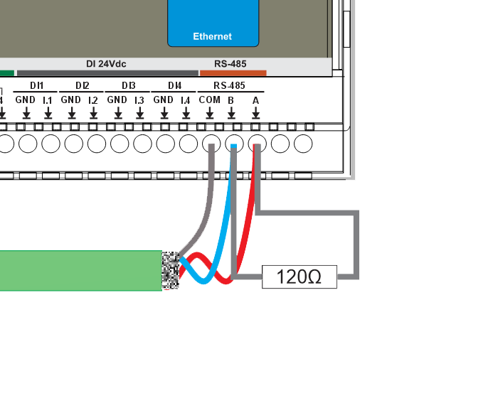
Termination & Biasing
- Terminate with 120 Ω only at the two ends of the line.
- Do not terminate intermediate devices.
- Fail-safe biasing is already provided inside the MiniPLC.
COM / Reference Ground
- Connect COM between all RS-485 nodes.
- This limits common-mode voltage and prevents communication faults.
Power Supply for Extension Modules
- Recommended: Use the same power supply for MiniPLC and all RS-485 extension modules.
- Distribute power in a star topology from the PSU.
- If separate PSUs are used, connect 0V references together at one point (unless the extension module is galvanically isolated).
A common 0V reference prevents RS-485 common-mode voltage errors and communication faults.
Tip: Cable recommendations, shield bonding, and routing rules are defined in the Cable Recommendations & Shield Grounding section below.
Cable Recommendations & Shield Grounding
This section applies to Analog (0–10V), Temperature (RTD / 1-Wire), and RS-485. Use shielded, twisted constructions and bond shields correctly to reduce EMI and ground-loop issues.
General Routing Rules
- Route low-level signal cables (Analog/RTD/1-Wire/RS-485) separately from mains, relay outputs, contactors, VFD motor cables, and power wiring.
- If crossing power cables is unavoidable, cross at 90°.
- Keep cable runs as short as practical and avoid parallel runs with high-current conductors.
Analog (0–10V) Cable
- Construction: twisted pair (Signal + GND) per channel
- Shielding: overall shield (standard) or individually shielded pairs (high-EMI)
- Examples: J-Y(ST)Y (overall shield) or LI2YCY PIMF (shielded twisted pairs; one pair per channel)
Temperature Cable
RTD (PT100/PT1000)
- Recommended: shielded multi-core for 2/3-wire; shielded pairs for best accuracy (4-wire)
- Examples: J-Y(ST)Y (overall shield) or LI2YCY PIMF (pairs; e.g. 2×2×0.50 for 4-wire)
1-Wire (DS18B20)
- Recommended: shielded 3-core ( +5V / DATA / GND ) for typical installations
- High-EMI / long runs: shielded pairs + overall shield (e.g. LI2YCY PIMF 2×2×0.50)
- Topology: daisy-chain (bus). Avoid star wiring.
- Stubs: keep sensor stubs ≤ 0.5 m.
- Pull-up (DATA): 4.7 kΩ typical; 2.2–3.3 kΩ for long/heavy loads.
RS-485 Cable
- Construction: twisted pair for A/B
- Characteristic impedance: 120 Ω (recommended)
- Shielding: overall shield is recommended in cabinets; use individually shielded pairs + overall shield in high-EMI
- Examples: J-Y(ST)Y 2×2×0.5 mm² or LI2YCY PiMF 2×2×0.50
- Use one twisted pair for A/B. Use the second pair for COM (0V reference) or spare.
Shield Grounding
- Default recommendation: bond cable shield(s) to cabinet PE/EMC ground at the PLC end only.
- Do not connect shields to signal terminals (AI/AO/RTD/1-Wire/RS-485 A/B/COM).
- If both ends are in equipotential bonded cabinets, shields may be bonded at both ends using proper 360° clamps.
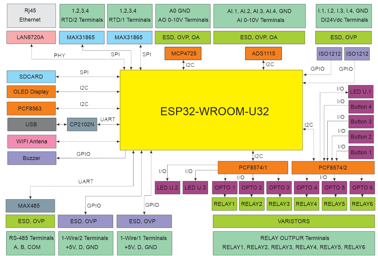
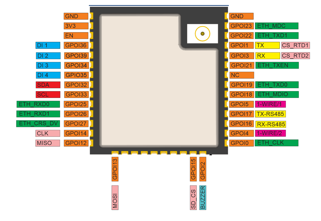
System Architecture & Pinout
Compliance & Certifications
The HomeMaster MiniPLC is CE marked and designed to comply with the applicable European Union directives. The manufacturer, ISYSTEMS AUTOMATION (HomeMaster brand), maintains the technical documentation and a signed EU Declaration of Conformity (DoC).
EU Directives
EMC 2014/30/EU · LVD 2014/35/EU · RED 2014/53/EU · RoHS 2011/65/EU
Harmonised Standards
| Area | Standards |
|---|---|
| EMC | EN 61000-6-1 (Immunity) · EN 61000-6-3 (Emissions) |
| Electrical Safety | EN 62368-1 |
| Radio | EN 300 328 · EN 301 489-1 · EN 301 489-17 |
| RoHS | EN IEC 63000 |
Radio
The product integrates a pre-certified ESP32 Wi-Fi radio module (2.4 GHz). Final product conformity with the Radio Equipment Directive is demonstrated by the maintained technical documentation and conformity assessment of the complete device.
Safety notice
L / N: hazardous voltage · 24 V DC: SELV · Qualified personnel only
Related products
These other products might interest you