


DIO-430-R1 Relay module 3-channel
The DIO-430-R1 is an industrial-grade digital I/O expansion module designed for relay switching and input monitoring over RS485 Modbus networks. Built for smart buildings and control systems, it provides opto-isolated inputs, high-current relays, and flexible local logic in a compact DIN-rail enclosure.
The module integrates seamlessly with the HomeMaster ecosystem and works as a Modbus slave device with MiniPLC, MicroPLC, Home Assistant, ESPHome, and industrial PLC systems.
Display Name:
DIO-430-R1 Relay module 3-channel
DIO-430-R1 — Module for Smart I/O Control
HOMEMASTER – Modular control. Custom logic.
1. Introduction
The DIO-430-R1 is a configurable smart digital I/O module designed for digital input monitoring and relay-based output control in building automation, lighting, HVAC, alarms, and general control systems.
It offers 4 opto-isolated digital inputs, 3 high-current SPDT relays, 3 user buttons, and 3 configurable user LEDs. All I/O channels are individually configurable, allowing flexible logic such as toggle, pulse, manual override, and alarm indication.
It connects via RS-485 (Modbus RTU) to a MicroPLC, MiniPLC, or any compatible controller, and can also integrate with Home Assistant (ESPHome) or SCADA/PLC systems.
Configuration and diagnostics are performed through a driverless Web Serial interface via USB-C, using the browser-based WebConfig Tool. The module supports both master-controlled and standalone local logic modes.
| Subsystem | Qty | Description |
|---|---|---|
| Digital Inputs | 4 | Opto-isolated, dry contact compatible, noise-protected |
| Relays | 3 | SPDT (NO/NC), 16 A rated, dry contacts |
| LEDs | 3 | Configurable: Steady or Blink modes, linked to relays |
| Buttons | 3 | User-configurable for override or reset |
| Modbus RTU | Yes | RS-485 interface (Configurable: Addr 1–255, 9600–115200 baud) |
| USB-C | Yes | WebConfig tool access via Web Serial (Chrome/Edge) |
| Power | 24 V DC | Fused input, reverse-polarity and surge protected |
| MCU | RP2350 | Dual-core, with QSPI flash, USB, UART, LittleFS |
| Protection | TVS, PTC | ESD, surge, and short-circuit protection on I/O and power |
System Role & Communication
The module communicates over the RS-485 Modbus RTU bus, using A/B differential lines and a shared COM/GND reference. It supports poll-based communication, where a master device reads input states and writes relay commands.
All configuration — including input-to-relay mapping, LED modes, and button logic — is stored persistently in internal flash via LittleFS and can be changed live through USB-C + WebConfig.
Factory default communication settings:
- Modbus Address:
3 - Baud Rate:
19200 - Parity:
None - Stop Bits:
1
The module’s logic (input→relay mapping, LED modes, button behavior) is stored persistently in internal flash via LittleFS, and settings can be changed live using USB-C + WebConfig.
2. DIO-430-R1 — Technical Specification
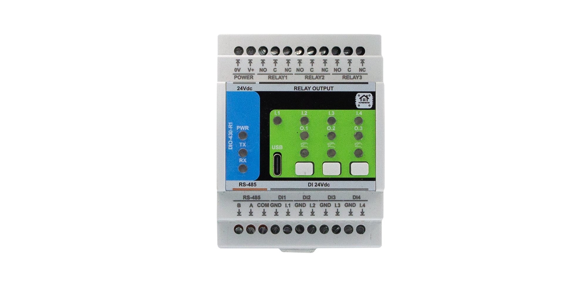
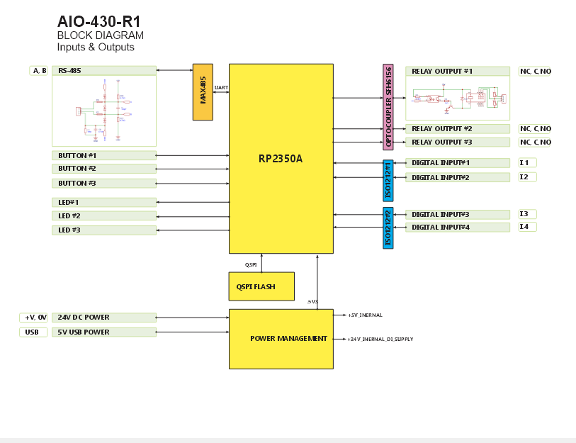
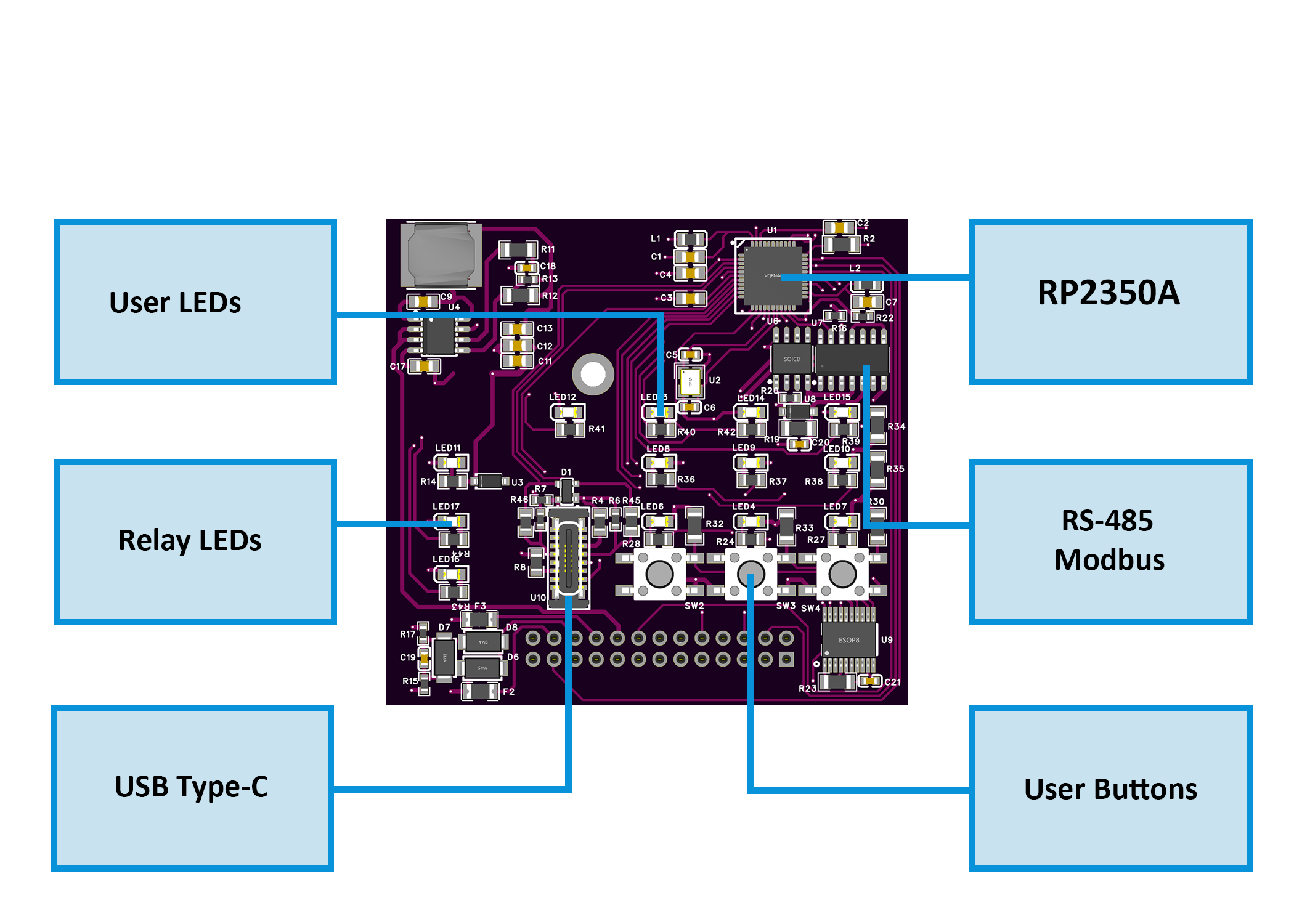
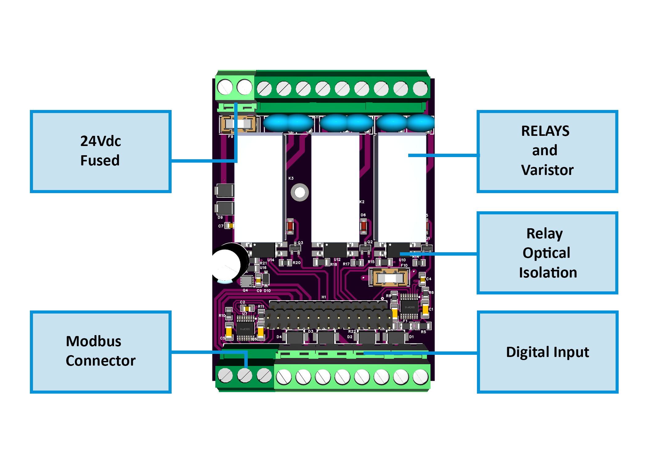
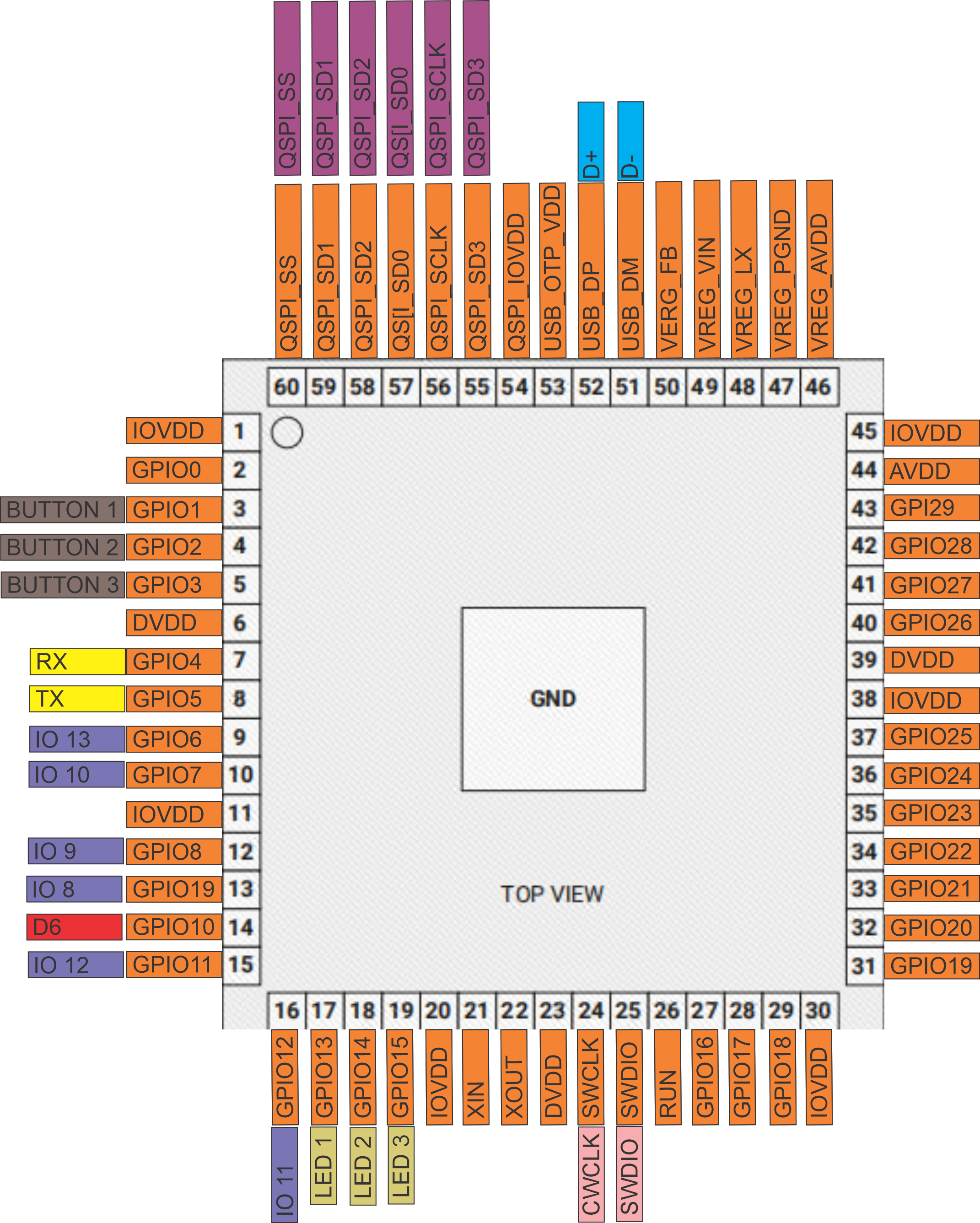
2.1 Diagrams & Pinouts
System overview, board callouts, and pin mapping:
2.2 I/O and Electrical Summary
| Interface | Qty | Description |
|---|---|---|
| Digital Inputs | 4 | Galvanically isolated (ISO1212 class). Supports dry contacts or 24 V signals. PTC + TVS per channel. |
| Relay Outputs | 3 | SPDT (NO/NC/COM), 16 A dry contacts. Use RC/MOV snubbers or interposing contactors for inductive/mains loads. |
| User LEDs | 3 | Configurable (Steady/Blink). Follow relay or logic status. |
| Buttons | 3 | Momentary. Configurable for relay override/toggle. |
| RS-485 (Modbus RTU) | 1 | A/B/COM terminals. Daisy-chain topology. 120 Ω termination at both ends. |
| USB-C | 1 | Web Serial setup, diagnostics, and firmware flashing (ESD-protected). |
| Power Input | 1 | 24 V DC SELV. Reverse-polarity + surge protected. |
Electrical Ratings
| Parameter | Min | Typ | Max | Unit | Notes |
|---|---|---|---|---|---|
| Supply Voltage | 22 | 24 | 28 | V DC | SELV/PELV input |
| Logic Consumption | – | 1.5 | 3.0 | W | Excludes relay loads |
| Digital Input Range | 0 | 24 | 30 | V DC | Isolated, noise-protected |
| Relay Contact Current | – | – | 16 | A | SPDT dry contacts |
| Relay Contact Voltage | – | – | 250 | V AC | or 30 V DC max |
| RS-485 Data Rate | – | 19.2 | 115.2 | kbps | Default 19200 8N1 |
| USB-C Voltage | 4.75 | 5.0 | 5.25 | V DC | Service only |
| Operating Temp. | 0 | – | 40 | °C | ≤ 95 % RH, non-condensing |
Power budgeting: logic + LEDs + up to 3 relay coils + sensor loads → add ≥ 30 % PSU headroom.
2.3 Connectors & Terminal Map
| Block | Pins | Function | Notes |
|---|---|---|---|
| POWER | 0V, V+ | 24 V DC input | Reverse/surge protected |
| RELAY 1-3 | NO, C, NC | SPDT contacts | Add RC/MOV for inductive loads |
| DI 1-4 | INx, GNDx | Isolated digital inputs | 24 V field or dry contact |
| RS-485 | B, A, COM | Modbus RTU bus | Terminate 120 Ω at ends |
| USB-C | D+, D−, VBUS, GND | Setup / Service port | Not for field powering |
2.4 Reliability & Protection
- Reverse-path diode + high-side MOSFET on 24 V input.
- Local PTC + TVS protection on field interfaces.
- Relay drivers opto-isolated; RC/MOV suppression recommended.
- RS-485 with TVS, series protection, and fail-safe biasing.
- USB-C ESD-protected; CC resistors per spec.
- Non-volatile flash with auto-save after configuration changes.
2.5 Functional Overview
- Modbus RTU slave (factory Addr 3, 19200 8N1; configurable 1–255, 9600–115200).
- Inputs → Relays: per-input Enable/Invert/Action (
None/Toggle/Pulse) and Target (R1–R3orAll). - Buttons: assignable to relay override (toggle).
- LEDs: configurable Steady/Blink following relay status.
- Setup via WebConfig: USB-C → Chrome/Edge; set comms and I/O mapping.
- Persistent config: stored in LittleFS and restored on boot.
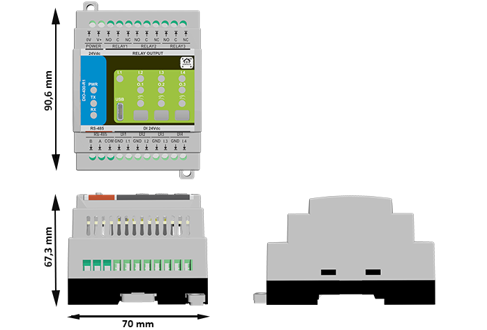
2.6 Mechanical & Environmental
| Property | Specification |
|---|---|
| Mounting | DIN-rail EN 50022 (35 mm) |
| Enclosure | PC/ABS V-0, panel mount |
| Dimensions | 70 × 90.6 × 67.3 mm (W × H × D) |
| Terminals | Pluggable 5.08 mm, 26–12 AWG (≤ 2.5 mm²), 0.5–0.6 Nm |
| Ingress Protection | IP20 (panel interior) |
| Operating Temp | 0–40 °C, ≤ 95 % RH (non-condensing) |
2.7 Standards & Compliance
| Standard / Directive | Description |
|---|---|
| Ingress Rating | IP20 (panel-mount only) |
| Altitude | ≤ 2000 m |
| Environmental | RoHS / REACH compliant components |
3. Use Cases
The DIO‑430‑R1 supports both lighting and motor/pump control — making it ideal for mixed automation tasks in smart homes, greenhouses, HVAC, and industrial setups.
Below are 3 versatile examples combining both types of loads.
3.1 Staircase Light with Motion Sensor + Circulation Pump
Automatically turns ON a staircase light and a circulation pump when motion is detected.
Setup Instructions:
- Set IN1 to
Action = Pulse,Target = Relay 1(light). - Set IN2 to
Action = Pulse,Target = Relay 2(pump). - Enable Relay 1 for the staircase lighting.
- Enable Relay 2 for the circulation pump.
- Set LED 1 =
Blink, source =Relay 1. - Set LED 2 =
Steady, source =Relay 2.
3.2 Manual Light + Fan Override (Wall Panel)
Wall-mounted buttons allow users to toggle lights and exhaust fans independently.
Setup Instructions:
- Assign Button 1 →
Relay 1 override (toggle)→ Room Light - Assign Button 2 →
Relay 2 override (toggle)→ Ventilation Fan - Enable both Relay 1 and Relay 2.
- Set LED 1 and LED 2 to
Steady, following respective relays. - Optionally use Modbus Coils
200–201for remote control.
3.3 Greenhouse Light + Irrigation Pump Automation
Lights and irrigation are controlled via digital inputs or remotely from a PLC.
Setup Instructions:
- IN3 →
Toggle, Target =Relay 1→ Grow Light - IN4 →
Pulse, Target =Relay 2→ Irrigation Pump - Enable Relay 1 and Relay 2.
- Assign Button 3 to
Relay 2 override (toggle)for manual watering. - Set LED 1 =
Steady(light status), LED 2 =Blink(pump running).
4. Safety Information
These guidelines apply to the DIO-430-R1 I/O module. Ignoring them may result in equipment damage, system failure, or personal injury.
⚠️ SELV/PELV Domains Only
- The DIO-430-R1 operates entirely within SELV/PELV low-voltage domains (e.g., 24 V DC, RS-485, USB 5 V).
- Do not connect mains voltage to any terminal. Use interposing contactors/PSUs for mains loads.
- Respect isolation boundaries: never bridge logic GND with isolated field grounds (e.g., GND_ISO / FGND).
- Connect sensor returns only to the isolated field ground; connect RS-485 COM/GND only within the same SELV domain.
4.1 General Requirements
| Requirement | Detail |
|---|---|
| Qualified Personnel | Installation and servicing must be done by qualified personnel familiar with 24 V control systems and RS-485. |
| Power Isolation | Disconnect the 24 V DC input before wiring. Lockout/tagout where applicable. |
| Environmental Limits | Mount in a clean, sealed enclosure; avoid condensation, conductive dust, or vibration. |
| Grounding | Bond the panel to PE. Keep RS-485 COM/GND shared with the controller side. |
| Voltage Compliance | SELV only on all terminals. Follow relay contact ratings on the product label/datasheet. Use upstream fusing and surge protection. |
4.2 Installation Practices
| Task | Guidance |
|---|---|
| ESD Protection | Handle by the enclosure/edge only. Use an antistatic wrist strap when the board is exposed. |
| DIN Rail Mounting | Mount securely on 35 mm DIN rail inside an IP-rated cabinet. Leave cable slack for strain relief. |
| Wiring | Use correct wire gauge and torque terminal screws. Separate power, DI, relay, and RS-485 harnesses. |
| Isolation Domains | Respect isolation: do not bridge logic GND to isolated field grounds (e.g., GND_ISO/FGND). Keep analog/sensor returns on the isolated side. |
| Commissioning | Before power-up, verify polarity, relay NO/NC routing, RS-485 A/B orientation and termination. |
4.3 I/O & Interface Warnings
🔌 Power
| Area | Warning |
|---|---|
| 24 V DC Input | Use a clean, fused SELV supply. Reverse-polarity protection exists but may disable the module when triggered. |
| Sensor Rail | Power sensors from a SELV rail. Observe polarity. Fuse external branches as required. |
| Surge/Noise | In noisy panels, add upstream surge/EMI suppression and keep high-current wiring away from control wiring. |
⏽ Inputs (Digital)
| Area | Warning |
|---|---|
| Type | Dry contact / 24 V signaling only, per your standard. Do not inject mains or undefined levels. |
| Isolation | Inputs are isolated from logic. Keep sensor returns on the field/isolated domain; do not bond to logic GND. |
| Debounce | Firmware provides debounce, but route away from contactors/VFDs and use shielded/twisted pairs for long runs. |
| Polarity | Configure invert/action in WebConfig; verify state transitions after wiring. |
⚙️ Relays (Outputs)
| Area | Warning |
|---|---|
| Contact Type | SPDT (NO/NC/COM) dry contacts. Follow the contact rating on the device label/datasheet. |
| Inductive Loads | For motors/solenoids/contactors, add an RC snubber or MOV at the load. Consider interposing relays/ contactors for higher power. |
| Separation | Keep relay load wiring physically separate from signal wiring. De-energize before servicing. |
| Verification | After wiring, verify NO/NC behavior and load polarity before enabling automation. |
🖧 RS-485 (Modbus RTU)
| Area | Warning |
|---|---|
| Topology | Use twisted pair; daisy-chain (no stubs). Terminate with 120 Ω at both physical ends. |
| Polarity | Maintain A/B polarity consistently. Share COM/GND reference between nodes (same SELV domain). |
| EMC | Route away from VFDs, contactors, and mains bundles. Use shielded cable in high-EMI environments. |
| Protection | Port includes protection, but good wiring practice is still required to avoid transients. |
🔌 USB-C (Front / Setup)
| Area | Warning |
|---|---|
| Purpose | Setup & maintenance only (WebConfig / firmware). Not intended for powering field devices. |
| ESD/EMI | Avoid hot-plugging in high-EMI areas. Use a grounded service laptop. Disconnect after commissioning. |
🔆 Front Panel (Buttons & LEDs)
| Area | Warning |
|---|---|
| Buttons & LEDs | Buttons can override relays; document operating procedures. Lock out overrides for safety-critical installs. |
🛡️ Shielding & EMC
| Area | Recommendation |
|---|---|
| Cable Shields | Terminate shields at one end (typically the PLC/controller). Keep runs short and away from high-voltage/EMI sources. |
✅ Pre-Power Checklist
- No bridge between logic GND and isolated GND_ISO/FGND
- A/B polarity and 120 Ω termination confirmed at bus ends
- not exceed the contact rating; snubbers added for inductive loads
- dry contact/SELV only; sensor polarity and returns verified
5. Installation & Quick Start
The DIO-430-R1 joins your system over RS-485 (Modbus RTU). Setup has two parts:
- Physical wiring, 2) Digital configuration (WebConfig → optional PLC/ESPHome).
5.1 What You Need
| Category | Item / Notes |
|---|---|
| Hardware | DIO-430-R1 — DIN-rail module with 4× DI, 3× SPDT relays, 3× buttons, 3× LEDs, USB-C, RS-485. |
| Controller (master) | HomeMaster MiniPLC/MicroPLC or any Modbus RTU master. |
| 24 VDC PSU (SELV) | Regulated 24 VDC; size for logic + relay coils + sensors; inline panel fuse/breaker. Power input stage includes fuse/TVS/reverse-polarity protection. |
| RS-485 cable | Twisted pair for A/B + COM/GND reference, 120 Ω termination at both ends of the trunk. |
| USB-C cable | For WebConfig via a Chromium browser (service/commissioning). |
| Software | Chromium-based browser with Web Serial (Chrome/Edge). Web page exposes Address/Baud + I/O mapping. |
| Field I/O | Dry contacts to DI1…DI4 (isolated front-end per channel). Relays (NO/NC/COM) drive LV loads or interposing contactors; add RC/MOV snubbers for inductive loads. |
Quick path: mount → wire 24 VDC + RS-485 A/B/COM → connect USB-C → WebConfig: set Address/Baud + map inputs → relays/LEDs → disconnect USB → hand over to controller.
5.2 Power
The module uses 24 VDC primary. Onboard regulation provides 5 V → 3.3 V for logic; DI front-end is isolated.
5.2.1 Supply Types
- 24 VDC DIN-rail PSU → 24Vdc(+) / 0V(–) power terminals (top row: POWER).
- Sensor side (DI) — isolated input receivers accept field signals; feed your sensors from the 24 V field rail and return to the DI GND pins (per-channel). Do not back-power logic from sensor rails.
5.2.2 Sizing (rule of thumb)
Account for:
- Base electronics + LEDs
- Relay coils (up to 3 simultaneously)
- Sensor rails (DI field side, if powered from the same 24 V source)
Size PSU for worst-case relays + sensors, then add ≥30 % headroom.
5.2.3 Power Safety
- Correct polarity; keep logic GND and DI field ground separate (respect isolation domains).
- Keep upstream fusing/breaker in place; the board also has input fuse/TVS/reverse-polarity MOSFET.
- Use snubbers on inductive loads; prefer interposing contactors for motors/pumps.
- De-energize before wiring; check shorts before power-up.
5.3 Networking & Communication
Runtime control is via RS-485 (Modbus RTU). USB-C is for local setup/diagnostics (Web Serial).
5.3.1 RS-485 (Modbus RTU)
Physical
- Terminals (lower front row): B, A, COM/GND → then DI and DI-GNDs. Maintain A/B polarity, share the COM/GND reference with the controller.
- Cable: Twisted pair (preferably shielded) for A/B + reference.
- Termination: 120 Ω at both physical ends of the trunk; avoid stubs.
Protocol
- Role: RTU slave; controller is master.
- Address: 1–255. Factory default: Address 3, 19200 8N1.
- Required: Dedicated 24 VDC power (bus is data-only).
Checklist
- A→A, B→B, COM→COM (GND ref).
- Two end terminations only; daisy-chain topology.
- Consistent A/B polarity end-to-end.
5.3.2 USB-C (WebConfig)
Purpose: Chromium (Chrome/Edge) Web Serial setup/diagnostics page.
Steps
- Connect USB-C to the module.
- Open the DIO-430-R1 WebConfig page and click Connect.
- Set Modbus Address & Baud (header shows Active Modbus Configuration).
- Configure Inputs / Relays / LEDs / Buttons; changes apply live and are saved to flash.
- Use Reset Device from the page if needed (dialog confirms).
If Connect is disabled: ensure Chromium + serial permission; close other apps that might hold the port.
5.4 Installation & Wiring
This section shows typical wiring for power, inputs, relays, RS-485, and the USB-C service port.
⚠️ Work on de-energized equipment only. Use SELV/PELV supplies for logic and field inputs. Mains on relay contacts must be wired by qualified personnel.
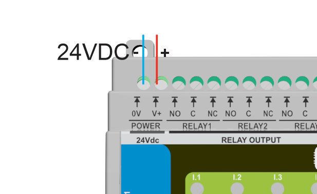
A) Power — 24 VDC (SELV)
Wire the regulated 24 VDC supply to the top POWER terminals: V+ and 0V.
Notes
- Keep V+/0V as a twisted pair; route away from motor cables/contactors.
- The module includes input protection (fuse/TVS/reverse-polarity MOSFET).
B) Digital Inputs (DI1…DI4)
Each input is isolated. Land the contact/sensor on INx with the paired GNDx return.
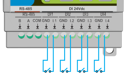
Tips
- Supports dry contacts or compatible 24 V field signals.
- Configure in WebConfig: Enabled/Invert, Action (
None / Toggle / Pulse), Control target (None / All / R1 / R2 / R3). - Keep field wiring shielded/twisted for long runs; terminate shield at one end only.
C) Relay Outputs (R1…R3)
Relays provide dry SPDT contacts (NO/NC/COM) for switching low-voltage loads or driving an interposing contactor for mains/inductive loads.
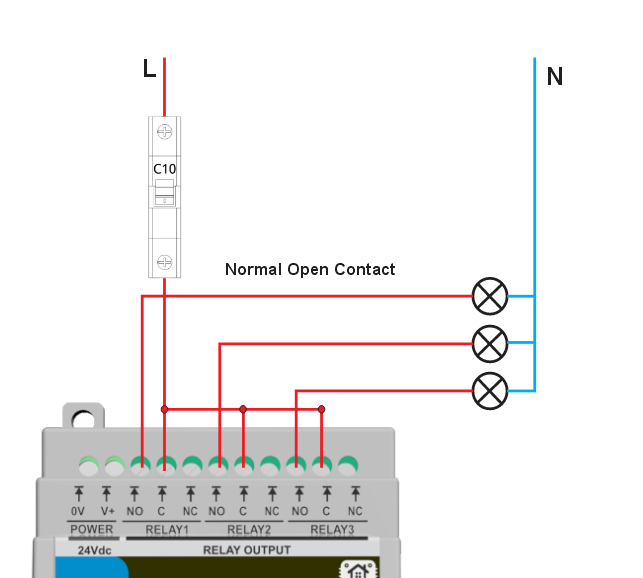
Best practices
- Add RC/MOV snubbers across inductive loads (fans, pumps, contactors).
- Keep load and logic wiring separated; observe conductor ratings and local code.
D) Sensor Rails (12 V / 5 V)
This module does not export auxiliary 12 V/5 V rails for field devices.
- Power sensors from your panel 24 V rail (or external rails as required).
- Return sensor commons to the matching DI GNDx terminals; do not bond field ground to logic GND.
E) RS-485 (Modbus RTU)
The lower left terminals expose B, A, and COM (GND). Use shielded twisted pair and daisy-chain topology.
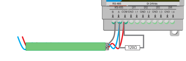
Checklist
- Wire A→A, B→B, and share COM/GND with the controller.
- Terminate the two physical bus ends with 120 Ω.
- Default protocol: Address 3, 19200 8N1 (change via WebConfig).
F) USB-C (Service / WebConfig)
- Use USB-C for commissioning and diagnostics only (Web Serial in Chrome/Edge).
- Not for powering field devices. Disconnect after setup and hand control to the RS-485 master.
5.5 Software & UI Configuration
Use the WebConfig page (USB-C + Chrome/Edge) to set Modbus comms and map I/O. Changes apply immediately and are saved to flash.
Screens shown below are from the DIO-430-R1 WebConfig.
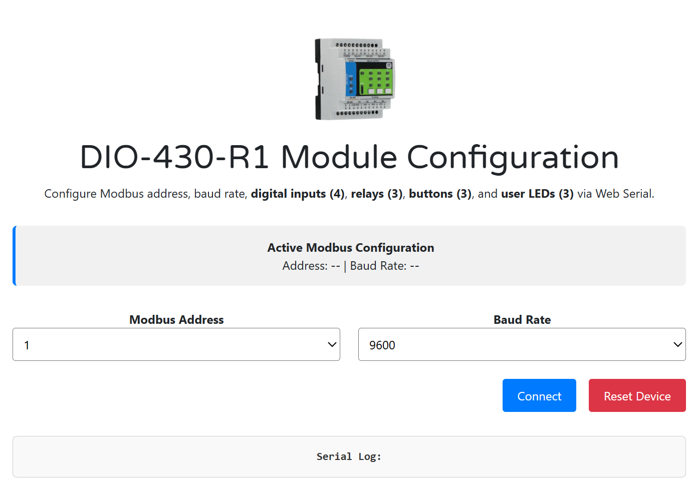
A) WebConfig setup (Address & Baud)
- Connect the module via USB-C → open the WebConfig page → click Connect.
- In Modbus Address, choose 1–255 (factory default 3).
- In Baud Rate, select 9600–115200 (factory default 19200 8N1).
- Confirm the Active Modbus Configuration banner updates (Address/Baud).
Default values (Addr 3, 19200 8N1) are also noted in the module docs.
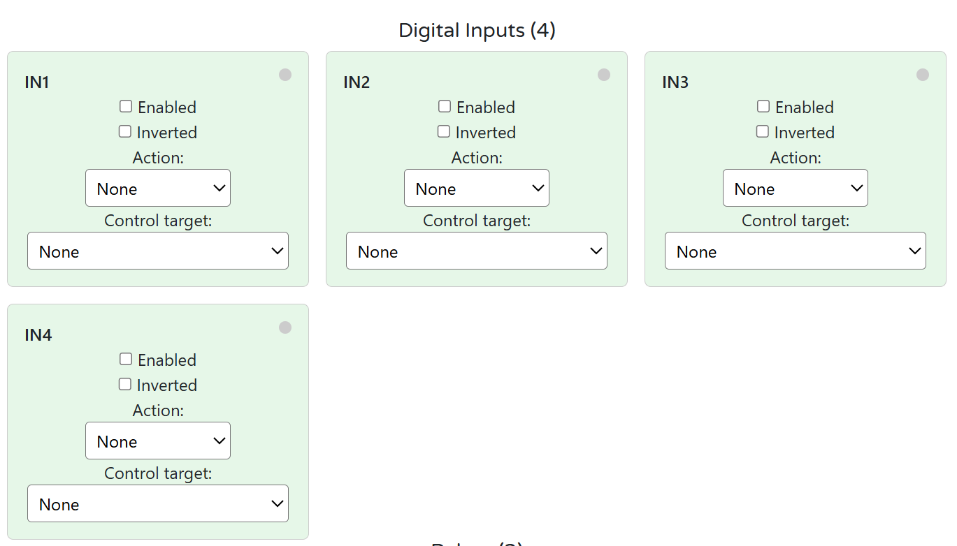
B) Inputs — enable / invert / group (control target)
Each IN1…IN4 card provides:
- Enabled: include the input in logic.
- Inverted: logical inversion.
- Action:
None / Toggle / Pulse. - Control target:
None / Control all / Relay 1 / Relay 2 / Relay 3.
This matches the firmware’s input options and allows direct mapping from inputs to one or more relays without a PLC.
Tips
- Use Toggle to latch a relay on each press; Pulse for momentary actions (timers handled by controller if needed).
- For “group” behavior, select Control all to operate Relays 1–3 together.
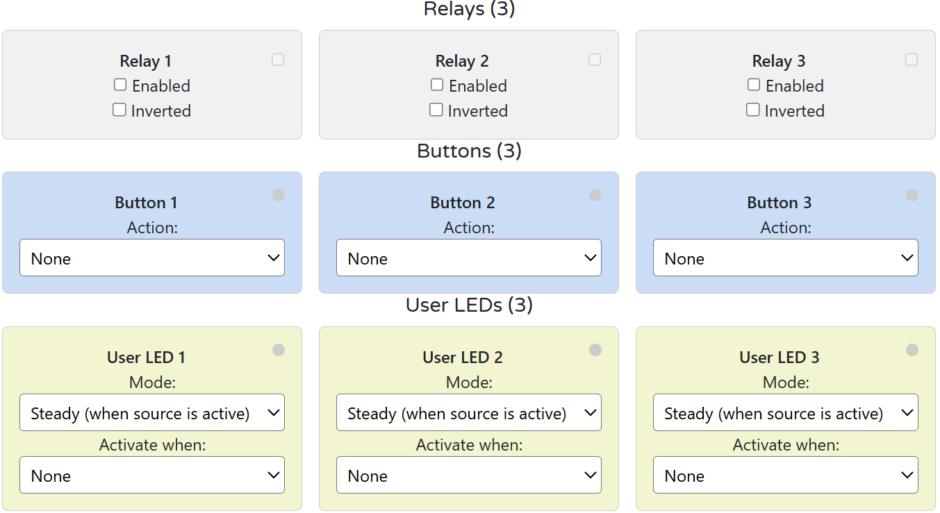
C) Relays — logic mode (group/manual)
For Relay 1–3:
- Enabled: relay is controllable.
- Inverted: invert drive polarity (use only if required by wiring).
Logic modes in practice
- Group control: Achieve via Input Control target = Control all (see Inputs section).
- Manual / local override: Assign Buttons (below) to toggle a specific relay even when the PLC also controls it.
D) LED and Button mapping
Buttons (3)
- Action: choose
Noneor Relay override (toggle) for Relay 1/2/3. This provides local/manual control without a PLC.
User LEDs (3)
- Mode:
SteadyorBlink(active when source is ON). - Activate when: select the source relay to follow (e.g., LED1 foll
5.6 Getting Started (3 Phases)
Phase 1 — Wire
- 24 VDC to V+ / 0V (GND) (top POWER terminals)
Use a regulated SELV supply; keep pairs twisted. - Digital inputs (IN1–IN4): dry contacts → INx / GNDx
Respect isolation domains; do not bridge logic GND ↔ field GND. - Relay outputs (R1–R3): COM / NO / NC
Prefer interposing contactors for motors/pumps; add RC/MOV snubber on inductive loads. - RS-485: A / B / COM (GND)
Shielded twisted pair; daisy-chain; terminate bus ends with 120 Ω. - USB-C (service): for WebConfig only (no field powering).
👉 See: Installation & Quick Start
Phase 2 — Configure (WebConfig)
- Open
https://www.home-master.eu/configtool-dio-430-r1in Chrome/Edge. - Connect USB-C → Select port → Connect.
- Set:
- Modbus Address / Baud (default: Addr 3, 19200 8N1)
- Inputs: Enable / Invert / Action (
None / Toggle / Pulse) / Control target (None / All / R1 / R2 / R3) - Relays: Enable (optional Invert)
- Buttons: map to Relay override (toggle) (R1/R2/R3)
- User LEDs: Mode (
Steady / Blink) + Activate when (follow a relay)
- Click Reset Device if prompted; settings auto-save to flash.
👉 See: WebConfig UI
Phase 3 — Integrate (Controller)
- Connect controller (MiniPLC/MicroPLC/PLC/SCADA/ESPHome) via RS-485.
- Match address and baud.
- Poll:
- Discrete inputs for DI states and relay states (per your mapping)
- Write:
- Coils to control relays (e.g., R1/R2/R3 ON/OFF)
- Use with:
- HomeMaster MicroPLC / MiniPLC
- ESPHome / SCADA / PLC
👉 See: Modbus RTU Communication & Integration Guide
✅ Verify
| Area | What to Check |
|---|---|
| LEDs | PWR = ON; TX/RX blink during RS-485 traffic |
| Inputs | Toggling a wall switch/sensor changes INx state in WebConfig/Modbus |
| Relays | Coil writes toggle R1–R3; loads switch correctly; snubber installed for inductive loads |
| Address/Baud | Controller reads module at the configured address/baud without errors |
| Isolation | No unintended bond between logic GND and DI field GNDx |
6. Modbus RTU Communication
Role: RTU slave (controller is master)
Defaults: Address 3, 19200 8N1 (change in WebConfig → Modbus)
Addressing shown below uses zero-based offsets (e.g., Holding Reg
40000= offset0).
If your master uses 1-based display (e.g., 40001), add +1 to the register number.
6.1 Address Range & Map (Overview)
| Type | Range (offsets) | Purpose |
|---|---|---|
| Coils (0x) | 00000…00031 |
Relay commands, device control |
| Discrete Inputs (1x) | 10000…10031 |
DI states, relay echo states |
| Input Registers (3x) | 30000…30031 |
Read-only status (masks, counters) |
| Holding Registers (4x) | 40000…40063 |
Config & runtime parameters (DI actions/targets, relay/LED/button settings, comms) |
6.2 Coils (0x) — Commands
| Coil | Name | Description |
|---|---|---|
00000 |
R1_CMD | Relay 1 ON/OFF (write 1/0) |
00001 |
R2_CMD | Relay 2 ON/OFF |
00002 |
R3_CMD | Relay 3 ON/OFF |
00010 |
SAVE_CFG | Persist current settings to flash (write 1) |
00011 |
RESET | Soft reset device (write 1) |
Coils drive relays regardless of input mappings (local buttons still work as overrides).
6.3 Discrete Inputs (1x) — States
| DI | Name | Description |
|---|---|---|
10000 |
DI1_STATE | Digital Input 1 (after invert option) |
10001 |
DI2_STATE | Digital Input 2 |
10002 |
DI3_STATE | Digital Input 3 |
10003 |
DI4_STATE | Digital Input 4 |
10010 |
R1_STATE | Relay 1 actual state (echo) |
10011 |
R2_STATE | Relay 2 actual state |
10012 |
R3_STATE | Relay 3 actual state |
6.4 Holding Registers (4x) — Configuration & Runtime
6.4.1 Identity / Comms
| Reg | Name | R/W | Encoding | Notes |
|---|---|---|---|---|
40000 |
MODEL_ID | R | u16 | e.g., 0x0430 (DIO-430) |
40001 |
FW_BUILD | R | YYYYMM | Snapshot / build tag |
40002 |
MB_ADDR | R/W | u16 | 1…255 |
40003 |
MB_BAUD | R/W | enum | 0=9600,1=19200,2=38400,3=57600,4=115200 |
40004 |
MB_PARITY | R/W | enum | 0=None,1=Even,2=Odd (default 0) |
6.4.2 Digital Inputs (per-channel)
Action codes: 0=None, 1=Toggle (latched), 2=Pulse (momentary)
Target codes: 4=None, 0=Control all, 1=R1, 2=R2, 3=R3
| Reg | Name | R/W | Encoding | Notes |
|---|---|---|---|---|
40010 |
DI_EN_MASK | R/W | bitmask | bit0…3 → IN1…IN4 enable |
40011 |
DI_INV_MASK | R/W | bitmask | bit0…3 → IN1…IN4 invert |
40012 |
DI1_ACTION | R/W | u16 enum | 0/1/2 |
40013 |
DI2_ACTION | R/W | u16 enum | 0/1/2 |
40014 |
DI3_ACTION | R/W | u16 enum | 0/1/2 |
40015 |
DI4_ACTION | R/W | u16 enum | 0/1/2 |
40016 |
DI1_TARGET | R/W | u16 enum | 4/0/1/2/3 |
40017 |
DI2_TARGET | R/W | u16 enum | 4/0/1/2/3 |
40018 |
DI3_TARGET | R/W | u16 enum | 4/0/1/2/3 |
40019 |
DI4_TARGET | R/W | u16 enum | 4/0/1/2/3 |
6.4.3 Relays / Buttons / LEDs
| Reg | Name | R/W | Encoding | Notes |
|---|---|---|---|---|
40020 |
RLY_EN_MASK | R/W | bitmask | bit0…2 → R1…R3 enable |
40021 |
RLY_INV_MASK | R/W | bitmask | invert coil logic (rarely used) |
40022 |
BTN1_ACTION | R/W | u16 enum | 0=None, 5=R1 toggle, 6=R2 toggle, 7=R3 toggle |
40023 |
BTN2_ACTION | R/W | u16 enum | as above |
40024 |
BTN3_ACTION | R/W | u16 enum | as above |
40025 |
LED_MODE | R/W | bit-packed | bits0…1 = LED1 (0=Steady,1=Blink), bits2…3 = LED2, bits4…5 = LED3 |
6.4.4 Status / Diagnostics
| Reg | Name | R/W | Encoding | Notes |
|---|---|---|---|---|
40030 |
UPTIME_S_LO | R | u16 | lower 16 bits |
40031 |
UPTIME_S_HI | R | u16 | upper 16 bits (32-bit seconds) |
40032 |
ERR_CODE | R | u16 | 0=OK; non-zero = last error |
40033 |
FLAGS | R | bitmask | e.g., cfg-dirty, wd-reset (implementation-specific) |
Note: All configuration is usually done via WebConfig. The registers above are provided to enable controller-side provisioning and telemetry when needed.
6.5 Input Registers (3x) — Convenience (Read-only)
| Reg | Name | Encoding | Description |
|---|---|---|---|
30000 |
DI_STATE_MASK | bitmask | bit0…3 → IN1…IN4 (post-invert) |
30001 |
RLY_STATE_MASK | bitmask | bit0…2 → R1…R3 |
30002 |
BTN_STATE_MASK | bitmask | bit0…2 → B1…B3 (momentary) |
30003 |
LED_STATE_MASK | bitmask | bit0…2 → LED1…LED3 active |
6.6 Register Use Examples
A) Toggle a relay from a PLC
- Write
1to Coil00001(R2_CMD) → Relay 2 ON - Write
0to the same coil → Relay 2 OFF
B) Map IN3 to drive Relay 1 as a latched toggle
40010 (DI_EN_MASK)→ set bit2 = 1 (enable IN3)40011 (DI_INV_MASK)→ set bit2 = 0 (no invert)40014 (DI3_ACTION)→ write1(Toggle)40018 (DI3_TARGET)→ write1(R1)
C) Set Button 2 to local override of Relay 2
40023 (BTN2_ACTION)→ write6(R2 toggle)
D) Make LED1 blink when Relay 1 is active
- In
40025 (LED_MODE): set LED1 field to Blink (value1)
E) Change Modbus address & baud from the master
40002 (MB_ADDR)→ new address (1…255)40003 (MB_BAUD)→ new enum (e.g.,1for 19200)- Coil
00010 (SAVE_CFG)= 1, then00011 (RESET)= 1
6.7 Polling Recommendations
- Transport: RS-485, daisy-chain, 120 Ω terminators at both ends, share COM/GND reference.
- Rates:
- States (1x/3x): 5–10 Hz typical (100–200 ms) for DI/relay/LED masks.
- Coils (0x): write only on change; read-after-write or echo via
RLY_STATE_MASK. - Holding (4x): configure at commissioning; read occasionally (e.g., every 5–10 s).
- Framing: Prefer 19200 8N1 for mixed networks; increase only on short, low-noise trunks.
- Time-outs/Retries: 100–250 ms timeout, 2–3 retries; back-off on bus errors.
- Edge logic: If a PLC supervises latching/timers, set DI Action = Pulse; if you want module-local latching, set Action = Toggle.
7. ESPHome Integration Guide (MiniPLC/MicroPLC + DIO-430-R1)
Support status: ✔️ Supported via ESPHome
uart+modbus+modbus_controllerand a reusable package.
Module role: Modbus RTU slave on RS-485.
Defaults: Address 3, 19200 8N1 (change in WebConfig).
7.1 Minimal YAML (Controller side)
Use this on the MiniPLC/MicroPLC (ESPHome). It enables the RS-485 bus and imports a ready-made DIO package.
uart:
  id: uart_modbus
  tx_pin: 17
  rx_pin: 16
  baud_rate: 19200
  parity: NONE
  stop_bits: 1

modbus:
  id: modbus_bus
  uart_id: uart_modbus

packages:
  dio1:
    url: https://github.com/isystemsautomation/HOMEMASTER
    ref: main
    files:
      - path: DIO-430-R1/Firmware/default_dio_430_r1_plc/default_dio_430_r1_plc.yaml
        vars:
          dio_prefix: "DIO#1"  # shown in Home Assistant entity names
          dio_id: dio_1        # internal unique id
          dio_address: 4       # Modbus address set in WebConfig for this DIO
    refresh: 1d
For multiple DIOs, duplicate the
dio1:block (dio2:,dio3:…) with uniquedio_id,dio_prefix, anddio_address.
7.2 Entities exposed (from the package)
- Binary Sensors
- DI1…DI4 (post-invert, debounced)
- Switches
- Relay 1–3 (Modbus coils ON/OFF)
- Override ON/OFF for Relay 1–3 (forces state until released)
- Save Config / Soft Reset (commissioning helpers)
- Sensors (diagnostic)
- Button state mask (optional)
- LED state mask (optional)
- Uptime / flags (optional)
- Select/Number (optional, commissioning)
- Modbus address/baud view
- Per-input Enable/Invert/Action/Target (read/write helpers if enabled in the package)
The package sticks to the Modbus map defined in Section 6 (coils for relays, discrete inputs for DI states, holding/input registers for masks and configuration).
7.3 Optional: direct (manual) entity mapping
If you prefer not to use the package, you can expose the core points directly:
modbus_controller:
  - id: dio430_4
    address: 4
    modbus_id: modbus_bus
    update_interval: 200ms
    command_throttle: 100ms

binary_sensor:
  # DI1..DI4 as Discrete Inputs (1x offsets 0..3)
  - platform: modbus_controller
    modbus_controller_id: dio430_4
    name: "DIO#1 DI1"
    register_type: discrete_input
    address: 0
  - platform: modbus_controller
    modbus_controller_id: dio430_4
    name: "DIO#1 DI2"
    register_type: discrete_input
    address: 1
  - platform: modbus_controller
    modbus_controller_id: dio430_4
    name: "DIO#1 DI3"
    register_type: discrete_input
    address: 2
  - platform: modbus_controller
    modbus_controller_id: dio430_4
    name: "DIO#1 DI4"
    register_type: discrete_input
    address: 3

switch:
  # Relays as Coils (0x offsets 0..2)
  - platform: modbus_controller
    modbus_controller_id: dio430_4
    name: "DIO#1 Relay 1"
    register_type: coil
    address: 0
  - platform: modbus_controller
    modbus_controller_id: dio430_4
    name: "DIO#1 Relay 2"
    register_type: coil
    address: 1
  - platform: modbus_controller
    modbus_controller_id: dio430_4
    name: "DIO#1 Relay 3"
    register_type: coil
    address: 2

sensor:
  # (Optional) LED and Button masks from Input Registers 30003/30002
  - platform: modbus_controller
    modbus_controller_id: dio430_4
    name: "DIO#1 LED Mask"
    register_type: input
    address: 3
    value_type: U_WORD
    accuracy_decimals: 0
  - platform: modbus_controller
    modbus_controller_id: dio430_4
    name: "DIO#1 Button Mask"
    register_type: input
    address: 2
    value_type: U_WORD
    accuracy_decimals: 0
7.4 Home Assistant tips (dashboards & automations)
- Dashboards
- Lighting panel: Card for Relay 1–3 plus DI tiles (e.g., wall switch/sensor feedback).
- Maintenance card: Override ON/OFF for each relay + Reset Device + Save Config.
- Automations
- DI → Relay: If you keep the logic in HA/PLC (instead of module mapping), trigger relay switches when a DI goes high.
- Night mode: When
input_boolean.night_modeis on, force a specific Override ON and release it in the morning.
- Naming
- Use
dio_prefixto keep entities readable (DIO#1 Relay 1,DIO#2 DI3, etc.).
- Use
7.5 Troubleshooting
- No response / timeouts: check A/B polarity, shared COM/GND reference, and 120 Ω termination at bus ends.
- Wrong device: make sure
dio_addressin the package matches the WebConfig address. - Relays don’t switch: ensure the relay is Enabled in WebConfig and not “held” by an Override.
- DI not changing: verify wiring to INx/GNDx (respect isolation); check Invert/Enable/Action/Target in WebConfig.
7.7 Notes & Versions
- Works with recent ESPHome releases (e.g., 2025.x).
- Keep
update_intervalmodest (e.g., 200–500 ms) unless you need faster DI polling. - For multiple devices on one bus, stagger
update_interval/command_throttleto reduce collisions.
8. Programming & Customization (DIO-430-R1)
8.1 Supported Languages
- Arduino
- C++ (PlatformIO)
- MicroPython (community builds for RP23xx-class MCUs)
8.2 Flashing (USB‑C, Hardware Buttons Only)
The module exposes a USB device for flashing. All reset/boot actions are done with the front buttons in hardware.
Button layout (front panel):
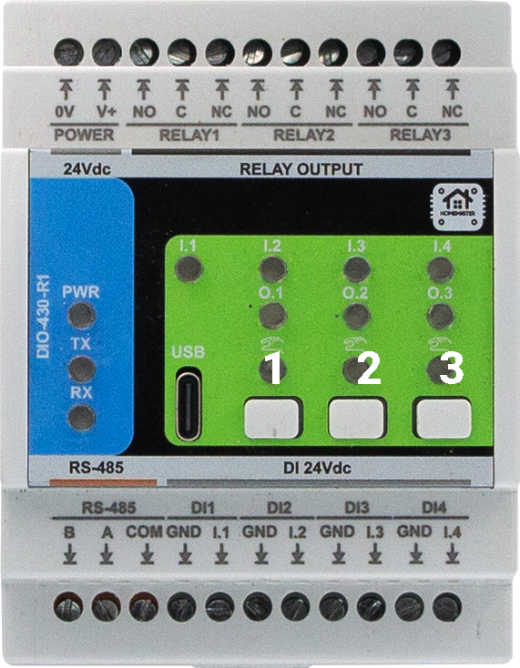
Combinations
- 2 + 3 → BOOT mode (enter bootloader for flashing)
- 1 + 3 → RESET (hardware reset/restart)
Steps (UF2/IDE)
- Connect USB‑C to a PC (disconnect RS‑485 during flashing).
- Hold Buttons 2 + 3 to enter BOOT. The board appears as a USB drive (UF2) or a serial device for IDE upload.
- Flash:
- UF2: drag‑and‑drop the new
.uf2file onto the mounted drive; the module restarts automatically. - PlatformIO / Arduino IDE: select the correct board/port and upload.
- UF2: drag‑and‑drop the new
- If needed, press Buttons 1 + 3 for a hardware RESET.
No factory‑reset function is provided. Configuration remains intact across normal firmware updates.
8.3 Arduino / PlatformIO Notes
Board / Toolchain
- Board: Generic RP2350 (or vendor core for RP2350A)
- USB: CDC enabled (serial logging)
- FS: LittleFS partition recommended (for settings)
Required Libraries (typical firmware)
ModbusSerial(or equivalent RTU)Arduino_JSONLittleFSSimpleWebSerial(or equivalent transport for WebConfig)Wire(I²C; if using expanders in forks)
Pin Mapping (DIO-430-R1 default firmware)
- Relays: R1=GPIO10, R2=GPIO9, R3=GPIO8 (active‑HIGH)
- Digital Inputs: IN1=GPIO6, IN2=GPIO11, IN3=GPIO12, IN4=GPIO7 (processed with enable/invert/debounce in firmware)
- Buttons: B1=GPIO1, B2=GPIO2, B3=GPIO3 (active‑LOW)
- User LEDs: L1=GPIO13, L2=GPIO14, L3=GPIO15 (active‑HIGH)
- RS‑485 (UART): TX=GPIO4, RX=GPIO5 (DE/RE handled in software)
Build Tips
- Start at 19200 8N1 on RS‑485 during bring‑up.
- After flashing, disconnect USB‑C and return control to the master on RS‑485.
8.4 Firmware Updates
- Method: USB‑C via UF2 drag‑drop or PlatformIO/Arduino upload.
- Config retention: Settings stored in flash/LittleFS are preserved unless explicitly erased.
- Recovery: If the app doesn’t start, use Buttons 2 + 3 to force BOOT, then re‑flash. Use Buttons 1 + 3 for a hardware RESET after flashing.
9. Maintenance & Troubleshooting
9.1 Status LEDs (typical)
- PWR — ON in normal operation
- TX/RX — blink on Modbus traffic
- User LEDs (1–3) — follow relay logic (Steady/Blink based on WebConfig mode)
9.2 Resets
- Power cycle: remove 24 V, wait 5 s, re‑apply
- Use Buttons 1 + 3 for a hardware RESET
9.3 Common Issues
| Symptom | Checks |
|---|---|
| No Modbus comms | A/B polarity, COM/GND reference, 120 Ω termination, address/baud match, only two end terminators |
| Relays don’t actuate | Relay Enabled in WebConfig, no active Override holding state, coil invert setting, Modbus coil writes acknowledged |
| DI not changing | Wire to INx/GNDx (isolated field side), check Enable/Invert/Action/Target in WebConfig, debounce expectations |
| USB won’t connect | Chrome/Edge with Web Serial, close other serial apps, check cable/port permissions |
| Config not saved | Allow idle for auto‑save or use Save if available; verify LittleFS space |
10. Open Source & Licensing
- Hardware: CERN‑OHL‑W v2
- Firmware: GPLv3
- Config Tools (WebConfig UI): MIT (unless folder states otherwise)
See the repository LICENSE files for the exact texts and sub‑component licenses.
11. Downloads
- Firmware binaries
- YAML configs (ESPHome)
- Package & examples:
DIO-430-R1/Firmware/default_dio_430_r1_plc/
- Package & examples:
- WebConfig tool (HTML/JS)
- Schematics (PDF)
- Field Board:
Schematics/DIO-430-R1-FieldBoard.pdf - MCU Board:
Schematics/DIO-430-R1-MCUBoard.pdf
- Field Board:
- Images & diagrams
- Datasheets
- Refer to the
Schematics/folder BOM notes for part numbers (e.g., ISO1212, MAX485, HF115F).
- Refer to the
12. Support
- Official Support Portal: https://www.home-master.eu/support
- WebConfig Tool: https://www.home-master.eu/configtool-dio-430-r1
- YouTube: https://youtube.com/@HomeMaster
- Hackster: https://hackster.io/homemaster
- Reddit: https://reddit.com/r/HomeMaster
- Instagram: https://instagram.com/home_master.eu
DIO-430-R1 — Module for Smart I/O Control
HOMEMASTER – Modular control. Custom logic.
1. Introduction
The DIO-430-R1 is a configurable smart digital I/O module designed for digital input monitoring and relay-based output control in building automation, lighting, HVAC, alarms, and general control systems.
It offers 4 opto-isolated digital inputs, 3 high-current SPDT relays, 3 user buttons, and 3 configurable user LEDs. All I/O channels are individually configurable, allowing flexible logic such as toggle, pulse, manual override, and alarm indication.
It connects via RS-485 (Modbus RTU) to a MicroPLC, MiniPLC, or any compatible controller, and can also integrate with Home Assistant (ESPHome) or SCADA/PLC systems.
Configuration and diagnostics are performed through a driverless Web Serial interface via USB-C, using the browser-based WebConfig Tool. The module supports both master-controlled and standalone local logic modes.
| Subsystem | Qty | Description |
|---|---|---|
| Digital Inputs | 4 | Opto-isolated, dry contact compatible, noise-protected |
| Relays | 3 | SPDT (NO/NC), 16 A rated, dry contacts |
| LEDs | 3 | Configurable: Steady or Blink modes, linked to relays |
| Buttons | 3 | User-configurable for override or reset |
| Modbus RTU | Yes | RS-485 interface (Configurable: Addr 1–255, 9600–115200 baud) |
| USB-C | Yes | WebConfig tool access via Web Serial (Chrome/Edge) |
| Power | 24 V DC | Fused input, reverse-polarity and surge protected |
| MCU | RP2350 | Dual-core, with QSPI flash, USB, UART, LittleFS |
| Protection | TVS, PTC | ESD, surge, and short-circuit protection on I/O and power |
System Role & Communication
The module communicates over the RS-485 Modbus RTU bus, using A/B differential lines and a shared COM/GND reference. It supports poll-based communication, where a master device reads input states and writes relay commands.
All configuration — including input-to-relay mapping, LED modes, and button logic — is stored persistently in internal flash via LittleFS and can be changed live through USB-C + WebConfig.
Factory default communication settings:
- Modbus Address:
3 - Baud Rate:
19200 - Parity:
None - Stop Bits:
1
The module’s logic (input→relay mapping, LED modes, button behavior) is stored persistently in internal flash via LittleFS, and settings can be changed live using USB-C + WebConfig.
2. DIO-430-R1 — Technical Specification
2.1 Diagrams & Pinouts
System overview, board callouts, and pin mapping:
2.2 I/O and Electrical Summary
| Interface | Qty | Description |
|---|---|---|
| Digital Inputs | 4 | Galvanically isolated (ISO1212 class). Supports dry contacts or 24 V signals. PTC + TVS per channel. |
| Relay Outputs | 3 | SPDT (NO/NC/COM), 16 A dry contacts. Use RC/MOV snubbers or interposing contactors for inductive/mains loads. |
| User LEDs | 3 | Configurable (Steady/Blink). Follow relay or logic status. |
| Buttons | 3 | Momentary. Configurable for relay override/toggle. |
| RS-485 (Modbus RTU) | 1 | A/B/COM terminals. Daisy-chain topology. 120 Ω termination at both ends. |
| USB-C | 1 | Web Serial setup, diagnostics, and firmware flashing (ESD-protected). |
| Power Input | 1 | 24 V DC SELV. Reverse-polarity + surge protected. |
Electrical Ratings
| Parameter | Min | Typ | Max | Unit | Notes |
|---|---|---|---|---|---|
| Supply Voltage | 22 | 24 | 28 | V DC | SELV/PELV input |
| Logic Consumption | – | 1.5 | 3.0 | W | Excludes relay loads |
| Digital Input Range | 0 | 24 | 30 | V DC | Isolated, noise-protected |
| Relay Contact Current | – | – | 16 | A | SPDT dry contacts |
| Relay Contact Voltage | – | – | 250 | V AC | or 30 V DC max |
| RS-485 Data Rate | – | 19.2 | 115.2 | kbps | Default 19200 8N1 |
| USB-C Voltage | 4.75 | 5.0 | 5.25 | V DC | Service only |
| Operating Temp. | 0 | – | 40 | °C | ≤ 95 % RH, non-condensing |
Power budgeting: logic + LEDs + up to 3 relay coils + sensor loads → add ≥ 30 % PSU headroom.
2.3 Connectors & Terminal Map
| Block | Pins | Function | Notes |
|---|---|---|---|
| POWER | 0V, V+ | 24 V DC input | Reverse/surge protected |
| RELAY 1-3 | NO, C, NC | SPDT contacts | Add RC/MOV for inductive loads |
| DI 1-4 | INx, GNDx | Isolated digital inputs | 24 V field or dry contact |
| RS-485 | B, A, COM | Modbus RTU bus | Terminate 120 Ω at ends |
| USB-C | D+, D−, VBUS, GND | Setup / Service port | Not for field powering |
2.4 Reliability & Protection
- Reverse-path diode + high-side MOSFET on 24 V input.
- Local PTC + TVS protection on field interfaces.
- Relay drivers opto-isolated; RC/MOV suppression recommended.
- RS-485 with TVS, series protection, and fail-safe biasing.
- USB-C ESD-protected; CC resistors per spec.
- Non-volatile flash with auto-save after configuration changes.
2.5 Functional Overview
- Modbus RTU slave (factory Addr 3, 19200 8N1; configurable 1–255, 9600–115200).
- Inputs → Relays: per-input Enable/Invert/Action (
None/Toggle/Pulse) and Target (R1–R3orAll). - Buttons: assignable to relay override (toggle).
- LEDs: configurable Steady/Blink following relay status.
- Setup via WebConfig: USB-C → Chrome/Edge; set comms and I/O mapping.
- Persistent config: stored in LittleFS and restored on boot.
2.6 Mechanical & Environmental
| Property | Specification |
|---|---|
| Mounting | DIN-rail EN 50022 (35 mm) |
| Enclosure | PC/ABS V-0, panel mount |
| Dimensions | 70 × 90.6 × 67.3 mm (W × H × D) |
| Terminals | Pluggable 5.08 mm, 26–12 AWG (≤ 2.5 mm²), 0.5–0.6 Nm |
| Ingress Protection | IP20 (panel interior) |
| Operating Temp | 0–40 °C, ≤ 95 % RH (non-condensing) |
2.7 Standards & Compliance
| Standard / Directive | Description |
|---|---|
| Ingress Rating | IP20 (panel-mount only) |
| Altitude | ≤ 2000 m |
| Environmental | RoHS / REACH compliant components |
3. Use Cases
The DIO‑430‑R1 supports both lighting and motor/pump control — making it ideal for mixed automation tasks in smart homes, greenhouses, HVAC, and industrial setups.
Below are 3 versatile examples combining both types of loads.
3.1 Staircase Light with Motion Sensor + Circulation Pump
Automatically turns ON a staircase light and a circulation pump when motion is detected.
Setup Instructions:
- Set IN1 to
Action = Pulse,Target = Relay 1(light). - Set IN2 to
Action = Pulse,Target = Relay 2(pump). - Enable Relay 1 for the staircase lighting.
- Enable Relay 2 for the circulation pump.
- Set LED 1 =
Blink, source =Relay 1. - Set LED 2 =
Steady, source =Relay 2.
3.2 Manual Light + Fan Override (Wall Panel)
Wall-mounted buttons allow users to toggle lights and exhaust fans independently.
Setup Instructions:
- Assign Button 1 →
Relay 1 override (toggle)→ Room Light - Assign Button 2 →
Relay 2 override (toggle)→ Ventilation Fan - Enable both Relay 1 and Relay 2.
- Set LED 1 and LED 2 to
Steady, following respective relays. - Optionally use Modbus Coils
200–201for remote control.
3.3 Greenhouse Light + Irrigation Pump Automation
Lights and irrigation are controlled via digital inputs or remotely from a PLC.
Setup Instructions:
- IN3 →
Toggle, Target =Relay 1→ Grow Light - IN4 →
Pulse, Target =Relay 2→ Irrigation Pump - Enable Relay 1 and Relay 2.
- Assign Button 3 to
Relay 2 override (toggle)for manual watering. - Set LED 1 =
Steady(light status), LED 2 =Blink(pump running).
4. Safety Information
These guidelines apply to the DIO-430-R1 I/O module. Ignoring them may result in equipment damage, system failure, or personal injury.
⚠️ SELV/PELV Domains Only
- The DIO-430-R1 operates entirely within SELV/PELV low-voltage domains (e.g., 24 V DC, RS-485, USB 5 V).
- Do not connect mains voltage to any terminal. Use interposing contactors/PSUs for mains loads.
- Respect isolation boundaries: never bridge logic GND with isolated field grounds (e.g., GND_ISO / FGND).
- Connect sensor returns only to the isolated field ground; connect RS-485 COM/GND only within the same SELV domain.
4.1 General Requirements
| Requirement | Detail |
|---|---|
| Qualified Personnel | Installation and servicing must be done by qualified personnel familiar with 24 V control systems and RS-485. |
| Power Isolation | Disconnect the 24 V DC input before wiring. Lockout/tagout where applicable. |
| Environmental Limits | Mount in a clean, sealed enclosure; avoid condensation, conductive dust, or vibration. |
| Grounding | Bond the panel to PE. Keep RS-485 COM/GND shared with the controller side. |
| Voltage Compliance | SELV only on all terminals. Follow relay contact ratings on the product label/datasheet. Use upstream fusing and surge protection. |
4.2 Installation Practices
| Task | Guidance |
|---|---|
| ESD Protection | Handle by the enclosure/edge only. Use an antistatic wrist strap when the board is exposed. |
| DIN Rail Mounting | Mount securely on 35 mm DIN rail inside an IP-rated cabinet. Leave cable slack for strain relief. |
| Wiring | Use correct wire gauge and torque terminal screws. Separate power, DI, relay, and RS-485 harnesses. |
| Isolation Domains | Respect isolation: do not bridge logic GND to isolated field grounds (e.g., GND_ISO/FGND). Keep analog/sensor returns on the isolated side. |
| Commissioning | Before power-up, verify polarity, relay NO/NC routing, RS-485 A/B orientation and termination. |
4.3 I/O & Interface Warnings
🔌 Power
| Area | Warning |
|---|---|
| 24 V DC Input | Use a clean, fused SELV supply. Reverse-polarity protection exists but may disable the module when triggered. |
| Sensor Rail | Power sensors from a SELV rail. Observe polarity. Fuse external branches as required. |
| Surge/Noise | In noisy panels, add upstream surge/EMI suppression and keep high-current wiring away from control wiring. |
⏽ Inputs (Digital)
| Area | Warning |
|---|---|
| Type | Dry contact / 24 V signaling only, per your standard. Do not inject mains or undefined levels. |
| Isolation | Inputs are isolated from logic. Keep sensor returns on the field/isolated domain; do not bond to logic GND. |
| Debounce | Firmware provides debounce, but route away from contactors/VFDs and use shielded/twisted pairs for long runs. |
| Polarity | Configure invert/action in WebConfig; verify state transitions after wiring. |
⚙️ Relays (Outputs)
| Area | Warning |
|---|---|
| Contact Type | SPDT (NO/NC/COM) dry contacts. Follow the contact rating on the device label/datasheet. |
| Inductive Loads | For motors/solenoids/contactors, add an RC snubber or MOV at the load. Consider interposing relays/ contactors for higher power. |
| Separation | Keep relay load wiring physically separate from signal wiring. De-energize before servicing. |
| Verification | After wiring, verify NO/NC behavior and load polarity before enabling automation. |
🖧 RS-485 (Modbus RTU)
| Area | Warning |
|---|---|
| Topology | Use twisted pair; daisy-chain (no stubs). Terminate with 120 Ω at both physical ends. |
| Polarity | Maintain A/B polarity consistently. Share COM/GND reference between nodes (same SELV domain). |
| EMC | Route away from VFDs, contactors, and mains bundles. Use shielded cable in high-EMI environments. |
| Protection | Port includes protection, but good wiring practice is still required to avoid transients. |
🔌 USB-C (Front / Setup)
| Area | Warning |
|---|---|
| Purpose | Setup & maintenance only (WebConfig / firmware). Not intended for powering field devices. |
| ESD/EMI | Avoid hot-plugging in high-EMI areas. Use a grounded service laptop. Disconnect after commissioning. |
🔆 Front Panel (Buttons & LEDs)
| Area | Warning |
|---|---|
| Buttons & LEDs | Buttons can override relays; document operating procedures. Lock out overrides for safety-critical installs. |
🛡️ Shielding & EMC
| Area | Recommendation |
|---|---|
| Cable Shields | Terminate shields at one end (typically the PLC/controller). Keep runs short and away from high-voltage/EMI sources. |
✅ Pre-Power Checklist
- No bridge between logic GND and isolated GND_ISO/FGND
- A/B polarity and 120 Ω termination confirmed at bus ends
- not exceed the contact rating; snubbers added for inductive loads
- dry contact/SELV only; sensor polarity and returns verified
5. Installation & Quick Start
The DIO-430-R1 joins your system over RS-485 (Modbus RTU). Setup has two parts:
- Physical wiring, 2) Digital configuration (WebConfig → optional PLC/ESPHome).
5.1 What You Need
| Category | Item / Notes |
|---|---|
| Hardware | DIO-430-R1 — DIN-rail module with 4× DI, 3× SPDT relays, 3× buttons, 3× LEDs, USB-C, RS-485. |
| Controller (master) | HomeMaster MiniPLC/MicroPLC or any Modbus RTU master. |
| 24 VDC PSU (SELV) | Regulated 24 VDC; size for logic + relay coils + sensors; inline panel fuse/breaker. Power input stage includes fuse/TVS/reverse-polarity protection. |
| RS-485 cable | Twisted pair for A/B + COM/GND reference, 120 Ω termination at both ends of the trunk. |
| USB-C cable | For WebConfig via a Chromium browser (service/commissioning). |
| Software | Chromium-based browser with Web Serial (Chrome/Edge). Web page exposes Address/Baud + I/O mapping. |
| Field I/O | Dry contacts to DI1…DI4 (isolated front-end per channel). Relays (NO/NC/COM) drive LV loads or interposing contactors; add RC/MOV snubbers for inductive loads. |
Quick path: mount → wire 24 VDC + RS-485 A/B/COM → connect USB-C → WebConfig: set Address/Baud + map inputs → relays/LEDs → disconnect USB → hand over to controller.
5.2 Power
The module uses 24 VDC primary. Onboard regulation provides 5 V → 3.3 V for logic; DI front-end is isolated.
5.2.1 Supply Types
- 24 VDC DIN-rail PSU → 24Vdc(+) / 0V(–) power terminals (top row: POWER).
- Sensor side (DI) — isolated input receivers accept field signals; feed your sensors from the 24 V field rail and return to the DI GND pins (per-channel). Do not back-power logic from sensor rails.
5.2.2 Sizing (rule of thumb)
Account for:
- Base electronics + LEDs
- Relay coils (up to 3 simultaneously)
- Sensor rails (DI field side, if powered from the same 24 V source)
Size PSU for worst-case relays + sensors, then add ≥30 % headroom.
5.2.3 Power Safety
- Correct polarity; keep logic GND and DI field ground separate (respect isolation domains).
- Keep upstream fusing/breaker in place; the board also has input fuse/TVS/reverse-polarity MOSFET.
- Use snubbers on inductive loads; prefer interposing contactors for motors/pumps.
- De-energize before wiring; check shorts before power-up.
5.3 Networking & Communication
Runtime control is via RS-485 (Modbus RTU). USB-C is for local setup/diagnostics (Web Serial).
5.3.1 RS-485 (Modbus RTU)
Physical
- Terminals (lower front row): B, A, COM/GND → then DI and DI-GNDs. Maintain A/B polarity, share the COM/GND reference with the controller.
- Cable: Twisted pair (preferably shielded) for A/B + reference.
- Termination: 120 Ω at both physical ends of the trunk; avoid stubs.
Protocol
- Role: RTU slave; controller is master.
- Address: 1–255. Factory default: Address 3, 19200 8N1.
- Required: Dedicated 24 VDC power (bus is data-only).
Checklist
- A→A, B→B, COM→COM (GND ref).
- Two end terminations only; daisy-chain topology.
- Consistent A/B polarity end-to-end.
5.3.2 USB-C (WebConfig)
Purpose: Chromium (Chrome/Edge) Web Serial setup/diagnostics page.
Steps
- Connect USB-C to the module.
- Open the DIO-430-R1 WebConfig page and click Connect.
- Set Modbus Address & Baud (header shows Active Modbus Configuration).
- Configure Inputs / Relays / LEDs / Buttons; changes apply live and are saved to flash.
- Use Reset Device from the page if needed (dialog confirms).
If Connect is disabled: ensure Chromium + serial permission; close other apps that might hold the port.
5.4 Installation & Wiring
This section shows typical wiring for power, inputs, relays, RS-485, and the USB-C service port.
⚠️ Work on de-energized equipment only. Use SELV/PELV supplies for logic and field inputs. Mains on relay contacts must be wired by qualified personnel.
A) Power — 24 VDC (SELV)
Wire the regulated 24 VDC supply to the top POWER terminals: V+ and 0V.
Notes
- Keep V+/0V as a twisted pair; route away from motor cables/contactors.
- The module includes input protection (fuse/TVS/reverse-polarity MOSFET).
B) Digital Inputs (DI1…DI4)
Each input is isolated. Land the contact/sensor on INx with the paired GNDx return.
Tips
- Supports dry contacts or compatible 24 V field signals.
- Configure in WebConfig: Enabled/Invert, Action (
None / Toggle / Pulse), Control target (None / All / R1 / R2 / R3). - Keep field wiring shielded/twisted for long runs; terminate shield at one end only.
C) Relay Outputs (R1…R3)
Relays provide dry SPDT contacts (NO/NC/COM) for switching low-voltage loads or driving an interposing contactor for mains/inductive loads.
Best practices
- Add RC/MOV snubbers across inductive loads (fans, pumps, contactors).
- Keep load and logic wiring separated; observe conductor ratings and local code.
D) Sensor Rails (12 V / 5 V)
This module does not export auxiliary 12 V/5 V rails for field devices.
- Power sensors from your panel 24 V rail (or external rails as required).
- Return sensor commons to the matching DI GNDx terminals; do not bond field ground to logic GND.
E) RS-485 (Modbus RTU)
The lower left terminals expose B, A, and COM (GND). Use shielded twisted pair and daisy-chain topology.
Checklist
- Wire A→A, B→B, and share COM/GND with the controller.
- Terminate the two physical bus ends with 120 Ω.
- Default protocol: Address 3, 19200 8N1 (change via WebConfig).
F) USB-C (Service / WebConfig)
- Use USB-C for commissioning and diagnostics only (Web Serial in Chrome/Edge).
- Not for powering field devices. Disconnect after setup and hand control to the RS-485 master.
5.5 Software & UI Configuration
Use the WebConfig page (USB-C + Chrome/Edge) to set Modbus comms and map I/O. Changes apply immediately and are saved to flash.
Screens shown below are from the DIO-430-R1 WebConfig.
A) WebConfig setup (Address & Baud)
- Connect the module via USB-C → open the WebConfig page → click Connect.
- In Modbus Address, choose 1–255 (factory default 3).
- In Baud Rate, select 9600–115200 (factory default 19200 8N1).
- Confirm the Active Modbus Configuration banner updates (Address/Baud).
Default values (Addr 3, 19200 8N1) are also noted in the module docs.
B) Inputs — enable / invert / group (control target)
Each IN1…IN4 card provides:
- Enabled: include the input in logic.
- Inverted: logical inversion.
- Action:
None / Toggle / Pulse. - Control target:
None / Control all / Relay 1 / Relay 2 / Relay 3.
This matches the firmware’s input options and allows direct mapping from inputs to one or more relays without a PLC.
Tips
- Use Toggle to latch a relay on each press; Pulse for momentary actions (timers handled by controller if needed).
- For “group” behavior, select Control all to operate Relays 1–3 together.
C) Relays — logic mode (group/manual)
For Relay 1–3:
- Enabled: relay is controllable.
- Inverted: invert drive polarity (use only if required by wiring).
Logic modes in practice
- Group control: Achieve via Input Control target = Control all (see Inputs section).
- Manual / local override: Assign Buttons (below) to toggle a specific relay even when the PLC also controls it.
D) LED and Button mapping
Buttons (3)
- Action: choose
Noneor Relay override (toggle) for Relay 1/2/3. This provides local/manual control without a PLC.
User LEDs (3)
- Mode:
SteadyorBlink(active when source is ON). - Activate when: select the source relay to follow (e.g., LED1 foll
5.6 Getting Started (3 Phases)
Phase 1 — Wire
- 24 VDC to V+ / 0V (GND) (top POWER terminals)
Use a regulated SELV supply; keep pairs twisted. - Digital inputs (IN1–IN4): dry contacts → INx / GNDx
Respect isolation domains; do not bridge logic GND ↔ field GND. - Relay outputs (R1–R3): COM / NO / NC
Prefer interposing contactors for motors/pumps; add RC/MOV snubber on inductive loads. - RS-485: A / B / COM (GND)
Shielded twisted pair; daisy-chain; terminate bus ends with 120 Ω. - USB-C (service): for WebConfig only (no field powering).
👉 See: Installation & Quick Start
Phase 2 — Configure (WebConfig)
- Open
https://www.home-master.eu/configtool-dio-430-r1in Chrome/Edge. - Connect USB-C → Select port → Connect.
- Set:
- Modbus Address / Baud (default: Addr 3, 19200 8N1)
- Inputs: Enable / Invert / Action (
None / Toggle / Pulse) / Control target (None / All / R1 / R2 / R3) - Relays: Enable (optional Invert)
- Buttons: map to Relay override (toggle) (R1/R2/R3)
- User LEDs: Mode (
Steady / Blink) + Activate when (follow a relay)
- Click Reset Device if prompted; settings auto-save to flash.
👉 See: WebConfig UI
Phase 3 — Integrate (Controller)
- Connect controller (MiniPLC/MicroPLC/PLC/SCADA/ESPHome) via RS-485.
- Match address and baud.
- Poll:
- Discrete inputs for DI states and relay states (per your mapping)
- Write:
- Coils to control relays (e.g., R1/R2/R3 ON/OFF)
- Use with:
- HomeMaster MicroPLC / MiniPLC
- ESPHome / SCADA / PLC
👉 See: Modbus RTU Communication & Integration Guide
✅ Verify
| Area | What to Check |
|---|---|
| LEDs | PWR = ON; TX/RX blink during RS-485 traffic |
| Inputs | Toggling a wall switch/sensor changes INx state in WebConfig/Modbus |
| Relays | Coil writes toggle R1–R3; loads switch correctly; snubber installed for inductive loads |
| Address/Baud | Controller reads module at the configured address/baud without errors |
| Isolation | No unintended bond between logic GND and DI field GNDx |
6. Modbus RTU Communication
Role: RTU slave (controller is master)
Defaults: Address 3, 19200 8N1 (change in WebConfig → Modbus)
Addressing shown below uses zero-based offsets (e.g., Holding Reg
40000= offset0).
If your master uses 1-based display (e.g., 40001), add +1 to the register number.
6.1 Address Range & Map (Overview)
| Type | Range (offsets) | Purpose |
|---|---|---|
| Coils (0x) | 00000…00031 |
Relay commands, device control |
| Discrete Inputs (1x) | 10000…10031 |
DI states, relay echo states |
| Input Registers (3x) | 30000…30031 |
Read-only status (masks, counters) |
| Holding Registers (4x) | 40000…40063 |
Config & runtime parameters (DI actions/targets, relay/LED/button settings, comms) |
6.2 Coils (0x) — Commands
| Coil | Name | Description |
|---|---|---|
00000 |
R1_CMD | Relay 1 ON/OFF (write 1/0) |
00001 |
R2_CMD | Relay 2 ON/OFF |
00002 |
R3_CMD | Relay 3 ON/OFF |
00010 |
SAVE_CFG | Persist current settings to flash (write 1) |
00011 |
RESET | Soft reset device (write 1) |
Coils drive relays regardless of input mappings (local buttons still work as overrides).
6.3 Discrete Inputs (1x) — States
| DI | Name | Description |
|---|---|---|
10000 |
DI1_STATE | Digital Input 1 (after invert option) |
10001 |
DI2_STATE | Digital Input 2 |
10002 |
DI3_STATE | Digital Input 3 |
10003 |
DI4_STATE | Digital Input 4 |
10010 |
R1_STATE | Relay 1 actual state (echo) |
10011 |
R2_STATE | Relay 2 actual state |
10012 |
R3_STATE | Relay 3 actual state |
6.4 Holding Registers (4x) — Configuration & Runtime
6.4.1 Identity / Comms
| Reg | Name | R/W | Encoding | Notes |
|---|---|---|---|---|
40000 |
MODEL_ID | R | u16 | e.g., 0x0430 (DIO-430) |
40001 |
FW_BUILD | R | YYYYMM | Snapshot / build tag |
40002 |
MB_ADDR | R/W | u16 | 1…255 |
40003 |
MB_BAUD | R/W | enum | 0=9600,1=19200,2=38400,3=57600,4=115200 |
40004 |
MB_PARITY | R/W | enum | 0=None,1=Even,2=Odd (default 0) |
6.4.2 Digital Inputs (per-channel)
Action codes: 0=None, 1=Toggle (latched), 2=Pulse (momentary)
Target codes: 4=None, 0=Control all, 1=R1, 2=R2, 3=R3
| Reg | Name | R/W | Encoding | Notes |
|---|---|---|---|---|
40010 |
DI_EN_MASK | R/W | bitmask | bit0…3 → IN1…IN4 enable |
40011 |
DI_INV_MASK | R/W | bitmask | bit0…3 → IN1…IN4 invert |
40012 |
DI1_ACTION | R/W | u16 enum | 0/1/2 |
40013 |
DI2_ACTION | R/W | u16 enum | 0/1/2 |
40014 |
DI3_ACTION | R/W | u16 enum | 0/1/2 |
40015 |
DI4_ACTION | R/W | u16 enum | 0/1/2 |
40016 |
DI1_TARGET | R/W | u16 enum | 4/0/1/2/3 |
40017 |
DI2_TARGET | R/W | u16 enum | 4/0/1/2/3 |
40018 |
DI3_TARGET | R/W | u16 enum | 4/0/1/2/3 |
40019 |
DI4_TARGET | R/W | u16 enum | 4/0/1/2/3 |
6.4.3 Relays / Buttons / LEDs
| Reg | Name | R/W | Encoding | Notes |
|---|---|---|---|---|
40020 |
RLY_EN_MASK | R/W | bitmask | bit0…2 → R1…R3 enable |
40021 |
RLY_INV_MASK | R/W | bitmask | invert coil logic (rarely used) |
40022 |
BTN1_ACTION | R/W | u16 enum | 0=None, 5=R1 toggle, 6=R2 toggle, 7=R3 toggle |
40023 |
BTN2_ACTION | R/W | u16 enum | as above |
40024 |
BTN3_ACTION | R/W | u16 enum | as above |
40025 |
LED_MODE | R/W | bit-packed | bits0…1 = LED1 (0=Steady,1=Blink), bits2…3 = LED2, bits4…5 = LED3 |
6.4.4 Status / Diagnostics
| Reg | Name | R/W | Encoding | Notes |
|---|---|---|---|---|
40030 |
UPTIME_S_LO | R | u16 | lower 16 bits |
40031 |
UPTIME_S_HI | R | u16 | upper 16 bits (32-bit seconds) |
40032 |
ERR_CODE | R | u16 | 0=OK; non-zero = last error |
40033 |
FLAGS | R | bitmask | e.g., cfg-dirty, wd-reset (implementation-specific) |
Note: All configuration is usually done via WebConfig. The registers above are provided to enable controller-side provisioning and telemetry when needed.
6.5 Input Registers (3x) — Convenience (Read-only)
| Reg | Name | Encoding | Description |
|---|---|---|---|
30000 |
DI_STATE_MASK | bitmask | bit0…3 → IN1…IN4 (post-invert) |
30001 |
RLY_STATE_MASK | bitmask | bit0…2 → R1…R3 |
30002 |
BTN_STATE_MASK | bitmask | bit0…2 → B1…B3 (momentary) |
30003 |
LED_STATE_MASK | bitmask | bit0…2 → LED1…LED3 active |
6.6 Register Use Examples
A) Toggle a relay from a PLC
- Write
1to Coil00001(R2_CMD) → Relay 2 ON - Write
0to the same coil → Relay 2 OFF
B) Map IN3 to drive Relay 1 as a latched toggle
40010 (DI_EN_MASK)→ set bit2 = 1 (enable IN3)40011 (DI_INV_MASK)→ set bit2 = 0 (no invert)40014 (DI3_ACTION)→ write1(Toggle)40018 (DI3_TARGET)→ write1(R1)
C) Set Button 2 to local override of Relay 2
40023 (BTN2_ACTION)→ write6(R2 toggle)
D) Make LED1 blink when Relay 1 is active
- In
40025 (LED_MODE): set LED1 field to Blink (value1)
E) Change Modbus address & baud from the master
40002 (MB_ADDR)→ new address (1…255)40003 (MB_BAUD)→ new enum (e.g.,1for 19200)- Coil
00010 (SAVE_CFG)= 1, then00011 (RESET)= 1
6.7 Polling Recommendations
- Transport: RS-485, daisy-chain, 120 Ω terminators at both ends, share COM/GND reference.
- Rates:
- States (1x/3x): 5–10 Hz typical (100–200 ms) for DI/relay/LED masks.
- Coils (0x): write only on change; read-after-write or echo via
RLY_STATE_MASK. - Holding (4x): configure at commissioning; read occasionally (e.g., every 5–10 s).
- Framing: Prefer 19200 8N1 for mixed networks; increase only on short, low-noise trunks.
- Time-outs/Retries: 100–250 ms timeout, 2–3 retries; back-off on bus errors.
- Edge logic: If a PLC supervises latching/timers, set DI Action = Pulse; if you want module-local latching, set Action = Toggle.
7. ESPHome Integration Guide (MiniPLC/MicroPLC + DIO-430-R1)
Support status: ✔️ Supported via ESPHome
uart+modbus+modbus_controllerand a reusable package.
Module role: Modbus RTU slave on RS-485.
Defaults: Address 3, 19200 8N1 (change in WebConfig).
7.1 Minimal YAML (Controller side)
Use this on the MiniPLC/MicroPLC (ESPHome). It enables the RS-485 bus and imports a ready-made DIO package.
uart:
  id: uart_modbus
  tx_pin: 17
  rx_pin: 16
  baud_rate: 19200
  parity: NONE
  stop_bits: 1

modbus:
  id: modbus_bus
  uart_id: uart_modbus

packages:
  dio1:
    url: https://github.com/isystemsautomation/HOMEMASTER
    ref: main
    files:
      - path: DIO-430-R1/Firmware/default_dio_430_r1_plc/default_dio_430_r1_plc.yaml
        vars:
          dio_prefix: "DIO#1"  # shown in Home Assistant entity names
          dio_id: dio_1        # internal unique id
          dio_address: 4       # Modbus address set in WebConfig for this DIO
    refresh: 1d
For multiple DIOs, duplicate the
dio1:block (dio2:,dio3:…) with uniquedio_id,dio_prefix, anddio_address.
7.2 Entities exposed (from the package)
- Binary Sensors
- DI1…DI4 (post-invert, debounced)
- Switches
- Relay 1–3 (Modbus coils ON/OFF)
- Override ON/OFF for Relay 1–3 (forces state until released)
- Save Config / Soft Reset (commissioning helpers)
- Sensors (diagnostic)
- Button state mask (optional)
- LED state mask (optional)
- Uptime / flags (optional)
- Select/Number (optional, commissioning)
- Modbus address/baud view
- Per-input Enable/Invert/Action/Target (read/write helpers if enabled in the package)
The package sticks to the Modbus map defined in Section 6 (coils for relays, discrete inputs for DI states, holding/input registers for masks and configuration).
7.3 Optional: direct (manual) entity mapping
If you prefer not to use the package, you can expose the core points directly:
modbus_controller:
  - id: dio430_4
    address: 4
    modbus_id: modbus_bus
    update_interval: 200ms
    command_throttle: 100ms

binary_sensor:
  # DI1..DI4 as Discrete Inputs (1x offsets 0..3)
  - platform: modbus_controller
    modbus_controller_id: dio430_4
    name: "DIO#1 DI1"
    register_type: discrete_input
    address: 0
  - platform: modbus_controller
    modbus_controller_id: dio430_4
    name: "DIO#1 DI2"
    register_type: discrete_input
    address: 1
  - platform: modbus_controller
    modbus_controller_id: dio430_4
    name: "DIO#1 DI3"
    register_type: discrete_input
    address: 2
  - platform: modbus_controller
    modbus_controller_id: dio430_4
    name: "DIO#1 DI4"
    register_type: discrete_input
    address: 3

switch:
  # Relays as Coils (0x offsets 0..2)
  - platform: modbus_controller
    modbus_controller_id: dio430_4
    name: "DIO#1 Relay 1"
    register_type: coil
    address: 0
  - platform: modbus_controller
    modbus_controller_id: dio430_4
    name: "DIO#1 Relay 2"
    register_type: coil
    address: 1
  - platform: modbus_controller
    modbus_controller_id: dio430_4
    name: "DIO#1 Relay 3"
    register_type: coil
    address: 2

sensor:
  # (Optional) LED and Button masks from Input Registers 30003/30002
  - platform: modbus_controller
    modbus_controller_id: dio430_4
    name: "DIO#1 LED Mask"
    register_type: input
    address: 3
    value_type: U_WORD
    accuracy_decimals: 0
  - platform: modbus_controller
    modbus_controller_id: dio430_4
    name: "DIO#1 Button Mask"
    register_type: input
    address: 2
    value_type: U_WORD
    accuracy_decimals: 0
7.4 Home Assistant tips (dashboards & automations)
- Dashboards
- Lighting panel: Card for Relay 1–3 plus DI tiles (e.g., wall switch/sensor feedback).
- Maintenance card: Override ON/OFF for each relay + Reset Device + Save Config.
- Automations
- DI → Relay: If you keep the logic in HA/PLC (instead of module mapping), trigger relay switches when a DI goes high.
- Night mode: When
input_boolean.night_modeis on, force a specific Override ON and release it in the morning.
- Naming
- Use
dio_prefixto keep entities readable (DIO#1 Relay 1,DIO#2 DI3, etc.).
- Use
7.5 Troubleshooting
- No response / timeouts: check A/B polarity, shared COM/GND reference, and 120 Ω termination at bus ends.
- Wrong device: make sure
dio_addressin the package matches the WebConfig address. - Relays don’t switch: ensure the relay is Enabled in WebConfig and not “held” by an Override.
- DI not changing: verify wiring to INx/GNDx (respect isolation); check Invert/Enable/Action/Target in WebConfig.
7.7 Notes & Versions
- Works with recent ESPHome releases (e.g., 2025.x).
- Keep
update_intervalmodest (e.g., 200–500 ms) unless you need faster DI polling. - For multiple devices on one bus, stagger
update_interval/command_throttleto reduce collisions.
8. Programming & Customization (DIO-430-R1)
8.1 Supported Languages
- Arduino
- C++ (PlatformIO)
- MicroPython (community builds for RP23xx-class MCUs)
8.2 Flashing (USB‑C, Hardware Buttons Only)
The module exposes a USB device for flashing. All reset/boot actions are done with the front buttons in hardware.
Button layout (front panel):
Combinations
- 2 + 3 → BOOT mode (enter bootloader for flashing)
- 1 + 3 → RESET (hardware reset/restart)
Steps (UF2/IDE)
- Connect USB‑C to a PC (disconnect RS‑485 during flashing).
- Hold Buttons 2 + 3 to enter BOOT. The board appears as a USB drive (UF2) or a serial device for IDE upload.
- Flash:
- UF2: drag‑and‑drop the new
.uf2file onto the mounted drive; the module restarts automatically. - PlatformIO / Arduino IDE: select the correct board/port and upload.
- UF2: drag‑and‑drop the new
- If needed, press Buttons 1 + 3 for a hardware RESET.
No factory‑reset function is provided. Configuration remains intact across normal firmware updates.
8.3 Arduino / PlatformIO Notes
Board / Toolchain
- Board: Generic RP2350 (or vendor core for RP2350A)
- USB: CDC enabled (serial logging)
- FS: LittleFS partition recommended (for settings)
Required Libraries (typical firmware)
ModbusSerial(or equivalent RTU)Arduino_JSONLittleFSSimpleWebSerial(or equivalent transport for WebConfig)Wire(I²C; if using expanders in forks)
Pin Mapping (DIO-430-R1 default firmware)
- Relays: R1=GPIO10, R2=GPIO9, R3=GPIO8 (active‑HIGH)
- Digital Inputs: IN1=GPIO6, IN2=GPIO11, IN3=GPIO12, IN4=GPIO7 (processed with enable/invert/debounce in firmware)
- Buttons: B1=GPIO1, B2=GPIO2, B3=GPIO3 (active‑LOW)
- User LEDs: L1=GPIO13, L2=GPIO14, L3=GPIO15 (active‑HIGH)
- RS‑485 (UART): TX=GPIO4, RX=GPIO5 (DE/RE handled in software)
Build Tips
- Start at 19200 8N1 on RS‑485 during bring‑up.
- After flashing, disconnect USB‑C and return control to the master on RS‑485.
8.4 Firmware Updates
- Method: USB‑C via UF2 drag‑drop or PlatformIO/Arduino upload.
- Config retention: Settings stored in flash/LittleFS are preserved unless explicitly erased.
- Recovery: If the app doesn’t start, use Buttons 2 + 3 to force BOOT, then re‑flash. Use Buttons 1 + 3 for a hardware RESET after flashing.
9. Maintenance & Troubleshooting
9.1 Status LEDs (typical)
- PWR — ON in normal operation
- TX/RX — blink on Modbus traffic
- User LEDs (1–3) — follow relay logic (Steady/Blink based on WebConfig mode)
9.2 Resets
- Power cycle: remove 24 V, wait 5 s, re‑apply
- Use Buttons 1 + 3 for a hardware RESET
9.3 Common Issues
| Symptom | Checks |
|---|---|
| No Modbus comms | A/B polarity, COM/GND reference, 120 Ω termination, address/baud match, only two end terminators |
| Relays don’t actuate | Relay Enabled in WebConfig, no active Override holding state, coil invert setting, Modbus coil writes acknowledged |
| DI not changing | Wire to INx/GNDx (isolated field side), check Enable/Invert/Action/Target in WebConfig, debounce expectations |
| USB won’t connect | Chrome/Edge with Web Serial, close other serial apps, check cable/port permissions |
| Config not saved | Allow idle for auto‑save or use Save if available; verify LittleFS space |
10. Open Source & Licensing
- Hardware: CERN‑OHL‑W v2
- Firmware: GPLv3
- Config Tools (WebConfig UI): MIT (unless folder states otherwise)
See the repository LICENSE files for the exact texts and sub‑component licenses.
11. Downloads
- Firmware binaries
- YAML configs (ESPHome)
- Package & examples:
DIO-430-R1/Firmware/default_dio_430_r1_plc/
- Package & examples:
- WebConfig tool (HTML/JS)
- Schematics (PDF)
- Field Board:
Schematics/DIO-430-R1-FieldBoard.pdf - MCU Board:
Schematics/DIO-430-R1-MCUBoard.pdf
- Field Board:
- Images & diagrams
- Datasheets
- Refer to the
Schematics/folder BOM notes for part numbers (e.g., ISO1212, MAX485, HF115F).
- Refer to the
12. Support
- Official Support Portal: https://www.home-master.eu/support
- WebConfig Tool: https://www.home-master.eu/configtool-dio-430-r1
- YouTube: https://youtube.com/@HomeMaster
- Hackster: https://hackster.io/homemaster
- Reddit: https://reddit.com/r/HomeMaster
- Instagram: https://instagram.com/home_master.eu