
Overview
The RGB-621-R1 is a configurable smart RGB+CCT LED controller designed for architectural lighting, home automation, ambient lighting, and industrial control. With 5 high-current PWM outputs for RGB and Tunable White LED control, 2 isolated digital inputs, and 1 relay output, it offers professional lighting control and seamless integration via Modbus RTU (RS-485). Ideal for smart homes, commercial lighting, and automation systems.
Getting Started
Quick Setup Process
Mount & Wire – Install on 35mm DIN rail, connect 24V DC power, sensors, and relay loads.
Configure – Plug in USB-C, open the WebConfig tool in Chrome/Edge, set Modbus address and I/O mapping.
Integrate – Connect to your controller via RS-485 and start automation.
What You Need
RGB-621-R1 module
24V DC SELV power supply
24/12V DC SELV LED strip power supply
RS-485 cable (twisted pair)
USB-C cable for configuration
24/12V RGB+CCT LED strips
Chromium-based browser (Chrome/Edge)
Web Configuration Steps
Connect USB-C to module and PC
Click "Connect" and select serial port
Set Modbus address (default: 3) and baud rate (default: 19200 8N1)
Configure input actions, relay mapping, LED modes, and button functions
Settings save automatically to flash
Tech Specs
Technical Specifications | etails |
|---|---|
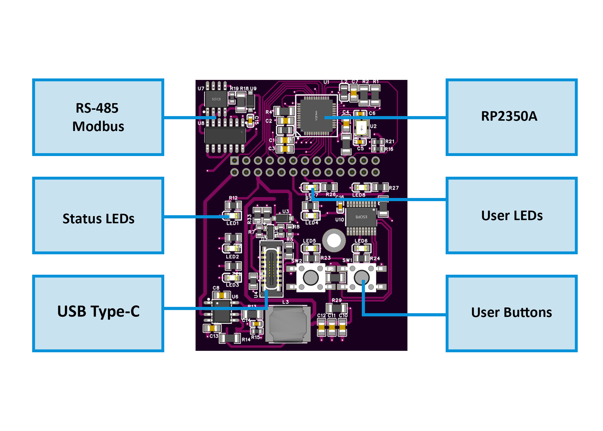
| Microcontroller | RP2350A, Dual-core ARM Cortex-M33 @ 133MHz |
| Input Voltage | 24V DC SELV/PELV |
LED Input Voltage | 24/12V DC SELV/PELV |
| PWM Outputs | 5 channels (R, G, B, CW, WW) |
| PWM Current | 5A per channel (25A max total) |
| Digital Inputs | 2 isolated channels |
| Relay Output | SPST-NO, 16A @ 250VAC/30VDC |
| Communication | RS-485 (Modbus RTU) |
| Flash Memory | 32 Mbit QSPI Flash |
| Isolation | 3 kVrms (inputs ↔ logic) |
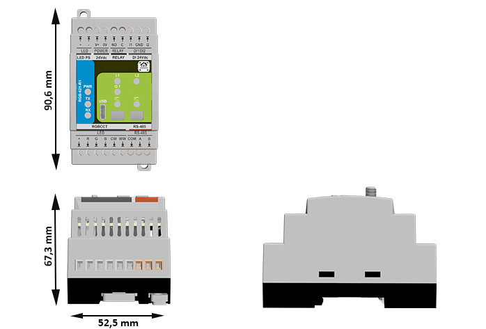
| Dimensions | 52.5 × 90.6 × 67.3 mm |
| Mounting | 35mm DIN rail (EN 50022) |
| Operating Temp | 0°C to 40°C |
| Weight | ~0.25 kg |
Documentation
The DIO-430-R1 is open-source hardware! You can build your own board using the following files:
Hardware Design Files
MCU Board Schematic: RGB-621-R1-MCUBoard.pdf
Field Board Schematic: RGB-621-R1-FieldBoard.pdf
System Block Diagram: RGB_DiagramBlock.png
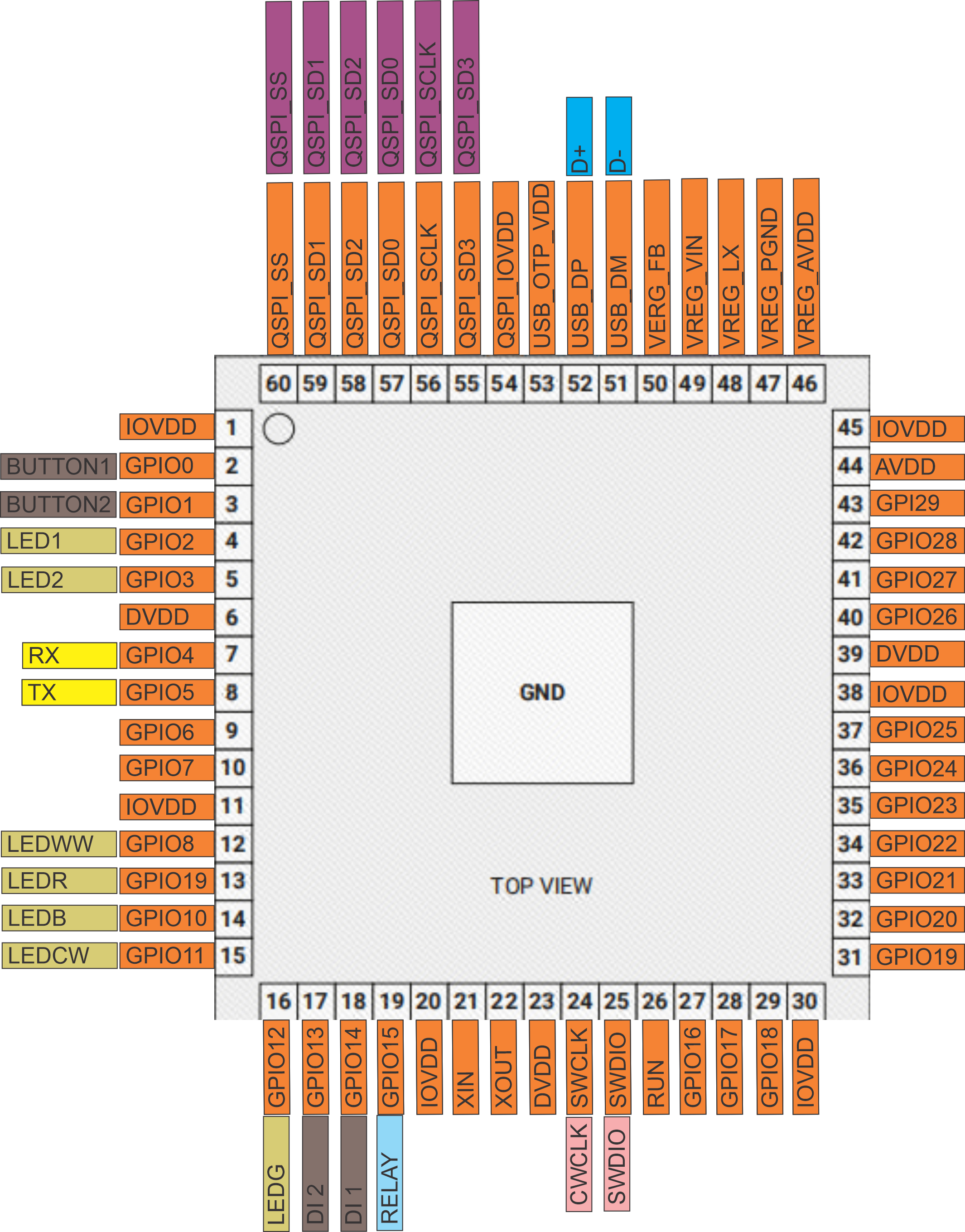
MCU Pinout Diagram: RGB_MCU_Pinouts.png
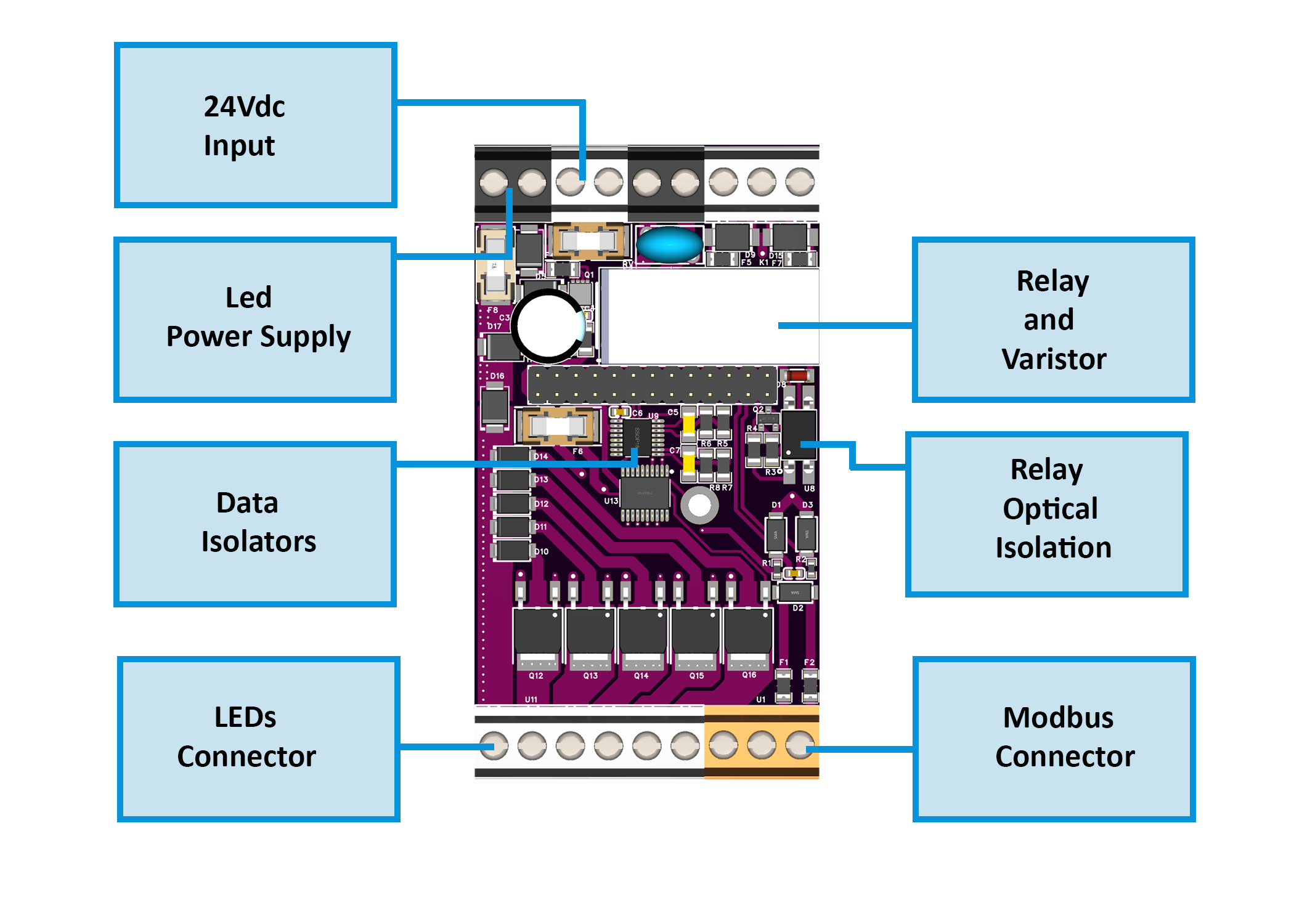
Field Board Layout: RelayBoard_Diagram.png
MCU Board Layout: MCUBoard_Diagram.png
Firmware & Software
Firmware Source Code: RGB-621-R1/Firmware/
WebConfig Tool: ConfigToolPage.html
ESPHome Integration Package: default_rgb_621_r1_plc/
Mechanical Files
Dimensional Drawing: RGB-620-R1Dimensions.png
All design files and documentation are available in the HomeMaster GitHub repository.
Input and Output
Digital Inputs:
Type: Galvanically isolated (ISO1212)
Compatibility: Dry contact or 24V sourcing
Protection: PTC fuses + TVS diodes per channel
PWM Outputs:
Driver: AP9990GH-HF N-channel MOSFETs
Control: 0-100% duty cycle (0-1000 scale)
Protection: PTC fuses, reverse polarity protection
Relay Output:
Type: HF115F mechanical relay
Control: Modbus coil or local mapping
Application: LED driver switching, auxiliary loads
User Interface
2 Buttons: Configurable for relay override (toggle function)
2 LEDs: Configurable steady or blink modes, linked to relay status
Status LEDs: PWR (power), TX/RX (Modbus activity)
Communication Interfaces
Protocol: Modbus RTU
Role: Slave device
Default Settings: Address 3, 19200 baud, 8 data bits, No parity, 1 stop bit
Supported Functions: Read Coils (0x01), Read Discrete Inputs (0x02), Read Holding Registers (0x03), Read Input Registers (0x04), Write Single Coil (0x05), Write Single Register (0x06)
Modbus Address Map
Coils (Read/Write) - Function Codes 0x01, 0x05
| Address | Name | Description |
|---|---|---|
| 00000 | RELAY_CMD | Relay command (1=ON, 0=OFF) |
| 00010 | SAVE_CFG | Save configuration to flash |
| 00011 | RESET | Soft reset device |
Discrete Inputs (Read Only) - Function Code 0x02
| Address | Name | Description |
|---|---|---|
| 10000 | DI1_STATE | Digital Input 1 state |
| 10001 | DI2_STATE | Digital Input 2 state |
| 10010 | RELAY_STATE | Relay actual state |
| 10020-24 | PWM_x_STATE | PWM channel active states |
Holding Registers (Read/Write) - Function Codes 0x03, 0x06
| Address | Name | Description | Range |
|---|---|---|---|
| 40000 | MODEL_ID | Module identifier (0x0621) | RO |
| 40001 | FW_VERSION | Firmware build (YYYYMM) | RO |
| 40002 | MB_ADDR | Modbus address | 1-255 |
| 40003 | MB_BAUD | Baud rate | 0-4 |
| 40010-14 | PWM_x_DUTY | PWM duty cycles | 0-1000 |
| 40020 | DI_EN_MASK | Input enable mask | Bitmask |
| 40022 | RELAY_EN | Relay enable | 0-1 |
| 40030-31 | UPTIME | Uptime seconds | RO |
Input Registers (Read Only) - Function Code 0x04
| Address | Name | Description |
|---|---|---|
| 30000 | DI_STATE_MASK | Input state mask |
| 30001 | PWM_STATE_MASK | PWM state mask |
| 30002 | TEMP_READING | Internal temperature (°C) |
| 30003 | VOLTAGE_READING | Input voltage (mV) |
Home Assistant & ESPHome Integration Guide
Overview
The RGB-621-R1 integrates seamlessly with Home Assistant via ESPHome using the Modbus RTU protocol. This guide covers both quick integration using our pre-built package and manual configuration for advanced users.
Prerequisites
Before starting, ensure you have:
ESPHome device (HomeMaster MiniPLC/MicroPLC or any ESP32/ESP8266 with RS-485)
RS-485 connection between ESP device and RGB-621-R1
24V power to RGB-621-R1 module
Home Assistant with ESPHome add-on installed
Configure Your ESPHome Device
Add this to your ESPHome YAML configuration:
# RS-485 Configuration
uart:
  id: uart_modbus
  tx_pin: GPIO17
  rx_pin: GPIO16
  baud_rate: 19200
  parity: NONE
  stop_bits: 1

modbus:
  id: modbus_bus
  uart_id: uart_modbus

# Import RGB-621-R1 Package
packages:
  rgb_621_r1:
    url: https://github.com/isystemsautomation/HOMEMASTER
    ref: main
    files:
      - path: RGB-621-R1/Firmware/default_rgb_621_r1_plc/default_rgb_621_r1_plc.yaml
        vars:
          rgb_prefix: "Staircase"  # Custom name for your entities
          rgb_id: staircase_module  # Unique internal ID
          rgb_address: 3  # Must match WebConfig Modbus address
    refresh: 1d
Customize Variables
rgb_prefix: Appears in entity names (e.g., "Staircase Relay 1")
rgb_id: Must be unique if adding multiple RGB modules
rgb_address: Set to match your RGB-621-R1 Modbus address (default: 3)
Multiple DIO Modules
For additional modules, duplicate the package block with unique IDs:
packages:
  rgb_2:
    url: https://github.com/isystemsautomation/HOMEMASTER
    ref: main
    files:
      - path: RGB-621-R1/Firmware/default_rgb_621_r1_plc/default_rgb_621_r1_plc.yaml
        vars:
          rgb_prefix: "Kitchen"
          rgb_id: kitchen_module
          rgb_address: 4
    refresh: 1d

  rgb_1:
    url: https://github.com/isystemsautomation/HOMEMASTER
    ref: main
    files:
      - path: RGB-621-R1/Firmware/default_rgb_621_r1_plc/default_rgb_621_r1_plc.yaml
        vars:
          rgb_prefix: "HVAC"
          rgb_id: hvac_module
          rgb_address: 5
    refresh: 1d
Programming
Supported Development Environments
Arduino IDE with RP2350 support
PlatformIO with RP2350 toolchain
MicroPython (community builds available)
Firmware Flashing
Connect USB-C to PC
Hold Buttons 1 + 2 to enter BOOT mode
Upload via:
UF2 drag-and-drop to mounted drive, OR
PlatformIO/Arduino IDE upload
Power off the module for reset
Pin Mapping (Default Firmware)
| Function | GPIO | Description |
|---|---|---|
| PWM_R | GPIO6 | Red channel |
| PWM_G | GPIO11 | Green channel |
| PWM_B | GPIO12 | Blue channel |
| PWM_CW | GPIO7 | Cool White |
| PWM_WW | GPIO8 | Warm White |
| DI1 | GPIO9 | Input 1 |
| DI2 | GPIO10 | Input 2 |
| RELAY | GPIO13 | Relay driver |
| BTN1 | GPIO1 | Button 1 |
| BTN2 | GPIO2 | Button 2 |
| RS485_TX | GPIO4 | Transmit |
| RS485_RX | GPIO5 | Receive |
Related products
These other products might interest you