


RGB-621-R1 RGBCCT Module
Display Name:
RGB-621-R1 RGBCCT Module
RGB-621-R1 — Module for RGB+CCT LED Control
HOMEMASTER – Modular control. Custom logic.
1. Introduction
1.1 Overview of the RGB-621-R1
The RGB-621-R1 is a smart RGB + CCT LED controller module designed for HomeMaster automation systems and other Modbus RTU networks.
It features 5 high-current PWM outputs for RGB and Tunable White (CCT) LED control, 2 isolated digital inputs for wall switches or sensors, and 1 relay output for switching external loads or LED drivers.
Powered by the Raspberry Pi RP2350A microcontroller, the module supports RS-485 (Modbus RTU) communication and configuration via WebConfig over USB-C (Web Serial) — no drivers or external software required.
It connects directly to HomeMaster MicroPLC and MiniPLC controllers or operates as a standalone Modbus slave in any automation network.
Its isolated I/O architecture, dual-board design, and built-in surge and short-circuit protection ensure accurate dimming, stable communication, and reliable operation in demanding home, ambient, or architectural lighting applications.
1.2 Features & Architecture
| Subsystem | Qty | Description |
|---|---|---|
| Digital Inputs | 2 | Galvanically isolated (ISO1212) dry-contact inputs with surge and reverse protection |
| PWM Outputs | 5 | N-channel MOSFET drivers (AP9990GH-HF), 12 V / 24 V LED channels for R / G / B / CW / WW |
| Relay Output | 1 | SPST-NO relay (HF115F/005-1ZS3), 5 V coil, rated 16 A @ 250 VAC / 30 VDC |
| Buttons | 2 | Local control or configuration triggers (SW1 / SW2) |
| LED Indicators | 8 | Power, TX/RX, input, and status LEDs for feedback and diagnostics |
| Modbus RTU | Yes | RS-485 interface via MAX485CSA+T transceiver; 120 Ω termination selectable |
| USB-C | Yes | WebConfig & firmware flashing with PRTR5V0U2X ESD protection |
| Power Input | 24 V DC | Protected by resettable fuses (1206L series), TVS (SMBJ33A), and reverse-blocking (STPS340U) |
| Logic Supply | — | AP64501SP-13 buck (5 V) + AMS1117-3.3 LDO chain |
| MCU | RP2350A | Dual-core Arm Cortex-M33 @ 133 MHz with 32 Mbit QSPI Flash (W25Q32JVUUIQ) |
| Isolation & Protection | — | Galvanic isolation, TVS diodes, PTC fuses, transient suppression on all field I/O |
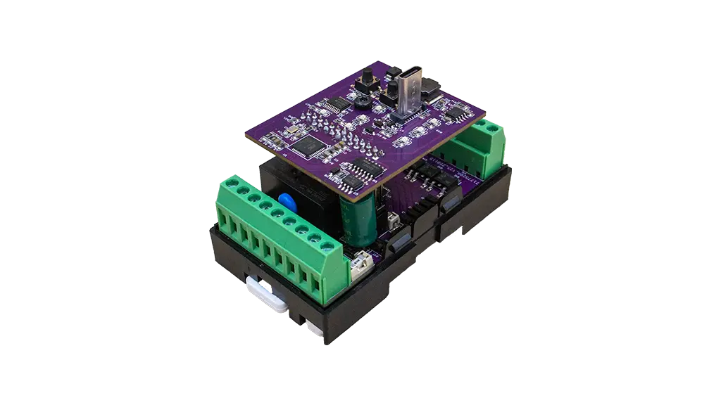
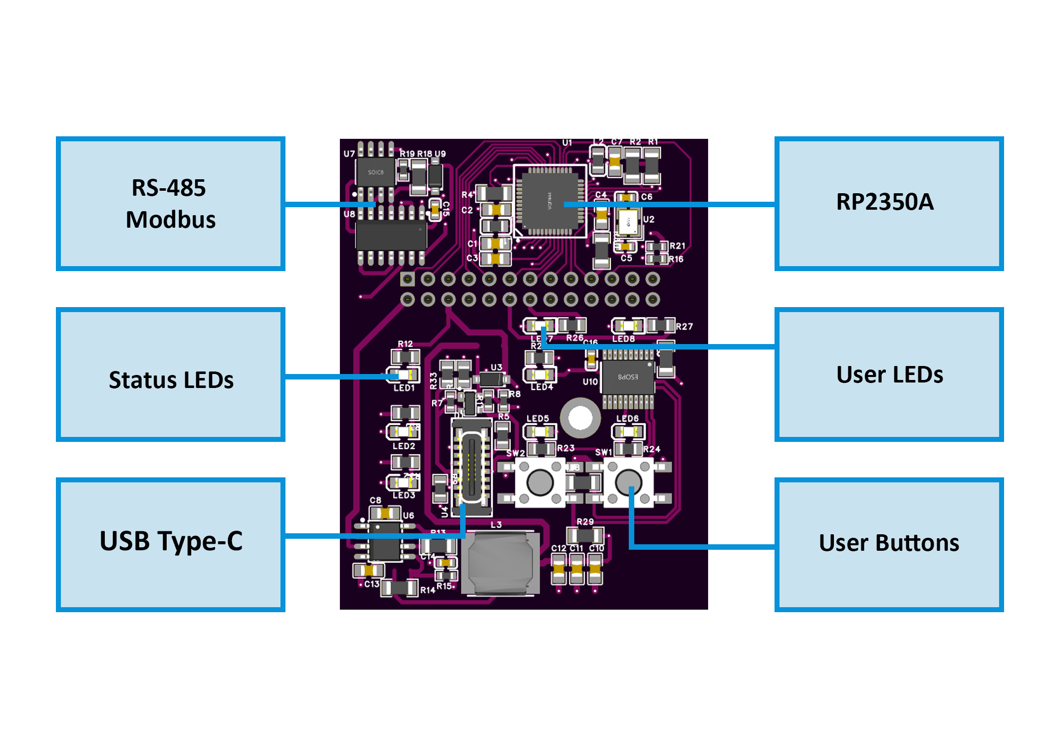
Architecture summary:
- MCU Board: manages logic, USB, Modbus, and power regulation
- Field Board: contains LED drivers, relay circuit, and isolated input section
This modular, two-board design ensures clean signal separation between logic and 24 V field wiring, improving reliability in mixed-voltage installations.
1.3 System Role & Communication
The RGB-621-R1 operates as a Modbus RTU slave on an RS-485 differential bus, typically polled by a HomeMaster controller (MicroPLC / MiniPLC) or other Modbus master.
Each module is assigned a unique Modbus address via WebConfig, supporting up to 32 devices per bus.
Default communication parameters:
- Address: 1
- Baud rate: 19200 bps
- Format: 8 data bits, no parity, 1 stop bit (8N1)
- Termination: 120 Ω enabled at end of bus
- Fail-safe: retains last valid PWM and relay state if communication is lost
The controller periodically polls holding registers to:
- Write PWM duty values for R, G, B, CW, WW channels
- Control the relay output
- Read digital input and status bits
WebConfig enables users to modify address, baud rate, test I/O, calibrate channels, and perform real-time diagnostics — simplifying setup and commissioning.
2. RGB-621-R1 — Technical Specification
2.1 Diagrams & Pinouts
| Diagram |
|---|
 <br>System Block Diagram <br>System Block Diagram |
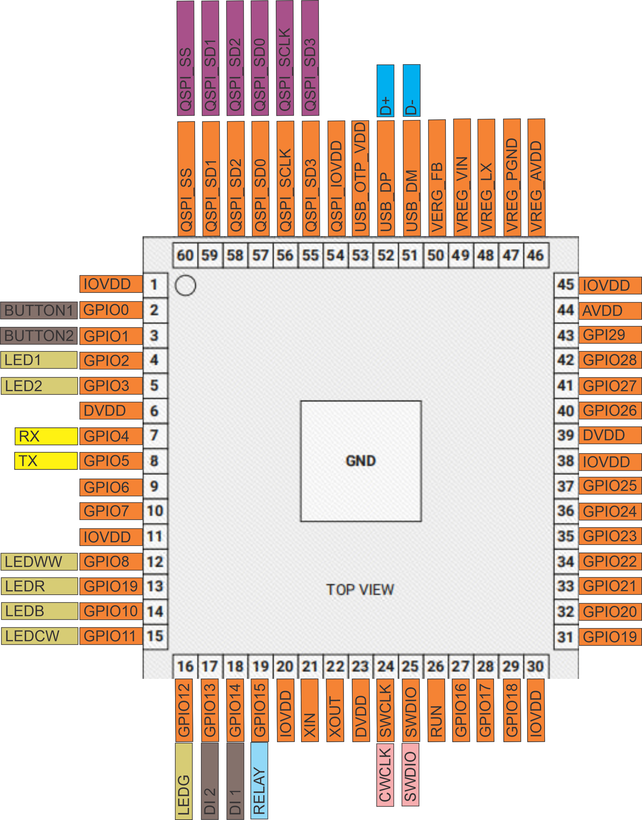 <br>RP2350A MCU Pinout <br>RP2350A MCU Pinout |
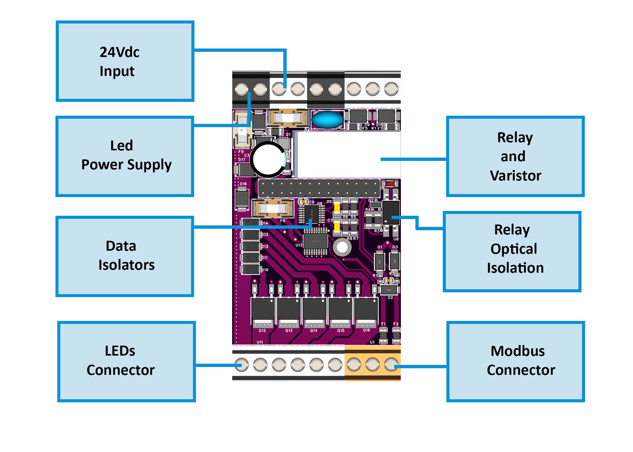 <br>Field Board Layout <br>Field Board Layout |
 <br>MCU Board Layout <br>MCU Board Layout |
2.2 Overview
RGB + CCT LED controller with:
- 5 PWM outputs, 2 isolated digital inputs, 1 relay
- RS-485 (Modbus RTU) slave for HomeMaster controllers or SCADA
- Configurable via USB-C WebConfig
- Compact DIN-rail form factor
2.3 I/O Summary
| Interface | Qty | Notes |
|---|---|---|
| Digital Inputs | 2 | 24 V isolated (ISO1212), dry-contact or sourcing |
| Relay | 1 | SPST-NO, 16 A @ 250 VAC / 30 VDC |
| PWM Outputs | 5 | Low-side MOSFETs (AP9990GH-HF) for R/G/B/CW/WW |
| RS-485 (Modbus) | 1 | MAX485 transceiver, 19200 bps 8N1 default |
| USB-C | 1 | Config & firmware upload (logic only) |
| MCU | 1 | RP2350A @ 133 MHz, 32 Mbit QSPI Flash |
| Buttons / LEDs | — | Local control, TX/RX & status indicators |
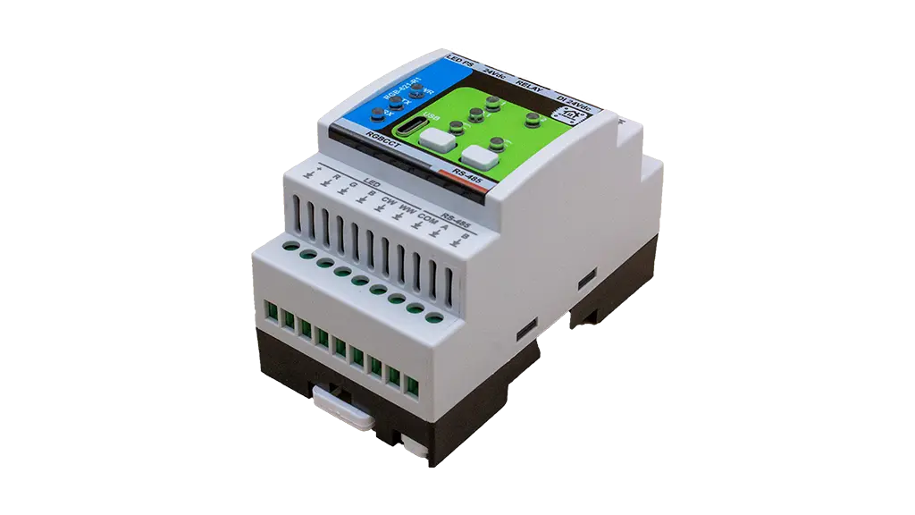
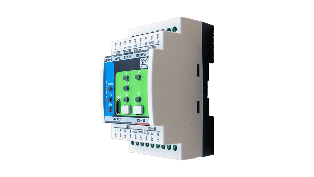
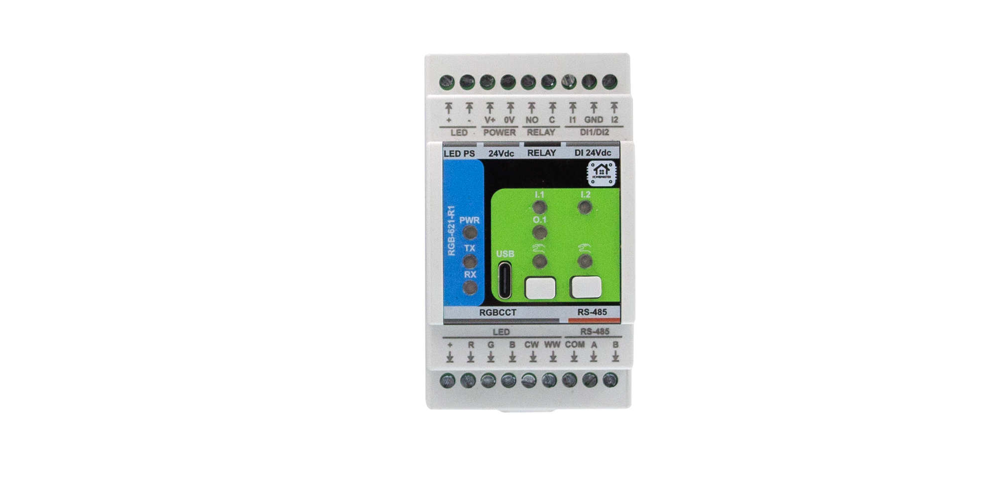
2.4 Terminals & Pinout
Top: V+/0 V (24 V DC input), Relay C/NO, Inputs I1/I2 (+ GND)
Bottom: PWM R/G/B/CW/WW (24 V COM +), RS-485 A/B (+ COM opt.)
2.5 Electrical & Environmental
- Supply: 24 V DC ±10 % (SELV/PELV), ≈ 2 W (no LED load)
- PWM Drive: up to 5 A per channel (25 A max total)
- Relay: 16 A @ 250 VAC / 30 V DC
- Isolation: 3 kVrms (inputs ↔ logic)
- RS-485: 19200 bps 8N1 (default), 115.2 kbps max
- USB-C: WebConfig / firmware only, ESD-protected
- Env.: 0 – 40 °C, ≤ 95 % RH non-condensing
2.6 MCU, Protections & Build
- MCU: Raspberry Pi RP2350A dual-core M33
- Storage: W25Q32 32 Mbit Flash
- Protections: PTC fuses, TVS diodes, reverse polarity & ESD networks
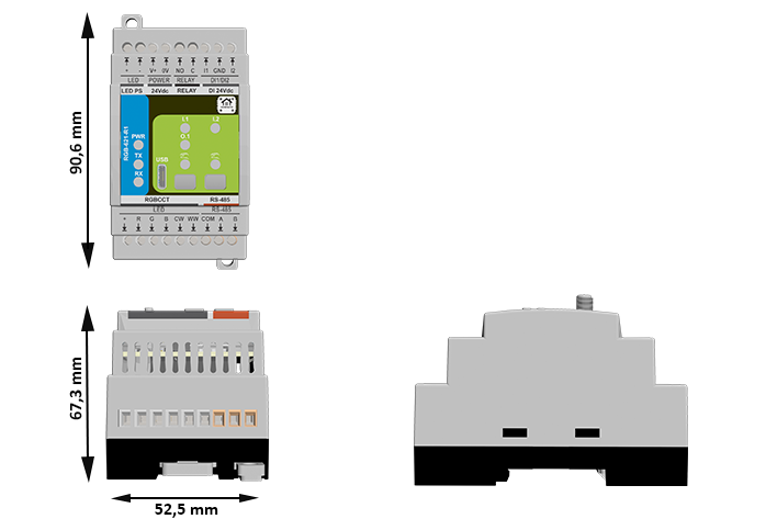
- Mounting: DIN-rail EN 50022 (35 mm), IP20 enclosure
- Dimensions: 52.5 × 90.6 × 67.3 mm · Weight ≈ 0.25 kg
2.7 Absolute Ratings
| Parameter | Min | Typ | Max | Notes |
|---|---|---|---|---|
| Supply Voltage | 20 V | 24 V | 30 V | SELV input protected |
| Power Use | — | 1.85 W | 3.0 W | No LED load |
| Relay Contacts | — | — | 16 A @ 250 VAC / 30 V DC | Resistive |
| PWM Current | — | — | 5 A per ch | External PSU limited |
| RS-485 Rate | — | — | 115.2 kbps | Half-duplex |
| USB Voltage | 4.75 V | 5 V | 5.25 V | Logic only |
| Operating Temp | 0 °C | — | 40 °C | ≤ 95 % RH |
Installer Tip: Use upstream fusing and snubbers for inductive loads.
2.8 Firmware & Operation
- Operates as Modbus RTU slave
- Configurable via WebConfig (USB-C)
- Registers control PWM and Relay; inputs readable as coils/discretes
- Buttons: local test / override
- LED Indicators:
- PWR: Power OK
- TX/RX: Communication activity
- DI1/DI2: Input state
- RUN/ERR: Status / fault pattern
3. Use Cases
The RGB-621-R1 module is primarily designed for multi-channel lighting control but can also be used in broader automation and signaling tasks.
Its combination of isolated inputs, PWM outputs, and a relay makes it suitable for ambient lighting, architectural control, and user-interactive automation.
🏠 Use Case 1 — RGB Scene Control with Wall Switch Inputs
Purpose:
Use two wall switches to trigger and cycle through preset color or brightness scenes stored in the controller.
How it works:
Each digital input acts as a trigger to change the lighting mode or adjust brightness levels.
Setup Steps:
- Connect DI1 and DI2 to wall switches (dry contact).
- Wire RGBW LED strips to PWM outputs R, G, B, CW, WW.
- In WebConfig, assign Modbus address and test LED channels.
- In the MicroPLC / MiniPLC, define scene logic (e.g., DI1 → next scene, DI2 → off).
- Use Modbus holding registers to control PWM duty cycles for each channel.
💡 Use Case 2 — Relay-Based Power Switching for LED Drivers
Purpose:
Control a 24 V LED power supply or auxiliary lighting circuit via the onboard relay.
How it works:
The relay output switches the driver’s DC line or AC supply based on PLC logic or local input triggers.
Setup Steps:
- Connect the relay COM/NO terminals in series with the LED driver’s supply.
- Wire LED outputs to PWM channels for dimming control.
- In WebConfig, enable relay control via Modbus coil.
- Program the controller to energize the relay only when active scenes are running.
- Optionally, use a wall switch on DI1 as a manual override for relay control.
🌈 Use Case 3 — Tunable White (CCT) Control with Daylight Automation
Purpose:
Implement human-centric lighting that adjusts color temperature (CCT) throughout the day.
How it works:
Two PWM channels (CW and WW) mix warm and cool light based on time of day or ambient sensor input.
Setup Steps:
- Connect CW and WW LED strips to respective PWM outputs.
- Define a time-based profile in the controller (morning = warm, midday = cool).
- Use Modbus registers to update CW/WW duty cycles automatically.
- Optionally, map DI1 as a manual “Day/Night” mode toggle.
- Adjust max/min PWM limits in WebConfig for consistent brightness.
🚨 Use Case 4 — Status Indicator / Alarm Signaling
Purpose:
Display system or alarm status using color lighting patterns.
How it works:
The module’s PWM channels can drive RGB indicators or stack lights controlled by alarm flags from the PLC.
Setup Steps:
- Wire a small 12 V RGB LED indicator to PWM outputs R, G, and B.
- Connect the module to the same Modbus bus as the alarm controller.
- Assign registers to display alarm colors (e.g., red = alert, green = normal).
- Use DI1 as a manual alarm acknowledge input.
- Configure the relay as an auxiliary siren or warning signal driver.
🧠 Use Case 5 — Standalone Mood Lighting Controller
Purpose:
Operate ambient RGB lighting locally without an external PLC, using onboard inputs and preloaded logic.
How it works:
The module can store simple input-to-output mapping rules (through WebConfig or firmware) for local lighting control.
Setup Steps:
- Power the module from a 24 V DC supply.
- Connect LED strips to PWM outputs and wall switches to DI1/DI2.
- In WebConfig, set input-to-PWM mapping rules or fading behavior.
- Adjust brightness levels and transition speeds.
- Optionally, connect to Modbus later for centralized control or monitoring.
These examples illustrate how the RGB-621-R1 can serve as both a dedicated lighting driver and a multi-purpose automation node, combining smooth dimming, robust field isolation, and Modbus integration.
4. Safety Information
4.1 General Requirements
| Requirement | Detail |
|---|---|
| Qualified Personnel | Installation, wiring, and servicing must be performed by trained technicians familiar with 24 V DC SELV/PELV control systems. |
| Power Isolation | Always disconnect the 24 V DC supply and RS-485 network before wiring or servicing. |
| Rated Voltages Only | Operate only from a Safety Extra-Low Voltage (SELV/PELV) 24 V DC source. 12 V DC is not supported. Never connect mains (230 V AC) to any terminal. |
| Independent Power | Each controller and I/O module must have its own 24 V DC power supply, sized for its load and fused appropriately. |
| Grounding | Ensure proper protective-earth (PE) connection of the control cabinet and shielded bus cable. |
| Enclosure | Mount the device on a DIN rail inside a dry, clean enclosure. Avoid condensation, dust, or corrosive atmosphere. |
4.2 Installation Practices
DIN-Rail Mounting
- Mount on a 35 mm DIN rail (EN 60715).
- Provide at least 10 mm clearance above/below for airflow and terminal access.
- Route LED-power wiring separately from communication lines.
Electrical Domains
Two distinct domains exist:
- Field Power (24 V DC) — supplies LED drivers, relay, and input circuits.
- Logic Power (5 V / 3.3 V) — internal regulation for MCU, USB, and RS-485.
The field return is GND_FUSED; the logic return is GND.
🟡 Important: Do not externally bridge GND_FUSED and GND.
Isolation between these domains is provided internally through the ISO1212 and SFH6156 devices.
LED Power and Output Wiring
- The LED power rail (+24 V) enters through the protected input (fuses F3/F4, diode D5 STPS340U, surge D6 SMBJ33A).
- It passes the relay K1 (HF115F) and feeds the COM (+24 V) terminal on the bottom connector.
- LED channel outputs (R, G, B, CW, WW) are low-side PWM sinks using AP9990GH-HF MOSFETs.
- Connect LED + to COM, and each color cathode to its respective channel output.
- Only 24 V LED strips (common-anode type) are supported.
Relay Wiring
- Type HF115F (5 V coil, SPST-NO).
- Contact rating: 16 A @ 250 VAC / 30 V DC (resistive).
- For inductive loads, add an external flyback diode or RC snubber.
- Keep relay conductors away from signal wiring.
Digital Input Wiring
- Inputs use ISO1212 galvanic isolation.
- Connect dry contacts or 24 V DC sourcing sensors only.
- Each input path has a PTC fuse (F5/F6), TVS D9, and reverse diodes (D10–D14).
- Do not inject external voltage into DI pins.
- Use shielded twisted-pair cable for runs > 10 m.
4.3 Interface Warnings
⚡ Power Supply (24 V DC)
| Parameter | Specification |
|---|---|
| Nominal Voltage | 24 V DC ± 10 % |
| Input Protection | PTC fuses (F1–F4), reverse-polarity diode (STPS340U), surge TVS (SMBJ33A) |
| Ground Reference | Field return GND_FUSED |
| Isolation | Field side isolated from logic via DC/DC and opto-devices |
| Notes | Use a regulated SELV 24 V DC supply rated ≥ 1 A per module. Each module must have its own isolated 24 V supply rail. |
🟢 Digital Inputs
| Parameter | Specification |
|---|---|
| Type | Galvanically isolated, dry-contact or sourcing 24 V DC input |
| Circuit | ISO1212 receiver with TVS (SMBJ26CA) + PTC protection |
| Operating Range | 9 – 36 V DC (typ. 24 V DC) |
| Isolation | 3 kVrms (input ↔ logic) |
| Notes | For switches or sensors only; debounce handled in firmware. |
🔴 Relay Output
| Parameter | Specification |
|---|---|
| Type | SPST-NO mechanical relay (HF115F/005-1ZS3) |
| Coil Voltage | 5 V DC (via SFH6156 optocoupler + S8050 driver) |
| Contact Rating | 16 A @ 250 VAC / 30 V DC (resistive) |
| Protection | External RC snubber / flyback diode recommended |
| Notes | Keep field wiring separate from logic; observe polarity and isolation boundaries. |
🔵 RS-485 Communication
| Parameter | Specification |
|---|---|
| Transceiver | MAX485CSA+T |
| Bus Type | Differential, multi-drop (A/B lines) |
| Default Settings | 19200 bps · 8N1 |
| Termination | 120 Ω enabled only at end-of-line device |
| Protection | Surge/ESD network integrated |
| Notes | Observe polarity (A = +, B = –). Use shielded twisted-pair cable; ground shield at one end only. |
🧰 USB-C Interface
| Parameter | Specification |
|---|---|
| Function | WebConfig setup & firmware update only |
| Protection | PRTR5V0U2X ESD + CG0603MLC-05E current limiters |
| Supply | 5 V DC from host computer (logic domain) |
| Isolation | Shares logic ground (GND); not isolated from RS-485 logic |
| Notes | Use only when field power is disconnected; not for continuous operation in field. |
⚠️ Important:
• The RGB-621-R1 operates only on 24 V DC SELV/PELV power.
• 12 V DC operation is not supported.
• Each module and controller has its own 24 V DC supply.
• Never connect mains voltage to any terminal.
• Maintain isolation betweenGND_FUSED(field) andGND(logic).
• Follow local electrical codes for fusing and grounding.
5. Installation & Quick Start
5.1 What You Need
| Item | Description |
|---|---|
| Module | RGB-621-R1 LED control module |
| Controller | HomeMaster MicroPLC / MiniPLC or any Modbus RTU master |
| Power Supply (PSU) | Regulated 24 V DC SELV/PELV, sized for module and LED load |
| Cables | 1× USB-C cable (for setup), 1× twisted-pair RS-485 cable |
| Software | Any Chromium-based browser (Chrome/Edge) with Web Serial support for WebConfig |
| Optional | Shielded wiring for long RS-485 runs, DIN-rail enclosure, terminal labels |
5.2 Power
-
The RGB-621-R1 operates exclusively from a 24 V DC SELV/PELV supply.
Connect the +24 V and 0 V (GND) to the top power terminals marked V+ and 0V or LED PS. -
The LED strip’s positive rail (+24 V) is routed internally through:
- PTC fuses (F3/F4) for over-current protection
- Reverse-polarity diode (STPS340U)
- Surge suppressor (SMBJ33A)
- Relay K1 (HF115F), which switches the LED power output (COM terminal)
The LED channels (R/G/B/CW/WW) act as low-side PWM sinks, and the LED strip must be 24 V common-anode.
-
Current consumption (typical):
- Logic + RS-485: ≈ 100 mA
- Relay coil: ≈ 30 mA (active)
- LED load: dependent on connected strips (sized per external 24 V LED PSU)
-
Ground references:
GND_FUSED→ field ground for LED and inputsGND→ logic/USB ground
These are internally isolated — do not tie them together externally.
4.3 Communication
RS-485 Pinout (bottom connector):
| Terminal | Signal | Description |
|---|---|---|
| A | RS-485 A (+) | Non-inverting line |
| B | RS-485 B (–) | Inverting line |
| COM | Common reference (optional) | Field ground reference (GND_FUSED) for long bus runs |
-
Use a twisted-pair shielded cable (e.g., Cat-5 or RS-485 grade).
Connect the shield to protective earth (PE) at one end only. -
Network topology:
Daisy-chain (bus) — no star wiring.
Enable the 120 Ω termination resistor only at the last module in the chain. -
Default Modbus settings:
- Address: 1
- Baud rate: 19200 bps
- Data format: 8 data bits, no parity, 1 stop bit (8N1)
-
Configuration:
- Connect via USB-C and open WebConfig in a Chromium-based browser.
- Set module address, baud rate, and optional relay/input parameters.
- Save settings to non-volatile memory.
-
Ground reference use:
- In most RS-485 systems, differential A/B are sufficient.
- The COM terminal may be connected between devices only if bus transceivers require a shared reference (rare in modern isolated networks).
⚙️ Quick Summary
- Mount the module on a DIN rail.
- Wire +24 V and 0 V to the LED PS terminals.
- Connect LED strips (common-anode to COM, cathodes to R/G/B/CW/WW).
- Wire RS-485 A/B to the controller.
- Plug in USB-C, open WebConfig, assign address, set baudrate, test outputs.
- Disconnect USB, power up the system, and verify Modbus communication.
5.4 Installation & Wiring
Use diagrams and explain:
- Inputs
- Relays
- Sensor rails (12/5V)
- RS-485 terminals
- USB port
5.5 Software & UI Configuration
Cover:
- WebConfig setup (address, baud)
- Input enable/invert/group
- Relay logic mode (group/manual)
- LED and Button mapping
5.6 Getting Started
Summarize steps in 3 phases:
- Wiring
- Configuration
- Integration
6. Modbus RTU Communication
Include:
- Address range and map
- Input/holding register layout
- Coil/discrete inputs
- Register use examples
- Polling recommendations
7. ESPHome Integration Guide
Only if supported. Cover:
- YAML setup (
uart,modbus,package) - Entity list (inputs, relays, buttons, LEDs)
- Acknowledge, override controls
- Home Assistant integration tips
8. Programming & Customization (RGB-621-R1)
8.1 Supported Languages
- Arduino (RP2350 core)
- C/C++ (PIO / SDK)
- MicroPython
8.2 Flashing
USB-C (Web Serial / CDC)
- Connect a USB-C cable from your PC to the module’s USB port.
- Enter BOOT mode: press Button 1 + Button 2 together (see photo below).
- Flash using PlatformIO or Arduino IDE (serial upload).
- When flashing completes, disconnect and power-cycle the module.
Reset: this module does not have a button combo for reset.
To reset, remove 24 VDC power for ≥5 s and re-apply.
PlatformIO / Arduino IDE setup
- Board/MCU: Raspberry Pi RP2350 / Generic RP235x
- USB upload: Serial (CDC)
- Flash layout (Arduino): e.g. 2 MB (Sketch 1 MB / FS 1 MB)
- Recommended libs (Arduino examples):
ModbusSerial(RTU master/slave helpers)Arduino_JSONLittleFSSimpleWebSerial(for WebConfig bridge)
Buttons reference (RGB-621-R1 front)
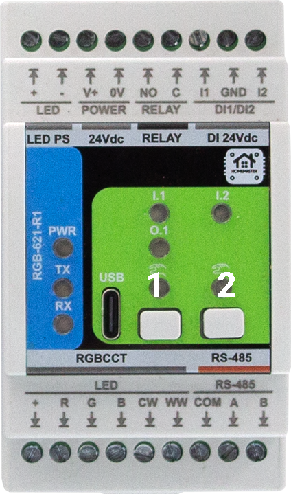
- Button 1 + Button 2 → BOOT mode
- Reset → power-cycle 24 VDC for ≥5 s
8.3 Firmware Updates
- Open the project in PlatformIO or Arduino IDE.
- Put device in BOOT (Button 1+2) and upload the new build.
- Configuration persistence: device settings (address/baud, channel trims, etc.) are stored in flash and kept across updates unless you explicitly erase.
- Recovery: if the device won’t enumerate, power-cycle 24 VDC (≥5 s) and retry BOOT (1+2). If needed, flash a minimal “factory” image first, then restore config via WebConfig backup.
9. Maintenance & Troubleshooting
9.1 Status LEDs (front panel)
| LED | Meaning |
|---|---|
| PWR | Steady when powered and firmware is running. |
| TX | Blinks on Modbus transmit. |
| RX | Blinks on Modbus receive. |
| I.1 / I.2 | Reflect isolated input states. |
| RUN/ERR (if present) | Heartbeat / fault pattern (refer to firmware notes). |
9.2 Resets & Modes
- BOOT mode: Button 1 + Button 2 (for flashing).
- Reset: remove 24 VDC for ≥5 s and re-apply.
9.3 Common Issues
- No communication (TX/RX dark):
Check A/B polarity, termination at bus ends (120 Ω), baud/ID match, and shared COM reference if separate PSUs. - Relay won’t trigger:
Confirm Modbus control vs. local override mode, verify coil/state in WebConfig, and ensure external wiring is on C/NO (dry contact). Add snubber for inductive loads. - LED channels do not light:
Verify COM (+24 V) to strip, channel cathodes on R/G/B/CW/WW, correct polarity, and adequate 24 V PSU sizing. - Inputs not detected:
Use DI 24Vdc terminals (I1/I2 with GND). Confirm sensor type (dry contact or 24 V sourcing) and debounce/invert settings in WebConfig. - USB not detected:
Use a data-capable USB-C cable; close any app holding the port; re-enter BOOT (1+2).
10. Open Source & Licensing
- Hardware: CERN-OHL-W v2
- Firmware: GPLv3
- Config Tools & examples: MIT (unless stated otherwise)
11. Downloads
- Repository (module path):
RGB-621-R1on GitHub - Firmware & examples:
RGB-621-R1/Firmware/ - WebConfig (HTML page):
RGB-621-R1/Firmware/ConfigToolPage.html - Schematics (PDF):
RGB-621-R1/Schematics/ - Datasheet & docs:
RGB-621-R1/Manuals/ - Images & diagrams:
RGB-621-R1/Images/
12. Support
- Official Support: https://www.home-master.eu/support
- WebConfig Tool (RGB-621-R1): https://www.home-master.eu/configtool-rgb-621-r1
- YouTube: https://youtube.com/@HomeMaster
- Hackster: https://hackster.io/homemaster
- Reddit: https://reddit.com/r/HomeMaster
- Instagram: https://instagram.com/home_master.eu
RGB-621-R1 — Module for RGB+CCT LED Control
HOMEMASTER – Modular control. Custom logic.
1. Introduction
1.1 Overview of the RGB-621-R1
The RGB-621-R1 is a smart RGB + CCT LED controller module designed for HomeMaster automation systems and other Modbus RTU networks.
It features 5 high-current PWM outputs for RGB and Tunable White (CCT) LED control, 2 isolated digital inputs for wall switches or sensors, and 1 relay output for switching external loads or LED drivers.
Powered by the Raspberry Pi RP2350A microcontroller, the module supports RS-485 (Modbus RTU) communication and configuration via WebConfig over USB-C (Web Serial) — no drivers or external software required.
It connects directly to HomeMaster MicroPLC and MiniPLC controllers or operates as a standalone Modbus slave in any automation network.
Its isolated I/O architecture, dual-board design, and built-in surge and short-circuit protection ensure accurate dimming, stable communication, and reliable operation in demanding home, ambient, or architectural lighting applications.
1.2 Features & Architecture
| Subsystem | Qty | Description |
|---|---|---|
| Digital Inputs | 2 | Galvanically isolated (ISO1212) dry-contact inputs with surge and reverse protection |
| PWM Outputs | 5 | N-channel MOSFET drivers (AP9990GH-HF), 12 V / 24 V LED channels for R / G / B / CW / WW |
| Relay Output | 1 | SPST-NO relay (HF115F/005-1ZS3), 5 V coil, rated 16 A @ 250 VAC / 30 VDC |
| Buttons | 2 | Local control or configuration triggers (SW1 / SW2) |
| LED Indicators | 8 | Power, TX/RX, input, and status LEDs for feedback and diagnostics |
| Modbus RTU | Yes | RS-485 interface via MAX485CSA+T transceiver; 120 Ω termination selectable |
| USB-C | Yes | WebConfig & firmware flashing with PRTR5V0U2X ESD protection |
| Power Input | 24 V DC | Protected by resettable fuses (1206L series), TVS (SMBJ33A), and reverse-blocking (STPS340U) |
| Logic Supply | — | AP64501SP-13 buck (5 V) + AMS1117-3.3 LDO chain |
| MCU | RP2350A | Dual-core Arm Cortex-M33 @ 133 MHz with 32 Mbit QSPI Flash (W25Q32JVUUIQ) |
| Isolation & Protection | — | Galvanic isolation, TVS diodes, PTC fuses, transient suppression on all field I/O |
Architecture summary:
- MCU Board: manages logic, USB, Modbus, and power regulation
- Field Board: contains LED drivers, relay circuit, and isolated input section
This modular, two-board design ensures clean signal separation between logic and 24 V field wiring, improving reliability in mixed-voltage installations.
1.3 System Role & Communication
The RGB-621-R1 operates as a Modbus RTU slave on an RS-485 differential bus, typically polled by a HomeMaster controller (MicroPLC / MiniPLC) or other Modbus master.
Each module is assigned a unique Modbus address via WebConfig, supporting up to 32 devices per bus.
Default communication parameters:
- Address: 1
- Baud rate: 19200 bps
- Format: 8 data bits, no parity, 1 stop bit (8N1)
- Termination: 120 Ω enabled at end of bus
- Fail-safe: retains last valid PWM and relay state if communication is lost
The controller periodically polls holding registers to:
- Write PWM duty values for R, G, B, CW, WW channels
- Control the relay output
- Read digital input and status bits
WebConfig enables users to modify address, baud rate, test I/O, calibrate channels, and perform real-time diagnostics — simplifying setup and commissioning.
2. RGB-621-R1 — Technical Specification
2.1 Diagrams & Pinouts
| Diagram |
|---|
| <br>System Block Diagram |
| <br>RP2350A MCU Pinout |
| <br>Field Board Layout |
| <br>MCU Board Layout |
2.2 Overview
RGB + CCT LED controller with:
- 5 PWM outputs, 2 isolated digital inputs, 1 relay
- RS-485 (Modbus RTU) slave for HomeMaster controllers or SCADA
- Configurable via USB-C WebConfig
- Compact DIN-rail form factor
2.3 I/O Summary
| Interface | Qty | Notes |
|---|---|---|
| Digital Inputs | 2 | 24 V isolated (ISO1212), dry-contact or sourcing |
| Relay | 1 | SPST-NO, 16 A @ 250 VAC / 30 VDC |
| PWM Outputs | 5 | Low-side MOSFETs (AP9990GH-HF) for R/G/B/CW/WW |
| RS-485 (Modbus) | 1 | MAX485 transceiver, 19200 bps 8N1 default |
| USB-C | 1 | Config & firmware upload (logic only) |
| MCU | 1 | RP2350A @ 133 MHz, 32 Mbit QSPI Flash |
| Buttons / LEDs | — | Local control, TX/RX & status indicators |
2.4 Terminals & Pinout
Top: V+/0 V (24 V DC input), Relay C/NO, Inputs I1/I2 (+ GND)
Bottom: PWM R/G/B/CW/WW (24 V COM +), RS-485 A/B (+ COM opt.)
2.5 Electrical & Environmental
- Supply: 24 V DC ±10 % (SELV/PELV), ≈ 2 W (no LED load)
- PWM Drive: up to 5 A per channel (25 A max total)
- Relay: 16 A @ 250 VAC / 30 V DC
- Isolation: 3 kVrms (inputs ↔ logic)
- RS-485: 19200 bps 8N1 (default), 115.2 kbps max
- USB-C: WebConfig / firmware only, ESD-protected
- Env.: 0 – 40 °C, ≤ 95 % RH non-condensing
2.6 MCU, Protections & Build
- MCU: Raspberry Pi RP2350A dual-core M33
- Storage: W25Q32 32 Mbit Flash
- Protections: PTC fuses, TVS diodes, reverse polarity & ESD networks
- Mounting: DIN-rail EN 50022 (35 mm), IP20 enclosure
- Dimensions: 52.5 × 90.6 × 67.3 mm · Weight ≈ 0.25 kg
2.7 Absolute Ratings
| Parameter | Min | Typ | Max | Notes |
|---|---|---|---|---|
| Supply Voltage | 20 V | 24 V | 30 V | SELV input protected |
| Power Use | — | 1.85 W | 3.0 W | No LED load |
| Relay Contacts | — | — | 16 A @ 250 VAC / 30 V DC | Resistive |
| PWM Current | — | — | 5 A per ch | External PSU limited |
| RS-485 Rate | — | — | 115.2 kbps | Half-duplex |
| USB Voltage | 4.75 V | 5 V | 5.25 V | Logic only |
| Operating Temp | 0 °C | — | 40 °C | ≤ 95 % RH |
Installer Tip: Use upstream fusing and snubbers for inductive loads.
2.8 Firmware & Operation
- Operates as Modbus RTU slave
- Configurable via WebConfig (USB-C)
- Registers control PWM and Relay; inputs readable as coils/discretes
- Buttons: local test / override
- LED Indicators:
- PWR: Power OK
- TX/RX: Communication activity
- DI1/DI2: Input state
- RUN/ERR: Status / fault pattern
3. Use Cases
The RGB-621-R1 module is primarily designed for multi-channel lighting control but can also be used in broader automation and signaling tasks.
Its combination of isolated inputs, PWM outputs, and a relay makes it suitable for ambient lighting, architectural control, and user-interactive automation.
🏠 Use Case 1 — RGB Scene Control with Wall Switch Inputs
Purpose:
Use two wall switches to trigger and cycle through preset color or brightness scenes stored in the controller.
How it works:
Each digital input acts as a trigger to change the lighting mode or adjust brightness levels.
Setup Steps:
- Connect DI1 and DI2 to wall switches (dry contact).
- Wire RGBW LED strips to PWM outputs R, G, B, CW, WW.
- In WebConfig, assign Modbus address and test LED channels.
- In the MicroPLC / MiniPLC, define scene logic (e.g., DI1 → next scene, DI2 → off).
- Use Modbus holding registers to control PWM duty cycles for each channel.
💡 Use Case 2 — Relay-Based Power Switching for LED Drivers
Purpose:
Control a 24 V LED power supply or auxiliary lighting circuit via the onboard relay.
How it works:
The relay output switches the driver’s DC line or AC supply based on PLC logic or local input triggers.
Setup Steps:
- Connect the relay COM/NO terminals in series with the LED driver’s supply.
- Wire LED outputs to PWM channels for dimming control.
- In WebConfig, enable relay control via Modbus coil.
- Program the controller to energize the relay only when active scenes are running.
- Optionally, use a wall switch on DI1 as a manual override for relay control.
🌈 Use Case 3 — Tunable White (CCT) Control with Daylight Automation
Purpose:
Implement human-centric lighting that adjusts color temperature (CCT) throughout the day.
How it works:
Two PWM channels (CW and WW) mix warm and cool light based on time of day or ambient sensor input.
Setup Steps:
- Connect CW and WW LED strips to respective PWM outputs.
- Define a time-based profile in the controller (morning = warm, midday = cool).
- Use Modbus registers to update CW/WW duty cycles automatically.
- Optionally, map DI1 as a manual “Day/Night” mode toggle.
- Adjust max/min PWM limits in WebConfig for consistent brightness.
🚨 Use Case 4 — Status Indicator / Alarm Signaling
Purpose:
Display system or alarm status using color lighting patterns.
How it works:
The module’s PWM channels can drive RGB indicators or stack lights controlled by alarm flags from the PLC.
Setup Steps:
- Wire a small 12 V RGB LED indicator to PWM outputs R, G, and B.
- Connect the module to the same Modbus bus as the alarm controller.
- Assign registers to display alarm colors (e.g., red = alert, green = normal).
- Use DI1 as a manual alarm acknowledge input.
- Configure the relay as an auxiliary siren or warning signal driver.
🧠 Use Case 5 — Standalone Mood Lighting Controller
Purpose:
Operate ambient RGB lighting locally without an external PLC, using onboard inputs and preloaded logic.
How it works:
The module can store simple input-to-output mapping rules (through WebConfig or firmware) for local lighting control.
Setup Steps:
- Power the module from a 24 V DC supply.
- Connect LED strips to PWM outputs and wall switches to DI1/DI2.
- In WebConfig, set input-to-PWM mapping rules or fading behavior.
- Adjust brightness levels and transition speeds.
- Optionally, connect to Modbus later for centralized control or monitoring.
These examples illustrate how the RGB-621-R1 can serve as both a dedicated lighting driver and a multi-purpose automation node, combining smooth dimming, robust field isolation, and Modbus integration.
4. Safety Information
4.1 General Requirements
| Requirement | Detail |
|---|---|
| Qualified Personnel | Installation, wiring, and servicing must be performed by trained technicians familiar with 24 V DC SELV/PELV control systems. |
| Power Isolation | Always disconnect the 24 V DC supply and RS-485 network before wiring or servicing. |
| Rated Voltages Only | Operate only from a Safety Extra-Low Voltage (SELV/PELV) 24 V DC source. 12 V DC is not supported. Never connect mains (230 V AC) to any terminal. |
| Independent Power | Each controller and I/O module must have its own 24 V DC power supply, sized for its load and fused appropriately. |
| Grounding | Ensure proper protective-earth (PE) connection of the control cabinet and shielded bus cable. |
| Enclosure | Mount the device on a DIN rail inside a dry, clean enclosure. Avoid condensation, dust, or corrosive atmosphere. |
4.2 Installation Practices
DIN-Rail Mounting
- Mount on a 35 mm DIN rail (EN 60715).
- Provide at least 10 mm clearance above/below for airflow and terminal access.
- Route LED-power wiring separately from communication lines.
Electrical Domains
Two distinct domains exist:
- Field Power (24 V DC) — supplies LED drivers, relay, and input circuits.
- Logic Power (5 V / 3.3 V) — internal regulation for MCU, USB, and RS-485.
The field return is GND_FUSED; the logic return is GND.
🟡 Important: Do not externally bridge GND_FUSED and GND.
Isolation between these domains is provided internally through the ISO1212 and SFH6156 devices.
LED Power and Output Wiring
- The LED power rail (+24 V) enters through the protected input (fuses F3/F4, diode D5 STPS340U, surge D6 SMBJ33A).
- It passes the relay K1 (HF115F) and feeds the COM (+24 V) terminal on the bottom connector.
- LED channel outputs (R, G, B, CW, WW) are low-side PWM sinks using AP9990GH-HF MOSFETs.
- Connect LED + to COM, and each color cathode to its respective channel output.
- Only 24 V LED strips (common-anode type) are supported.
Relay Wiring
- Type HF115F (5 V coil, SPST-NO).
- Contact rating: 16 A @ 250 VAC / 30 V DC (resistive).
- For inductive loads, add an external flyback diode or RC snubber.
- Keep relay conductors away from signal wiring.
Digital Input Wiring
- Inputs use ISO1212 galvanic isolation.
- Connect dry contacts or 24 V DC sourcing sensors only.
- Each input path has a PTC fuse (F5/F6), TVS D9, and reverse diodes (D10–D14).
- Do not inject external voltage into DI pins.
- Use shielded twisted-pair cable for runs > 10 m.
4.3 Interface Warnings
⚡ Power Supply (24 V DC)
| Parameter | Specification |
|---|---|
| Nominal Voltage | 24 V DC ± 10 % |
| Input Protection | PTC fuses (F1–F4), reverse-polarity diode (STPS340U), surge TVS (SMBJ33A) |
| Ground Reference | Field return GND_FUSED |
| Isolation | Field side isolated from logic via DC/DC and opto-devices |
| Notes | Use a regulated SELV 24 V DC supply rated ≥ 1 A per module. Each module must have its own isolated 24 V supply rail. |
🟢 Digital Inputs
| Parameter | Specification |
|---|---|
| Type | Galvanically isolated, dry-contact or sourcing 24 V DC input |
| Circuit | ISO1212 receiver with TVS (SMBJ26CA) + PTC protection |
| Operating Range | 9 – 36 V DC (typ. 24 V DC) |
| Isolation | 3 kVrms (input ↔ logic) |
| Notes | For switches or sensors only; debounce handled in firmware. |
🔴 Relay Output
| Parameter | Specification |
|---|---|
| Type | SPST-NO mechanical relay (HF115F/005-1ZS3) |
| Coil Voltage | 5 V DC (via SFH6156 optocoupler + S8050 driver) |
| Contact Rating | 16 A @ 250 VAC / 30 V DC (resistive) |
| Protection | External RC snubber / flyback diode recommended |
| Notes | Keep field wiring separate from logic; observe polarity and isolation boundaries. |
🔵 RS-485 Communication
| Parameter | Specification |
|---|---|
| Transceiver | MAX485CSA+T |
| Bus Type | Differential, multi-drop (A/B lines) |
| Default Settings | 19200 bps · 8N1 |
| Termination | 120 Ω enabled only at end-of-line device |
| Protection | Surge/ESD network integrated |
| Notes | Observe polarity (A = +, B = –). Use shielded twisted-pair cable; ground shield at one end only. |
🧰 USB-C Interface
| Parameter | Specification |
|---|---|
| Function | WebConfig setup & firmware update only |
| Protection | PRTR5V0U2X ESD + CG0603MLC-05E current limiters |
| Supply | 5 V DC from host computer (logic domain) |
| Isolation | Shares logic ground (GND); not isolated from RS-485 logic |
| Notes | Use only when field power is disconnected; not for continuous operation in field. |
⚠️ Important:
• The RGB-621-R1 operates only on 24 V DC SELV/PELV power.
• 12 V DC operation is not supported.
• Each module and controller has its own 24 V DC supply.
• Never connect mains voltage to any terminal.
• Maintain isolation betweenGND_FUSED(field) andGND(logic).
• Follow local electrical codes for fusing and grounding.
5. Installation & Quick Start
5.1 What You Need
| Item | Description |
|---|---|
| Module | RGB-621-R1 LED control module |
| Controller | HomeMaster MicroPLC / MiniPLC or any Modbus RTU master |
| Power Supply (PSU) | Regulated 24 V DC SELV/PELV, sized for module and LED load |
| Cables | 1× USB-C cable (for setup), 1× twisted-pair RS-485 cable |
| Software | Any Chromium-based browser (Chrome/Edge) with Web Serial support for WebConfig |
| Optional | Shielded wiring for long RS-485 runs, DIN-rail enclosure, terminal labels |
5.2 Power
-
The RGB-621-R1 operates exclusively from a 24 V DC SELV/PELV supply.
Connect the +24 V and 0 V (GND) to the top power terminals marked V+ and 0V or LED PS. -
The LED strip’s positive rail (+24 V) is routed internally through:
- PTC fuses (F3/F4) for over-current protection
- Reverse-polarity diode (STPS340U)
- Surge suppressor (SMBJ33A)
- Relay K1 (HF115F), which switches the LED power output (COM terminal)
The LED channels (R/G/B/CW/WW) act as low-side PWM sinks, and the LED strip must be 24 V common-anode.
-
Current consumption (typical):
- Logic + RS-485: ≈ 100 mA
- Relay coil: ≈ 30 mA (active)
- LED load: dependent on connected strips (sized per external 24 V LED PSU)
-
Ground references:
GND_FUSED→ field ground for LED and inputsGND→ logic/USB ground
These are internally isolated — do not tie them together externally.
4.3 Communication
RS-485 Pinout (bottom connector):
| Terminal | Signal | Description |
|---|---|---|
| A | RS-485 A (+) | Non-inverting line |
| B | RS-485 B (–) | Inverting line |
| COM | Common reference (optional) | Field ground reference (GND_FUSED) for long bus runs |
-
Use a twisted-pair shielded cable (e.g., Cat-5 or RS-485 grade).
Connect the shield to protective earth (PE) at one end only. -
Network topology:
Daisy-chain (bus) — no star wiring.
Enable the 120 Ω termination resistor only at the last module in the chain. -
Default Modbus settings:
- Address: 1
- Baud rate: 19200 bps
- Data format: 8 data bits, no parity, 1 stop bit (8N1)
-
Configuration:
- Connect via USB-C and open WebConfig in a Chromium-based browser.
- Set module address, baud rate, and optional relay/input parameters.
- Save settings to non-volatile memory.
-
Ground reference use:
- In most RS-485 systems, differential A/B are sufficient.
- The COM terminal may be connected between devices only if bus transceivers require a shared reference (rare in modern isolated networks).
⚙️ Quick Summary
- Mount the module on a DIN rail.
- Wire +24 V and 0 V to the LED PS terminals.
- Connect LED strips (common-anode to COM, cathodes to R/G/B/CW/WW).
- Wire RS-485 A/B to the controller.
- Plug in USB-C, open WebConfig, assign address, set baudrate, test outputs.
- Disconnect USB, power up the system, and verify Modbus communication.
5.4 Installation & Wiring
Use diagrams and explain:
- Inputs
- Relays
- Sensor rails (12/5V)
- RS-485 terminals
- USB port
5.5 Software & UI Configuration
Cover:
- WebConfig setup (address, baud)
- Input enable/invert/group
- Relay logic mode (group/manual)
- LED and Button mapping
5.6 Getting Started
Summarize steps in 3 phases:
- Wiring
- Configuration
- Integration
6. Modbus RTU Communication
Include:
- Address range and map
- Input/holding register layout
- Coil/discrete inputs
- Register use examples
- Polling recommendations
7. ESPHome Integration Guide
Only if supported. Cover:
- YAML setup (
uart,modbus,package) - Entity list (inputs, relays, buttons, LEDs)
- Acknowledge, override controls
- Home Assistant integration tips
8. Programming & Customization (RGB-621-R1)
8.1 Supported Languages
- Arduino (RP2350 core)
- C/C++ (PIO / SDK)
- MicroPython
8.2 Flashing
USB-C (Web Serial / CDC)
- Connect a USB-C cable from your PC to the module’s USB port.
- Enter BOOT mode: press Button 1 + Button 2 together (see photo below).
- Flash using PlatformIO or Arduino IDE (serial upload).
- When flashing completes, disconnect and power-cycle the module.
Reset: this module does not have a button combo for reset.
To reset, remove 24 VDC power for ≥5 s and re-apply.
PlatformIO / Arduino IDE setup
- Board/MCU: Raspberry Pi RP2350 / Generic RP235x
- USB upload: Serial (CDC)
- Flash layout (Arduino): e.g. 2 MB (Sketch 1 MB / FS 1 MB)
- Recommended libs (Arduino examples):
ModbusSerial(RTU master/slave helpers)Arduino_JSONLittleFSSimpleWebSerial(for WebConfig bridge)
Buttons reference (RGB-621-R1 front)
- Button 1 + Button 2 → BOOT mode
- Reset → power-cycle 24 VDC for ≥5 s
8.3 Firmware Updates
- Open the project in PlatformIO or Arduino IDE.
- Put device in BOOT (Button 1+2) and upload the new build.
- Configuration persistence: device settings (address/baud, channel trims, etc.) are stored in flash and kept across updates unless you explicitly erase.
- Recovery: if the device won’t enumerate, power-cycle 24 VDC (≥5 s) and retry BOOT (1+2). If needed, flash a minimal “factory” image first, then restore config via WebConfig backup.
9. Maintenance & Troubleshooting
9.1 Status LEDs (front panel)
| LED | Meaning |
|---|---|
| PWR | Steady when powered and firmware is running. |
| TX | Blinks on Modbus transmit. |
| RX | Blinks on Modbus receive. |
| I.1 / I.2 | Reflect isolated input states. |
| RUN/ERR (if present) | Heartbeat / fault pattern (refer to firmware notes). |
9.2 Resets & Modes
- BOOT mode: Button 1 + Button 2 (for flashing).
- Reset: remove 24 VDC for ≥5 s and re-apply.
9.3 Common Issues
- No communication (TX/RX dark):
Check A/B polarity, termination at bus ends (120 Ω), baud/ID match, and shared COM reference if separate PSUs. - Relay won’t trigger:
Confirm Modbus control vs. local override mode, verify coil/state in WebConfig, and ensure external wiring is on C/NO (dry contact). Add snubber for inductive loads. - LED channels do not light:
Verify COM (+24 V) to strip, channel cathodes on R/G/B/CW/WW, correct polarity, and adequate 24 V PSU sizing. - Inputs not detected:
Use DI 24Vdc terminals (I1/I2 with GND). Confirm sensor type (dry contact or 24 V sourcing) and debounce/invert settings in WebConfig. - USB not detected:
Use a data-capable USB-C cable; close any app holding the port; re-enter BOOT (1+2).
10. Open Source & Licensing
- Hardware: CERN-OHL-W v2
- Firmware: GPLv3
- Config Tools & examples: MIT (unless stated otherwise)
11. Downloads
- Repository (module path):
RGB-621-R1on GitHub - Firmware & examples:
RGB-621-R1/Firmware/ - WebConfig (HTML page):
RGB-621-R1/Firmware/ConfigToolPage.html - Schematics (PDF):
RGB-621-R1/Schematics/ - Datasheet & docs:
RGB-621-R1/Manuals/ - Images & diagrams:
RGB-621-R1/Images/
12. Support
- Official Support: https://www.home-master.eu/support
- WebConfig Tool (RGB-621-R1): https://www.home-master.eu/configtool-rgb-621-r1
- YouTube: https://youtube.com/@HomeMaster
- Hackster: https://hackster.io/homemaster
- Reddit: https://reddit.com/r/HomeMaster
- Instagram: https://instagram.com/home_master.eu