
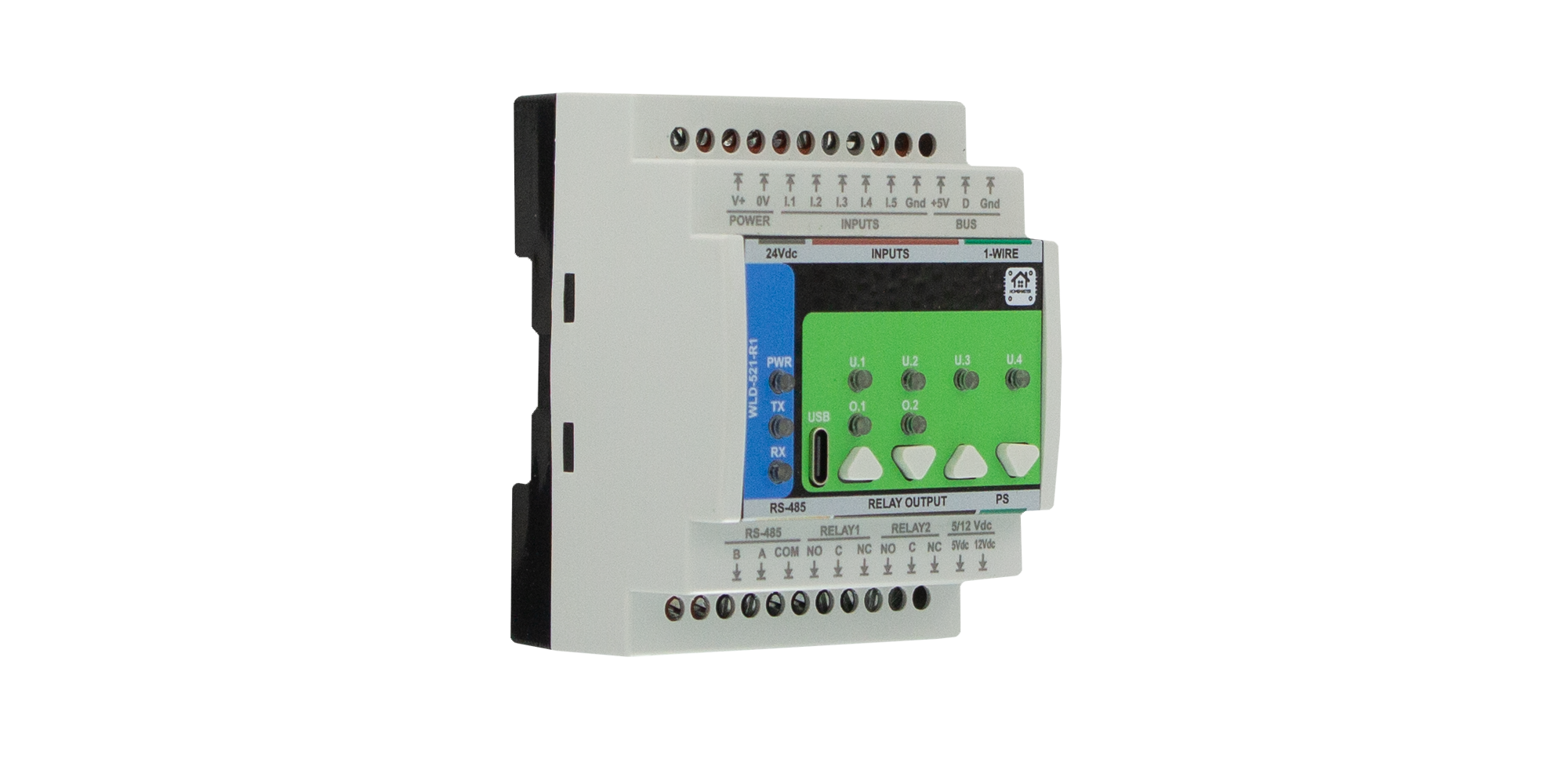
HomeMaster WLD-521-R1
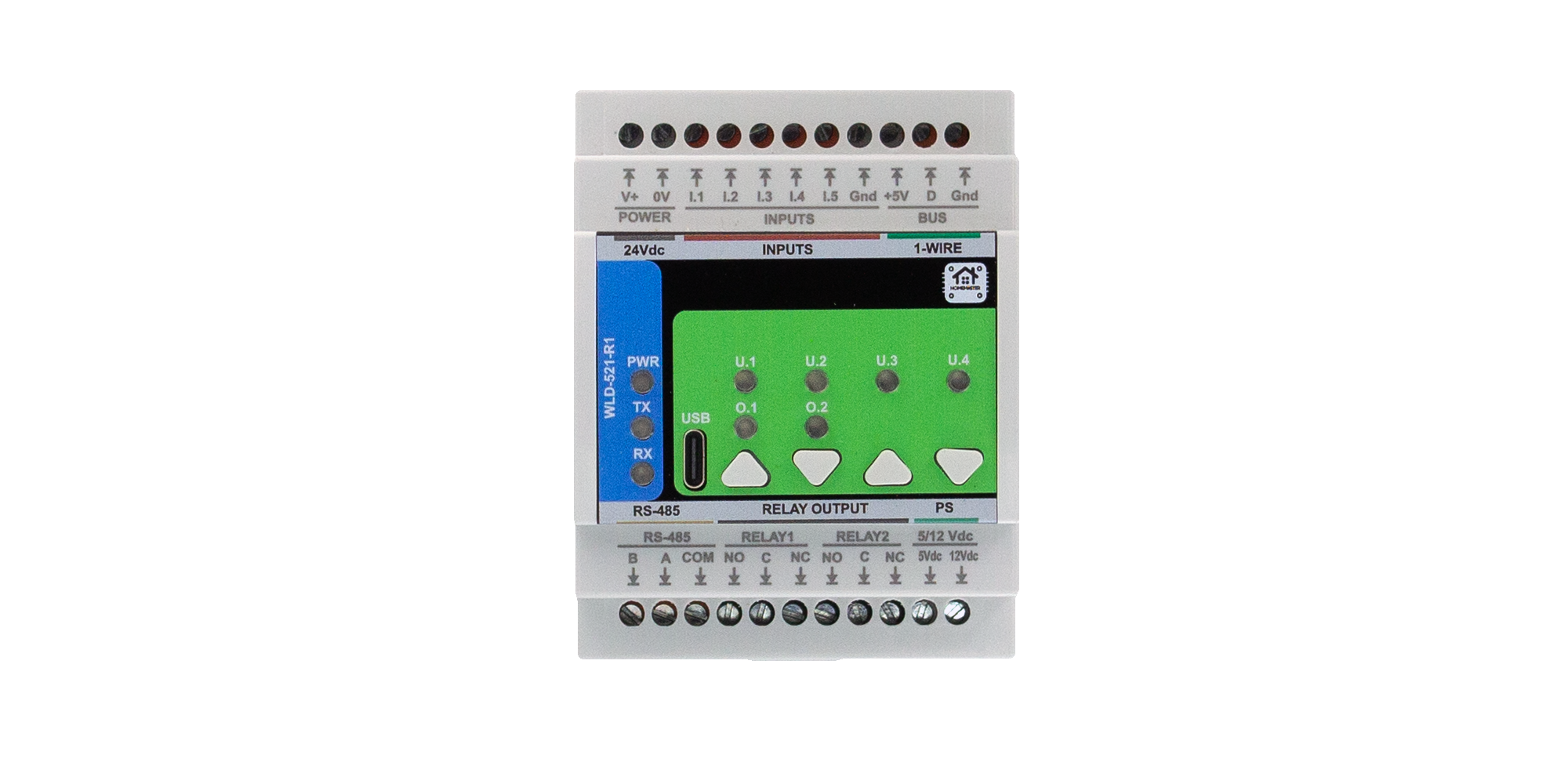
The HomeMaster WLD-521-R1 is a DIN-rail water management I/O module for leak detection, pulse water metering, optional heat energy (ΔT) monitoring, and local irrigation logic. It provides five opto-isolated digital inputs, two SPDT relay outputs, isolated sensor power rails, a protected 1-Wire bus for DS18B20 probes, RS-485 Modbus RTU, and USB-C WebConfig.
The module operates from 24 V DC and integrates with HomeMaster MicroPLC, MiniPLC, or any Modbus RTU master. Configuration is stored in onboard flash; local logic can run autonomously while I/O and telemetry remain visible to the PLC, SCADA, or Home Assistant (via ESPHome/Modbus).
Quick Overview
- Water leak, flow, irrigation, and hydronic-oriented Modbus expansion module
- DIN-rail enclosure; 24 V DC supply (V+ / 0V)
- 5 × opto-isolated digital inputs (I1–I5 + GND_ISO); configurable sensor / counter modes
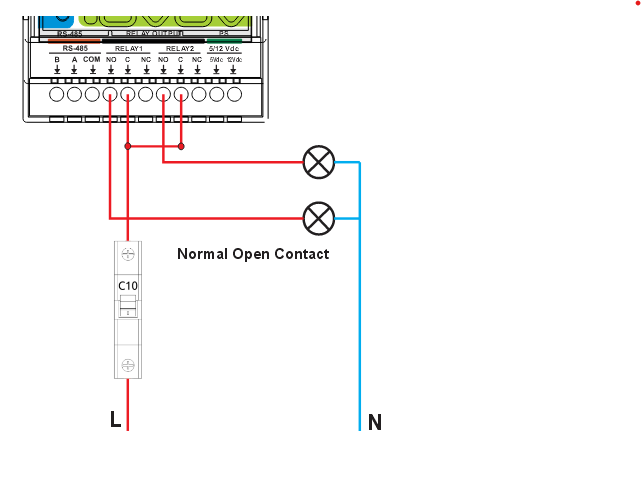
- 2 × SPDT relay outputs (NO / COM / NC); dry contacts — observe system current/voltage limits
- Isolated +5 V and +12 V sensor rails (low-power field sensors only)
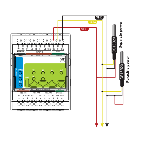
- 1-Wire interface (+5 V / DATA / GND) for temperature probes (e.g. DS18B20)
- RS-485 Modbus RTU (A / B / COM) and USB-C WebConfig
- 4 buttons and 4 user LEDs (plus power / comm / relay status LEDs)
Typical Applications
- Basement / utility leak alarms and automatic shut-off valve control
- Pulse water meters and consumption totals (litres)
- Garden or zone irrigation with flow supervision and interlocks
- Hydronic heat monitoring (flow + supply/return temperatures)
- Building water safety and BMS remote I/O
- PLC / SCADA Modbus slave node for water-related signals
- Home Assistant via ESPHome on the RS-485 master controller
Tech Specs
| Specification | Details |
|---|---|
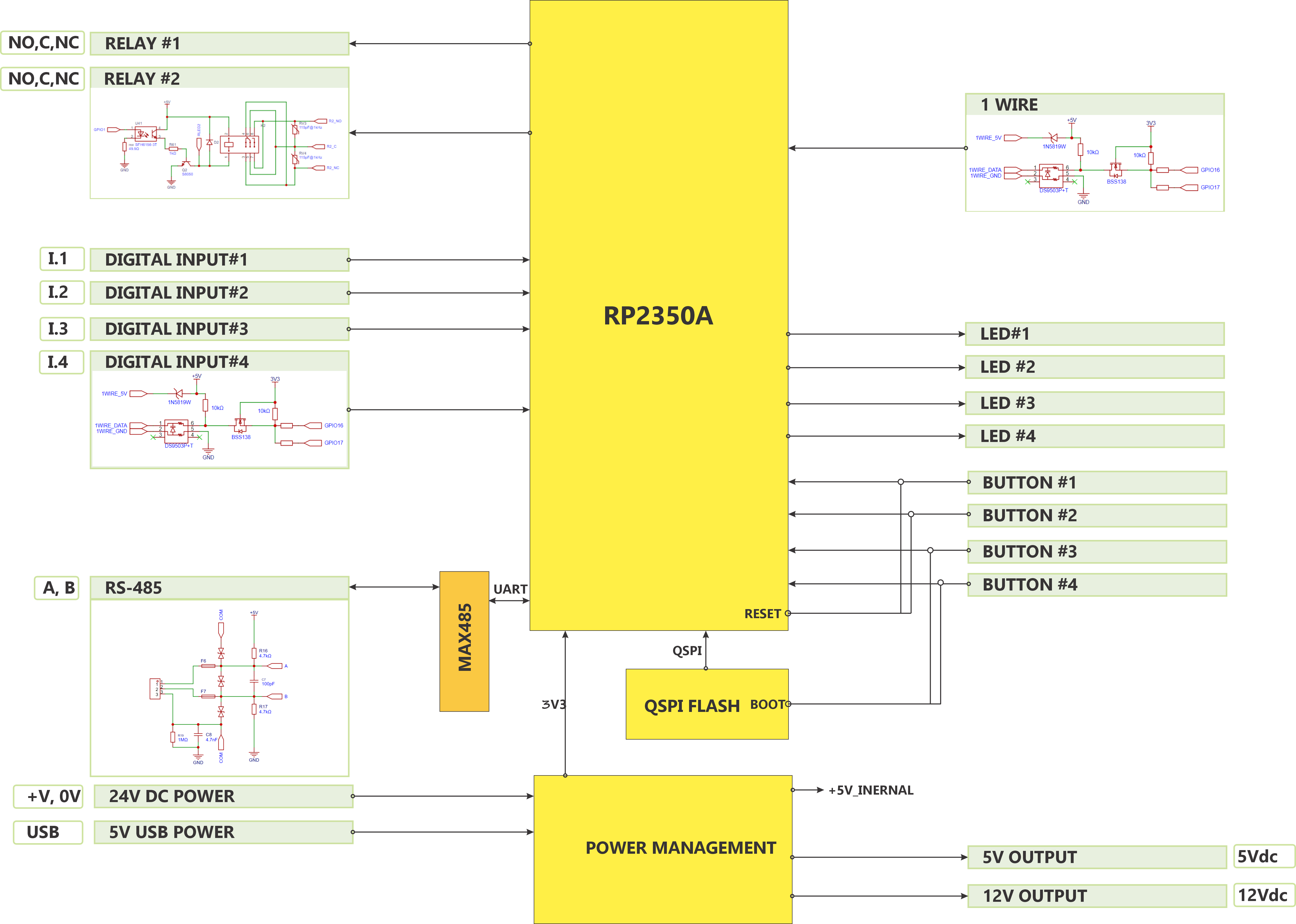
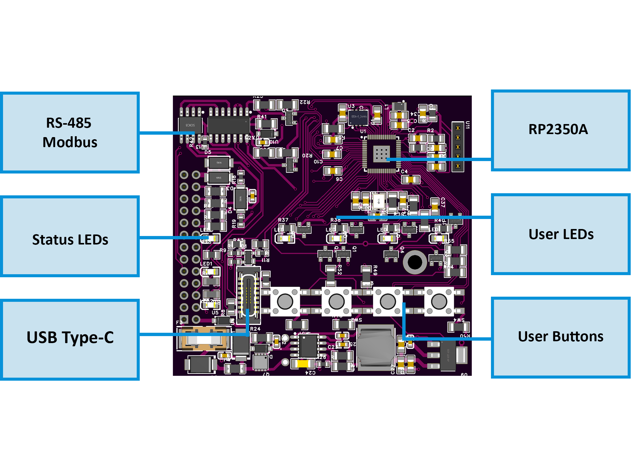
| Microcontroller | RP2350A dual-core microcontroller |
| Flash memory | External QSPI flash (W25Q32JV, 32 Mbit) |
| Power input | 24 V DC nominal (V+ / 0V); recommended range 18–30 V DC. Input protection: 1 A time-lag fuse, reverse-polarity diode, TVS, EMI filtering |
| Module power | Typical 0.2–0.5 W (logic only); maximum ≈ 3 W (relays on + isolated outputs loaded) |
| Main logic supplies | Buck 24 V → ~5 V; 3.3 V LDO |
| Digital inputs | 5 × isolated 5 V DC discrete inputs (I1–I5 + GND_ISO). Max input voltage: 5 V DC continuous (field wiring per manual) |
| Relay outputs |
2 × SPDT dry-contact relays. Rated load (system limit): 3 A @ 250 V AC (resistive); max 750 VA @ 250 V AC, 90 W @ 30 V DC. Relay components (informative only) may be rated higher; that rating does not apply to the complete module. Relay outputs are not internally fused. |
| Isolated outputs | +12 V ISO: 12 V isolated rail, 2 W; ≤150 mA recommended (≤167 mA theoretical). +5 V ISO: 5 V isolated rail, 1 W; ≤150 mA recommended (≤200 mA theoretical). For low-power sensors only — not for actuators |
| 1-Wire | 1 × protected bus (+5 V, DATA, GND) for 1-Wire sensors |
| User interface | 4 buttons; 9 LEDs (power, 4 user, RX, TX, relay 1, relay 2) |
| Communication | RS-485 half-duplex Modbus RTU; surge protection and fail-safe biasing |
| USB | USB-C, 5 V logic, ESD protected — configuration and firmware |
| Storage | LittleFS persistent configuration |
| Modbus address | 1–255 (default: 3) |
| Modbus baud rate | 9600–115200 (default: 19200), 8N1 |
Installation, Environmental & Mechanical
| Category | Specification | Details |
|---|---|---|
| Terminal specifications | Terminal type | Pluggable screw terminal blocks, 5.08 mm pitch |
| Wire cross-section | 0.2–2.5 mm² (AWG 24–12) | |
| Conductor type | Solid or stranded copper; ferrules recommended | |
| Tightening torque | 0.4–0.6 Nm | |
| Environmental ratings | Operating temperature | 0 °C to +40 °C |
| Storage temperature | −10 °C to +55 °C | |
| Relative humidity | 0–90 % RH, non-condensing | |
| Ingress protection | IP20 (inside cabinet) | |
| Maximum altitude | 2000 m | |
| Pollution degree | 2 | |
| Mechanical & packaging | Product dimensions | 71.5 × 90 × 59 mm (L × W × H) |
| DIN units | 4 division units (≈ 72 mm DIN rail mounting width) | |
| Mounting | 35 mm DIN rail (EN 50022) | |
| Enclosure | PC/ABS, UL94-V0 | |
| Net / gross weight | See product label / packing slip | |
| Pack size | 140 × 125 × 94 mm (L × W × H) | |
| Mechanical drawing | Front + side views with DIN-clip depth in the datasheet PDF |
Install only inside a control cabinet with ventilation; the cabinet must include a protective front plate covering all module connection terminals and a closing protective door; not for outdoor or exposed installation.
All wiring terminals must be protected against accidental contact by an insulating front plate, wiring duct, or terminal cover. Exposed live terminals are not permitted.

Home Assistant / Modbus / Web Config Integration
The WLD-521-R1 supports:
- HomeMaster MicroPLC and MiniPLC as Modbus masters
- PLC and SCADA via Modbus RTU
- Home Assistant using ESPHome (on the controller) or a Modbus integration
- USB-C setup with WebConfig (Chrome / Edge, Web Serial)
Configuration is saved to flash and restored at power-up.
Quick Setup (USB-C WebConfig)
- Mount & power — DIN rail; connect 24 V DC to V+ / 0V.
- USB-C — connect to the PC.
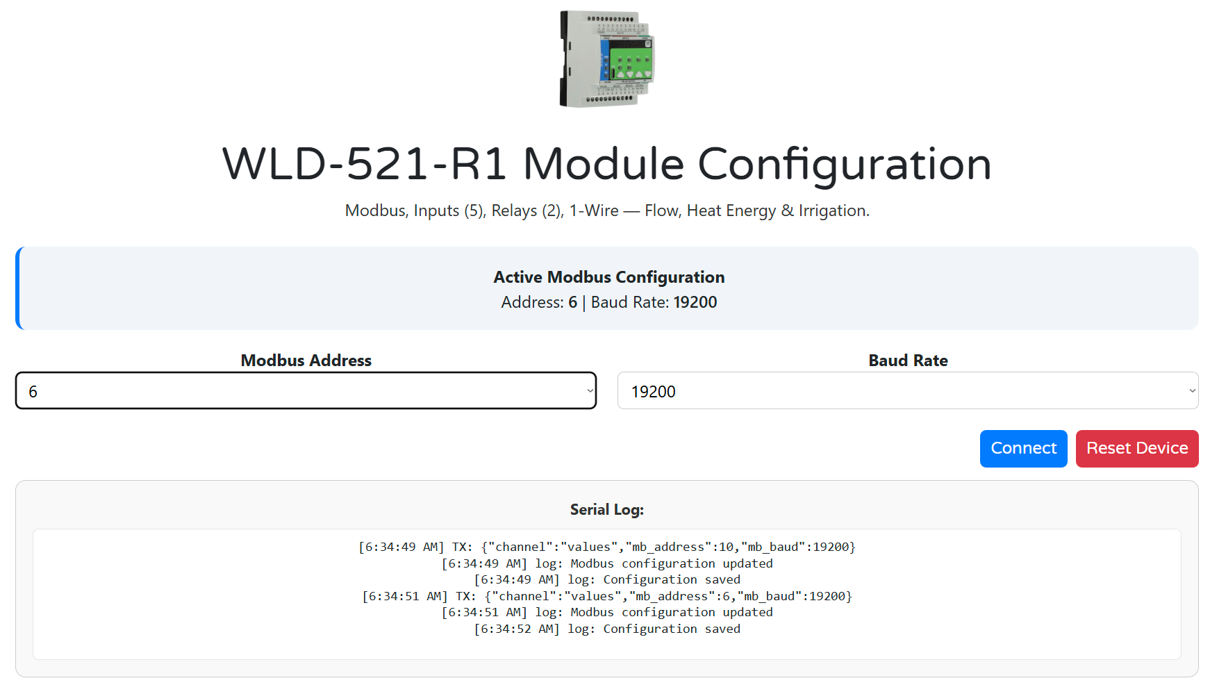
- Open WebConfig — configtool-wld-521-r1 in Chrome or Edge.
- Connect device — Connect → select the serial port.
- Modbus — set address (1–255) and baud rate (9600–115200).
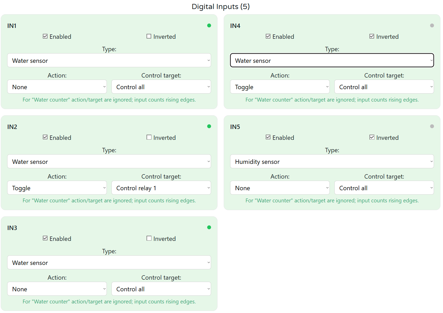
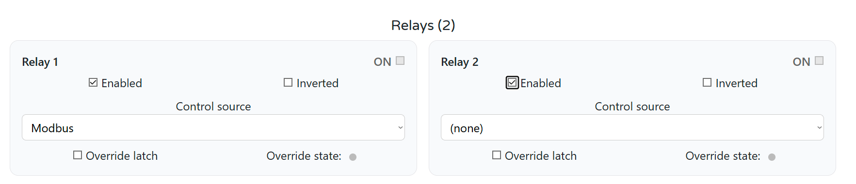
- I/O & logic — inputs (sensor / counter / heat), relays, LEDs, buttons, irrigation zones as required.
- Save — disconnect USB-C for field operation if desired.
WebConfig highlights
- Per-DI mode: water sensor, soil moisture, water counter (flow)
- Counter: pulses per litre, calibration, totals and live rate
- Optional heat: 1-Wire sensors A/B, cp, ρ, power and energy
- Relay source: Modbus, local logic, override
- LED mapping (solid/blink) and button actions
- Irrigation zones with flow supervision and time windows
Register-level detail: Modbus_Table.md and README.md.

Minimal ESPHome YAML (controller side)
Use on MiniPLC/MicroPLC (ESPHome): enables RS-485 and imports the WLD package.
uart:
id: uart_modbus
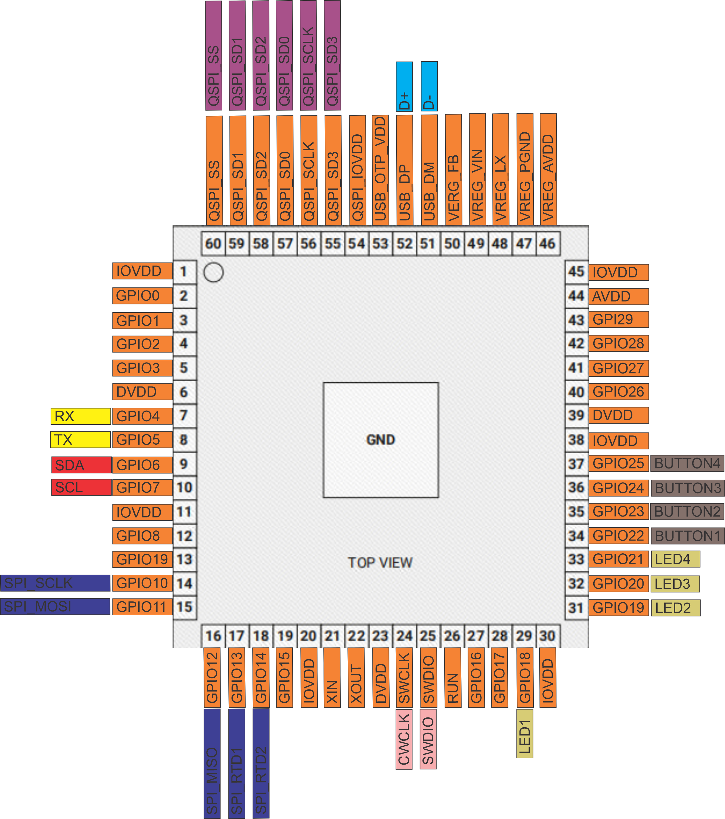
tx_pin: 17
rx_pin: 16
baud_rate: 19200
parity: NONE
stop_bits: 1
modbus:
id: modbus_bus
uart_id: uart_modbus
packages:
wld1:
url: https://github.com/isystemsautomation/HOMEMASTER
ref: main
files:
- path: WLD-521-R1/Firmware/default_wld_521_r1_plc/default_wld_521_r1_plc.yaml
vars:
wld_prefix: "WLD#1"
wld_id: wld_1
wld_address: "4"
refresh: 1d
wld_address must match the Modbus address set in WebConfig (factory default is often 3).
Documentation
The WLD-521-R1 is open-source hardware. Firmware, tools, and design files are published in the HomeMaster repository.
Hardware design files
| File | Description | Link |
|---|---|---|
| Field board schematic | Inputs, 1-Wire, isolated sensor rails | WLD-521-R1-FieldBoard.pdf |
| MCU board schematic | Controller, USB, RS-485, power conversion | WLD-521-R1-MCUBoard.pdf |
| Relay board schematic | Relay outputs and contact circuitry | WLD-521-R1-RelayBoard.pdf |
Firmware & software
| Resource | Description | Link |
|---|---|---|
| Datasheet | Official specifications, terminals, compliance summary | WLD-521-R1_Datasheet.pdf |
| Firmware & tools | Source, WebConfig page, binaries | GitHub — Firmware |
| Integration guide | Setup, Modbus, ESPHome, use cases | README.md |
| Modbus register table | Compact FC / address reference | Modbus_Table.md |
Cabling and Wirings
24 V DC supply (V+ / 0V)
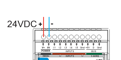
- Use a SELV 24 V DC supply within the rated input range
- Observe polarity; input is reverse-polarity protected
- Size the supply for module + relay coils + modest sensor rail load
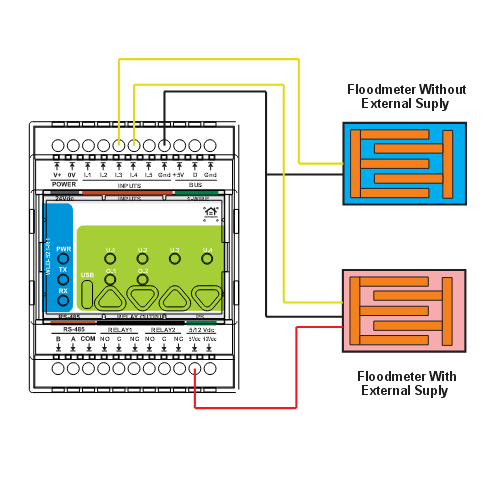
Digital inputs (leak / moisture / contacts)
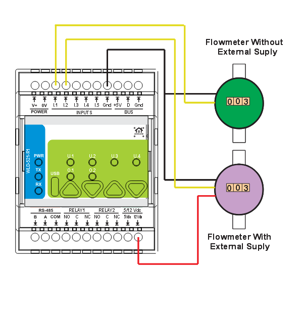
Pulse flow meter (counter mode)
1-Wire temperature sensors
Relay outputs (NO / COM / NC)
External protection required: each load shall be protected by a suitable fuse or breaker. Relay contacts are not internally fused. Relay terminals may switch hazardous voltage — install per applicable electrical codes.
RS-485 Modbus (A / B / COM)
| Terminal | Function |
|---|---|
| A | RS-485 A |
| B | RS-485 B |
| COM | RS-485 common / reference |
- Daisy-chain topology; keep stubs short
- Match A/B polarity across the bus
- Terminate with 120 Ω at the two physical ends of the segment
- Connect COM between nodes for a stable reference (per installation design)
Cable Recommendations & Shield Grounding
Use shielded, twisted constructions and bond shields correctly to reduce EMI and ground-loop issues (per datasheet).
General routing rules
- Route low-level signal cables separately from power and relay load wiring
- If crossing power cables is unavoidable, cross at 90°
- Keep runs short; avoid long parallel routing with high-current conductors
- Label cables and provide strain relief at terminals
Digital inputs & sensor cables
- Twisted pair from each sensor to the corresponding Ix and return
- Wire size compatible with 5.08 mm terminals (e.g. 0.2–2.5 mm²)
- In noisy panels, prefer shielded cable; terminate shields per the shielding section below — not to signal terminals
RS-485 (Modbus) cable
- Twisted pair for A/B; characteristic impedance ~120 Ω recommended
- Shielded cable recommended in industrial environments
- Second conductor or pair for COM reference where required by the network design
Shield grounding
- Bond cable shield(s) to cabinet PE/EMC ground at one end (PLC/controller side typical)
- Do not connect shields directly to A, B, or COM signal terminals
- Keep shield pigtails short and low-inductance
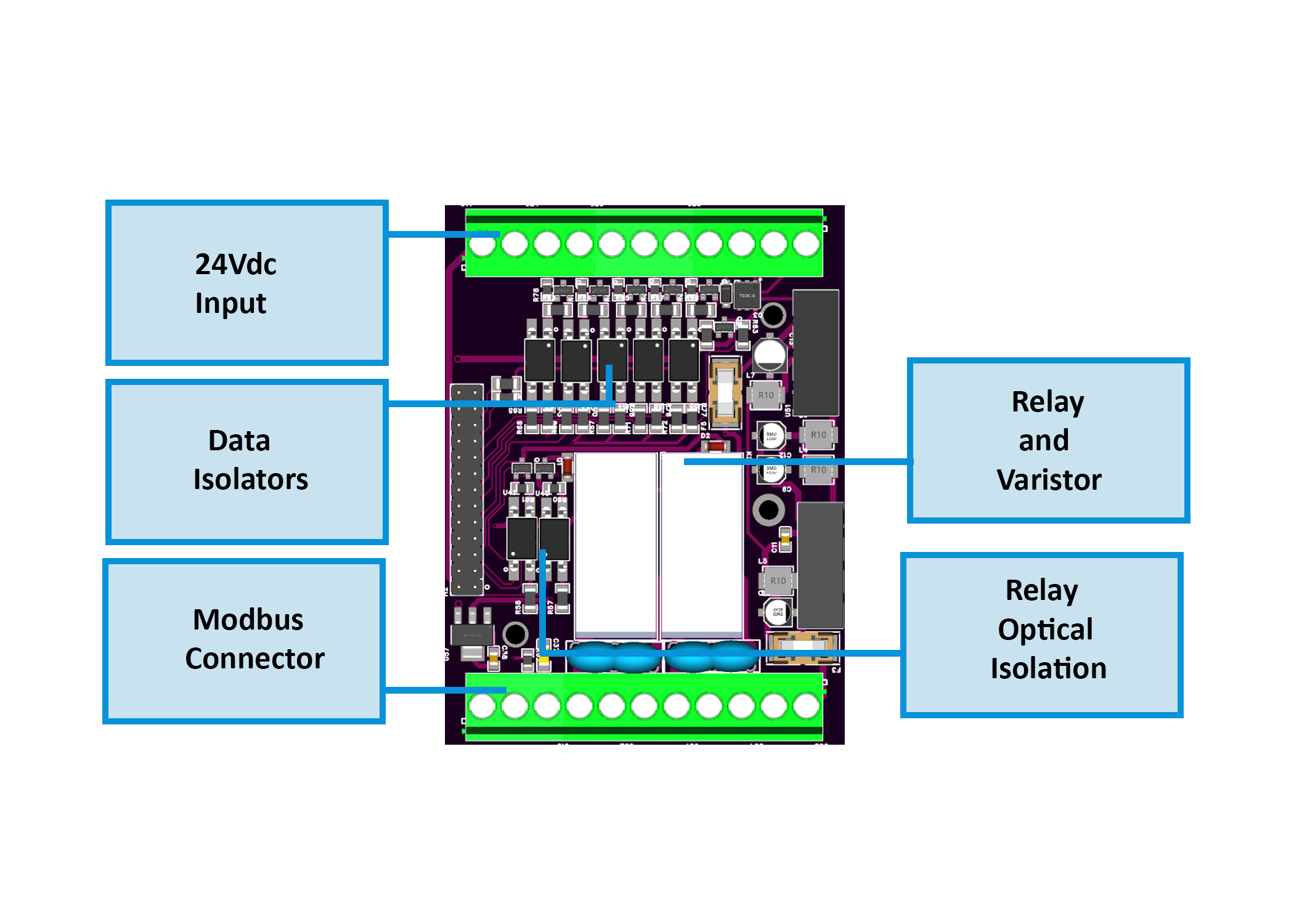
System Architecture & Pinout
Safety and Installation Notes
- SELV on power and signal terminals as defined in the datasheet; relay contacts may switch up to 250 V AC — observe separation, insulation, and local electrical codes
- Installation by qualified personnel only
- Indoor control cabinet; IP20; protect all terminals from accidental touch
- Respect the 3 A / 750 VA / 90 W system limits for relay loads; use contactors for higher currents or demanding inductive loads
- Provide external fuses or breakers for every switched load; snubbers or suppression for inductive DC/AC loads where required
- Do not power valves, pumps, or heavy actuators from +5 V ISO / +12 V ISO — sensors only, within current limits
- Do not exceed 5 V DC on digital inputs (datasheet continuous maximum)
- USB-C is intended for configuration/diagnostics — not a field power input
Compliance & Certifications
The WLD-521-R1 is CE marked and designed to comply with applicable European Union directives. ISYSTEMS AUTOMATION S.R.L. (HomeMaster) maintains technical documentation and a signed EU Declaration of Conformity (DoC).
EU directives
EMC 2014/30/EU · LVD 2014/35/EU · RoHS 2011/65/EU
Standards (datasheet)
| Area | Standards |
|---|---|
| EMC | EN 61000-6-1 · EN 61000-6-3 |
| Electrical safety | EN 62368-1 |
| RoHS | EN IEC 63000 |
Equipment classification
Industrial / commercial control equipment — install only in the intended environment and enclosure class.
Safety notice
Power input and signal-level circuits are SELV. Relay outputs may switch hazardous voltages — qualified installation only. See the datasheet PDF for the full conformity statement and manufacturer contact.
Related products
These other products might interest you