


ENM-223-R1 3-Phase Power Quality & Energy Metering Module
The ENM-223-R1 is an advanced three-phase energy monitoring and automation module designed for real-time measurement, protection logic and automated power control. It measures voltage, current, power, frequency and energy consumption per phase while offering built-in relays, alarm logic, and data reporting through Modbus RTU.
Designed for seamless integration with HomeMaster MiniPLC and MicroPLC controllers, this energy meter is ideal for smart homes, solar systems, industrial installations, and power-sensitive environments.
Display Name:
ENM-223-R1 3-Phase Power Quality & Energy Metering Module
ENM-223-R1 — 3‑Phase Power Metering & I/O Module
Firmware Version: 2025-09 snapshot
ENM-223-R1 — 3-Phase Power Metering & I/O Module
HOMEMASTER – Modular control. Custom logic.
Module Description
The ENM-223-R1 is a configurable smart I/O module designed for 3-phase power quality and energy metering.
It includes 3 voltage inputs, 3 current channels, 2 relays, and optional 4 buttons / 4 LEDs, with configuration via WebConfig using USB-C (Web Serial).
It connects over RS-485 (Modbus RTU) to a MicroPLC/MiniPLC, enabling use in energy monitoring, automation, and smart building applications.
Table of Contents
- 1. Introduction
- 2. Use Cases
- 3. Safety Information
- 4. Installation & Quick Start
- 5. MODULE-CODE — Technical Specification
- 6. Modbus RTU Communication
- 7. ESPHome Integration Guide (if applicable)
- 8. Programming & Customization
- 9. Maintenance & Troubleshooting
- 10. Open Source & Licensing
- 11. Downloads
- 12. Support
1. Introduction
1.1 Overview of the ENM‑223‑R1 Module ⚡
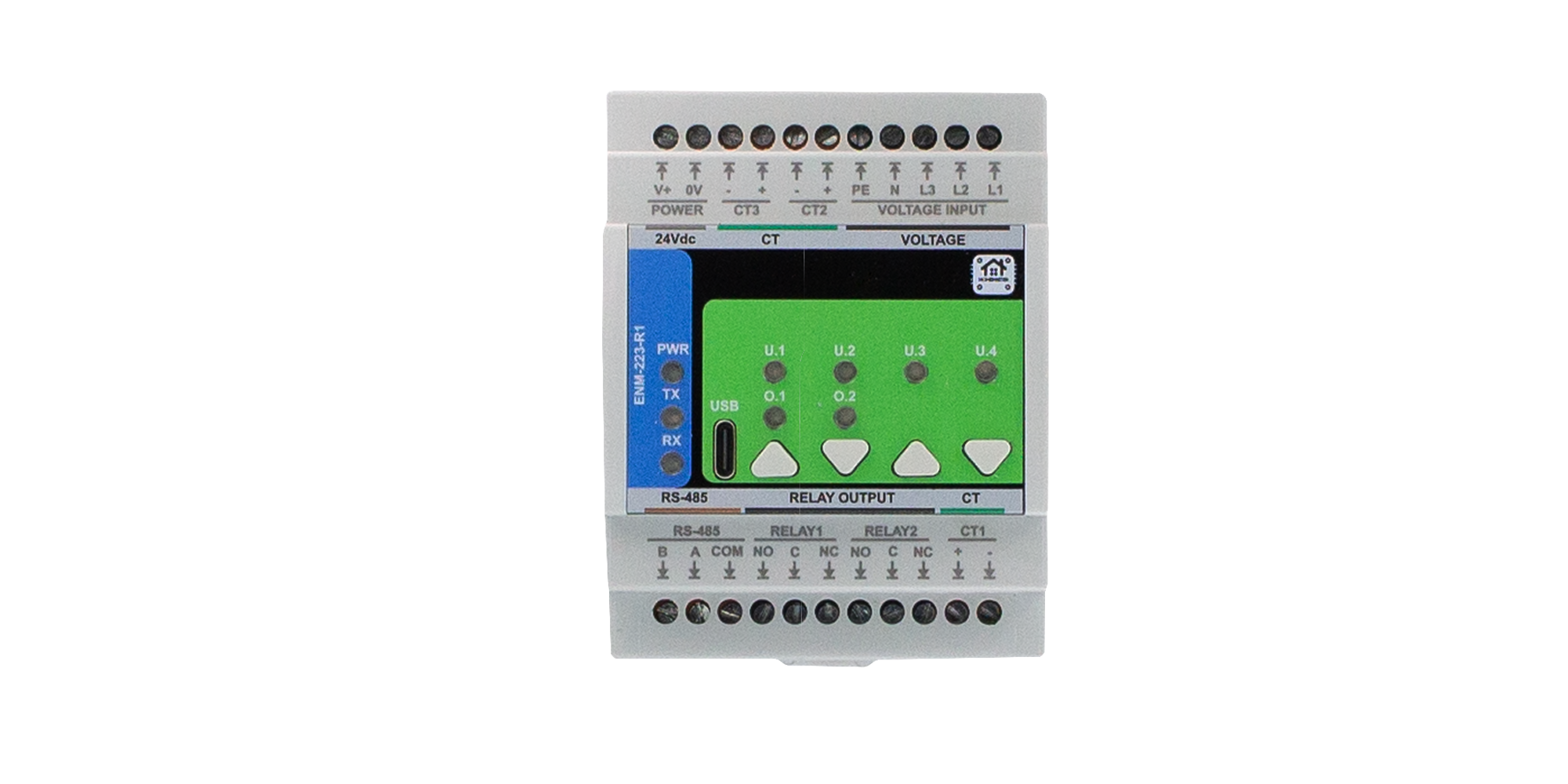
The ENM‑223‑R1 is a modular 3‑phase energy metering + I/O device for power monitoring, automation, and local control. It features 3 voltage channels (L1/L2/L3‑N), 3 current channels (external CTs), 2 SPDT relays, 4 user LEDs, and 4 buttons—all driven by an RP2350 MCU with QSPI flash and a dedicated ATM90E32AS metering IC.
It integrates with MiniPLC/MicroPLC controllers or any Modbus RTU master over RS‑485, and it’s configured in‑browser via USB‑C Web Serial (no drivers). Typical uses include energy dashboards, demand response, alarm‑driven relay control, and building automation. Defaults ship as Modbus address 3 @ 19200 8N1 (changeable in WebConfig).
Quick device flow:
Wire Lx/N/PE + CTs → set address/baud in WebConfig → calibrate gains/offsets → define alarms per L1/L2/L3/Totals → map relays/LEDs/buttons → connect RS‑485 A/B (and GND if separate PSUs) → poll via Modbus.
1.2 Features & Architecture
Core Capabilities
| Subsystem | Qty | Description |
|---|---|---|
| Voltage Inputs | 3 | L1/L2/L3‑N measurement (divider network on FieldBoard) feeding ATM90E32AS |
| Current Inputs | 3 | Differential CT inputs (IAP/IAN, IBP/IBN, ICP/ICN) with filtering/burdens |
| Relays | 2 | SPDT dry contacts (NO/NC); opto‑driven; alarm‑ or Modbus‑controlled |
| LEDs | 4 | User LEDs; sources: overrides/alarms/warnings/events; steady or blink |
| Buttons | 4 | User actions (toggle relays/LEDs, overrides, acks) with live state feedback |
| Metering & Energy | — | ATM90E32AS: Urms/Irms, P/Q/S, PF, angle, freq; energy kWh/kvarh/kVAh (phase & totals) |
| Config UI | Web Serial | In‑browser WebConfig over USB‑C (Chrome/Edge); live meter, calibration, alarms, relays, LEDs, buttons |
| Modbus RTU | RS‑485 | Multi‑drop slave; address 1…255; baud 9600–115200 (default 19200 8N1) |
| MCU | RP2350 + QSPI | Dual‑core MCU, native USB, external W25Q32 flash; RS‑485 via MAX485 transceiver |
| Power | 24 VDC | Buck to 5 V → 3.3 V LDO; isolated analog domain via B0505S DC‑DC + ISO7761 |
| Protection | TVS, PTC, fuses | Surge/ESD on USB & RS‑485; resettable fuses on field I/O; reverse‑polarity protection |
1.3 System Role & Communication 🍰
The ENM‑223‑R1 is a smart Modbus RTU slave. It executes local alarm logic (thresholds & acks) and mirrors states/values to a PLC or SCADA via registers/coils. Configuration (meter options, calibration, relay/LED logic, button actions, Modbus address/baud) is done via USB‑C WebConfig, stored to non‑volatile memory.
| Role | Description |
|---|---|
| System Position | Expansion meter+I/O on the RS‑485 trunk (A/B/GND) |
| Master Controller | MiniPLC / MicroPLC or any third‑party Modbus RTU master (polling) |
| Address / Baud | Configurable 1…255 / 9600–115200; factory default: ID 3 @ 19200 8N1 |
| Bus Type | RS‑485 half‑duplex; termination/bias per bus rules; share GND if separate PSUs |
| USB‑C Port | Setup/diagnostics via Chromium browser (Web Serial); native USB D+/D− to MCU |
| Default Modbus ID | 3 (change in WebConfig) |
| Daisy‑Chaining | Multi‑drop on shared A/B; ensure unique IDs and end‑of‑line termination |
Note: The UI exposes per‑channel Alarm / Warning / Event with min/max thresholds and Ack required option; relays can follow selected alarm kinds or be Modbus‑controlled. Buttons can toggle/override relays; LEDs reflect overrides or alarm states.
2. Use Cases
This section outlines practical application examples for the ENM‑223‑R1 module. Each use case includes a functional goal and a clear configuration procedure using the WebConfig tool and/or Modbus RTU integration.
These templates are applicable in energy management, automation, industrial control, and building infrastructure deployments.
2.1 Overcurrent Alarm with Manual Reset
Purpose: Activate Relay 1 when current exceeds a configured threshold and hold it until manually acknowledged.
Configuration:
- Alarms → Channel:
Totals- Enable Alarm
- Metric:
Current (Irms) - Max threshold: e.g.
> 5000(for 5 A) - Enable Ack required
- Relays → Relay 1
- Mode:
Alarm Controlled - Channel:
Totals, Kinds:Alarm
- Mode:
- LEDs → LED 1
- Source:
Alarm Totals, Mode:Steady
- Source:
- Acknowledge: via Web UI, Modbus coils
610–613, or front panel button (if assigned)
2.2 Manual Override for Load Control
Purpose: Allow field operators to override Relay 2 using a button, regardless of Modbus or automation control.
Configuration:
- Relays → Relay 2
- Mode:
Modbus Controlled - Enabled at power-on
- Mode:
- Buttons → Button 2
- Action:
Override Relay 2 (hold 3s)
- Action:
- LEDs → LED 2
- Source:
Override R2, Mode:BlinkorSteady
- Source:
Holding the button for 3 seconds enters override mode. A short press toggles the relay. Holding again exits override mode.
2.3 Environmental Voltage/Frequency Alarm with Auto-Clear
Purpose: Detect power quality faults (sag/swell or freq drift), activate Relay 1 as an output, and auto-reset when back in range.
Configuration:
- Alarms → Channel:
L1- Enable Alarm
- Metric:
Voltage (Urms) - Min:
21000(210 V), Max:25000(250 V) - Leave Ack required unchecked
- Relays → Relay 1
- Mode:
Alarm Controlled, Channel:L1, Kinds:Alarm
- Mode:
- LEDs → LED 1
- Source:
Alarm L1
- Source:
2.4 Staged Load Shedding via Modbus Scenes
Purpose: Use a controller to shed non-critical loads as power consumption increases.
Configuration:
- Relays → Relay 1 and Relay 2
- Mode:
Modbus Controlled
- Mode:
- In PLC logic:
- Monitor
Totals S (VA)via Input Register - If
S > 8000, write coil600 = OFF(Relay 1) - If
S > 10000, write coil601 = OFF(Relay 2) - Restore relays when values drop below defined hysteresis limits
- Monitor
Ideal for HVAC or lighting where priority-based power shedding is needed.
Summary Table
| Use Case | Feature Used | Reset Method | Relay Mode |
|---|---|---|---|
| Overcurrent Alarm + Ack | Alarms, Ack, Relay 1 | Manual (Ack) | Alarm Controlled |
| Manual Override via Button | Button override, LED | Button toggle | Modbus Controlled |
| Voltage/Frequency Fault Auto-Reset | Alarm (no ack), Relay | Auto (value returns) | Alarm Controlled |
| Load Shedding (Staged Scenes) | PLC Modbus, Relay 1 & 2 | PLC-controlled | Modbus Controlled |
🛠 All parameters are configurable via USB‑C WebConfig. Modbus control assumes master-side logic (PLC, SCADA, or MicroPLC/MiniPLC).
3. Safety Information
These safety guidelines apply to the ENM‑223‑R1 3‑phase metering and I/O module. Ignoring them may result in equipment damage, system failure, or personal injury.
⚠️ Mixed Voltage Domains — This device contains both SELV (e.g., 24 V DC, RS‑485, USB) and non-SELV mains inputs (85–265 V AC). Proper isolation, wiring, and grounding are required. Never connect SELV and mains GND together.
3.1 General Requirements
| Requirement | Detail |
|---|---|
| Qualified Personnel | Installation and servicing must be done by qualified personnel familiar with high-voltage and SELV control systems. |
| Power Isolation | Disconnect both 24 V DC and voltage inputs (Lx/N) before servicing. Use lockout/tagout where applicable. |
| Environmental Limits | Mount in a clean, sealed enclosure. Avoid condensation, conductive dust, or vibration. |
| Grounding | Bond the panel to PE. Wire PE and N to the module. Never bridge GND_ISO to logic GND. |
| Voltage Compliance | CT inputs: 1 V or 333 mV RMS only. Voltage inputs: 85–265 V AC. Use upstream fusing and surge protection. |
3.2 Installation Practices
| Task | Guidance |
|---|---|
| ESD Protection | Handle only by the case. Use antistatic wrist strap and surface when the board is exposed. |
| DIN Rail Mounting | Mount securely on 35 mm DIN rail inside an IP-rated cabinet. Allow cable slack for strain relief. |
| Wiring | Use correct gauge wire and torque terminal screws. Separate relay, CT, and RS‑485 wiring. |
| Isolation Domains | Respect isolation: Do not bridge GND_ISO to GND. Keep analog and logic grounds isolated. |
| Commissioning | Before power-up, verify voltage wiring, CT polarity, RS‑485 A/B orientation, and relay COM/NO/NC routing. |
3.3 I/O & Interface Warnings
⚡ Power
| Area | Warning |
|---|---|
| 24 V DC Input | Use a clean, fused SELV power source. Reverse polarity is protected but may disable the module. |
| Voltage Input | Connect L1/L2/L3/N/PE only within rated range (85–265 V AC). Use circuit protection upstream. |
| Sensor Domain | Use CTs with 1 V or 333 mV RMS output. Never apply 5 A directly. Observe polarity and shielding. |
🧲 Inputs & Relays
| Area | Warning |
|---|---|
| CT Inputs | Accept only voltage-output CTs. Reversing polarity may affect power sign. Use GND_ISO reference. |
| Relay Outputs | Dry contacts only. Rated: 5 A @ 250 VAC or 30 VDC. Use snubber (RC/TVS) for inductive loads. |
🖧 Communication & USB
| Area | Warning |
|---|---|
| RS‑485 Bus | Use twisted pair. Terminate at both ends. Match A/B polarity. Share GND if powered from different PSUs. |
| USB-C (Front) | For setup only. Not for permanent field connection. Disconnect during storms or long idle periods. |
🎛 Front Panel
| Area | Warning |
|---|---|
| Buttons & LEDs | Can override relays or trigger alarms. Use firmware settings or lockout for safety-critical installs. |
🛡 Shielding & EMC
| Area | Recommendation |
|---|---|
| Cable Shields | Terminate at one side only (preferably PLC/controller). Route away from VFDs and high-voltage cabling. |
✅ Pre‑Power Checklist
- All wiring is torqued, labeled, and strain-relieved
- No bridge between logic GND and GND_ISO
- PE and N are wired to terminals
- RS‑485 A/B polarity and 120 Ω termination confirmed
- Relay loads do not exceed 5 A or contact voltage rating
- CTs installed with correct polarity and securely landed
- Voltage inputs fused, protected, and within spec (85–265 V AC)
🧷 Tip: In single-phase installations, energize L1 and tie L2/L3 → N to prevent phantom voltages.
4. Installation & Quick Start
The ENM‑223‑R1 connects to your system over RS‑485 (Modbus RTU) and supports configuration via USB‑C WebConfig. Setup involves:
1) Physical wiring, 2) Digital setup (WebConfig → Modbus or PLC/ESPHome control).
4.1 What You Need
| Category | Item / Notes |
|---|---|
| Hardware | ENM‑223‑R1 module: DIN-rail, 3 voltage channels, 3 CTs, 2 relays, 4 buttons, 4 LEDs, RS‑485, USB‑C |
| Controller | MicroPLC, MiniPLC, or any Modbus RTU master |
| 24 VDC Power (SELV) | Regulated 24 V DC @ ~100–200 mA |
| RS‑485 Cable | Twisted pair for A/B + COM/GND; external 120 Ω end-termination |
| USB‑C Cable | For WebConfig setup via Chromium browser (Chrome/Edge) |
| Software | Web browser (Web Serial enabled), ConfigToolPage.html |
| Field Wiring | L1/L2/L3/N/PE → voltage inputs, CT1/2/3 → external CTs |
| Load Wiring | Relay outputs (NO/COM/NC); observe relay max rating and use snubbers on inductive loads |
| Isolation Domains | GND (logic) ≠ GND_ISO (metering); never bond these directly |
| Tools | Torque screwdriver, ferrules, USB-capable PC, 120 Ω terminators if needed |
Quick Path
① Mount → ② wire 24 VDC + RS‑485 (A/B/COM) → ③ connect USB‑C → ④ launch WebConfig →
Set Address/Baud → assign Inputs/Relays/LEDs → confirm data → ⑤ disconnect USB → hand control to Modbus master.
4.2 Power
The ENM‑223‑R1 uses 24 V DC input for its interface domain and internally isolates metering circuits.
- Power Terminals: Top left:
V+and0V - Voltage Range: 22–28 V DC (nominal 24 V)
- Typical Current: 50–150 mA (relays off/on)
- Protection: Internally fused, reverse-polarity protected
- Logic domain: Powers MCU, RS‑485, LEDs, buttons, relays
4.2.1 Sensor Isolation
- Metering IC (ATM90E32AS) is powered from an isolated 5 V rail
- Analog domain uses GND_ISO, fully isolated from GND
- Do not connect GND_ISO ↔ GND; isolation via B0505S + ISO7761
Only voltage inputs (Lx-N) and CTs connect to the isolated domain.
4.2.2 Power Tips
- Do not power relays or outputs from metering-side inputs
- Use separate fusing on L1–L3
- Tie L2, L3 → N if using single-phase only (prevents phantom voltage)
- Confirm PE is wired — improves stability & safety
4.3 Networking & Communication
4.3.1 RS‑485 (Modbus RTU)
Physical
| Terminals | Description |
|---|---|
A, B |
Differential signal pair (twisted/shielded) |
COM/GND |
Logic reference (tie GNDs if on separate supplies) |
Cable & Topology
- Twisted pair (with or without shield)
- Terminate with 120 Ω at each bus end (not inside module)
- Biasing resistors (pull-up/down) should be on the master
Defaults
| Setting | Value |
|---|---|
| Modbus Address | 3 |
| Baud Rate | 19200 |
| Format | 8N1 |
| Address Range | 1–247 |
🧷 Reversed A/B will cause CRC errors — check if no response.
4.3.2 USB‑C (WebConfig)
Purpose: Web-based configuration tool over native USB Serial. Supports:
- Live readings
- Address/baudrate config
- Phase mapping
- Relay/button/LED logic
- Alarm setup
- Calibration (gains/offsets)
Steps
- Connect USB‑C to PC (Chrome/Edge)
- Open
tools/ConfigToolPage.html - Click Connect, select ENM serial port
- Configure settings: address, relays, LEDs, alarms, calibration
- Click Save & Disconnect when finished
⚠️ If Connect is greyed out: check browser support, OS permissions, and close any other apps using the port.
4.4 Installation & Wiring
Use diagrams and explain:
- Inputs
- Relays
- Sensor rails (12/5V)
- RS-485 terminals
- USB port
4.5 Software & UI Configuration
The ENM‑223‑R1 is configured using the browser‑based WebConfig Tool
(tools/ConfigToolPage.html) over USB‑C.
No drivers or software installation is required — configuration happens directly via Web Serial API (Chrome/Edge).
- WebConfig refreshes live data every 1 s.
- Click into a field to pause refresh for that field.
- Press Enter to apply a change.
- All settings are stored in non‑volatile flash.
1) Modbus Setup (Address & Baud)
- Click Connect and select the USB serial port.
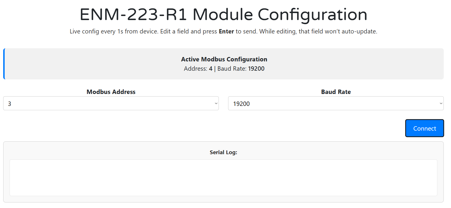
- The Active Modbus Configuration bar shows the current Address and Baud Rate.
- You can configure:
- Modbus Address:
1–255(default =3) - Baud Rate:
9600 / 19200 / 38400 / 57600 / 115200(default =19200)
- Modbus Address:
- Changes are live and applied on selection.
- If you change baud or address, remember to reconnect the controller with updated settings.
2) Meter Options & Calibration
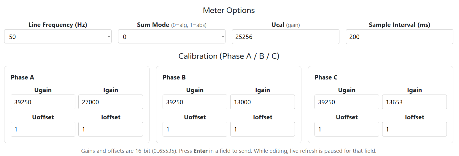
Meter Options
- Line Frequency: 50 / 60 Hz (affects metering IC behavior)
- Sum Mode:
0 = algorithmic(P = P1 + P2 + P3)1 = absolute(P = |P1| + |P2| + |P3|)
- Ucal (gain): global voltage scaling multiplier
- Sample Interval (ms): rate at which readings update (10–5000 ms)
Calibration (per phase A/B/C)
- Ugain / Igain: scaling gains (16-bit, 0–65535)
- Uoffset / Ioffset: calibration offsets (signed)
- Press Enter after editing to write the value to the module.
3) Alarms / Inputs (Per‑Channel Rules)
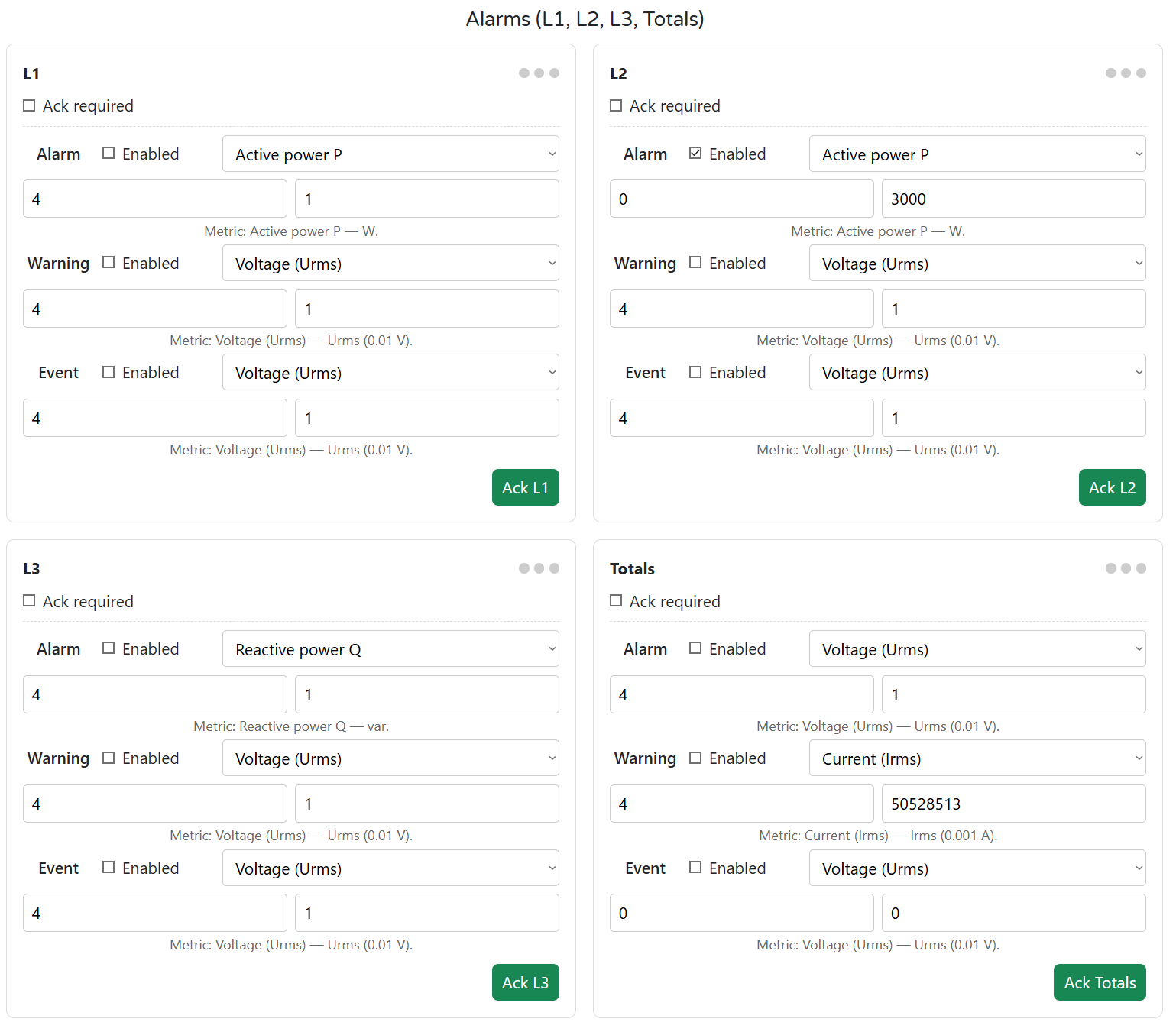
The ENM has 4 measurement channels: L1, L2, L3, and Totals.
Each channel supports:
- 3 rule slots: Alarm, Warning, Event
- Metric types:
- Voltage (Urms)
- Current (Irms)
- Active Power P
- Reactive Power Q
- Apparent Power S
- Frequency
You can configure:
- Enable toggle
- Metric, Min, and Max thresholds
- Ack required — latches the Alarm state until acknowledged
Acknowledgment:
- Press Ack L1–L3 / Totals in UI
- Or write to Modbus coil (
610–613)
💡 ENM has no digital inputs (DIs). These rules are “virtual inputs” based on real-time metering data.
4) Relay Logic Modes
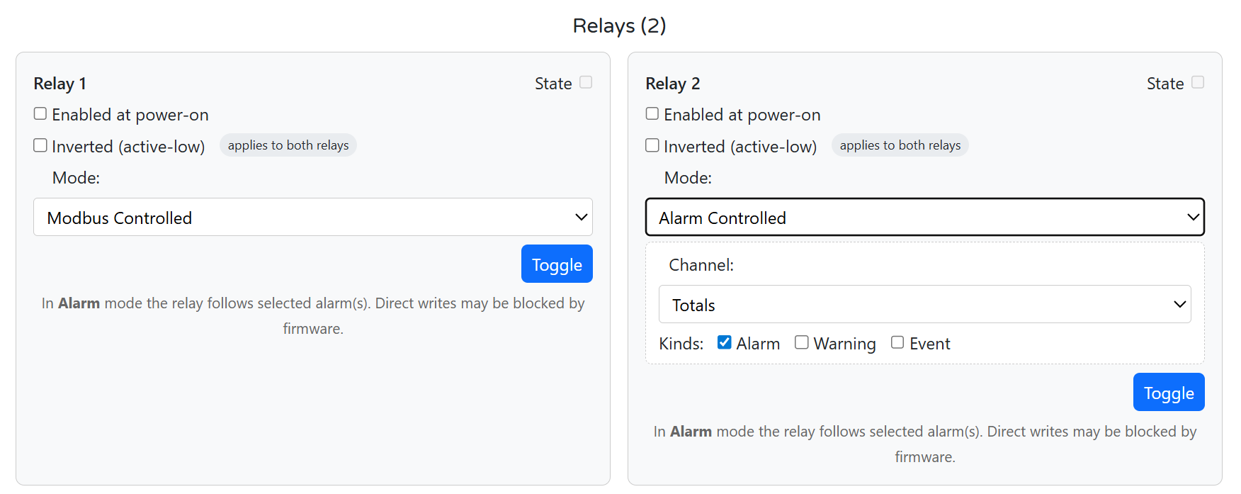
Each of the two onboard SPDT relays can be configured independently.
Options:
| Setting | Description |
|---|---|
| Enabled at Power-On | Relay state after boot (on/off) |
| Inverted (active-low) | Affects both relays; sets low = ON |
| Mode | None, Modbus Controlled, or Alarm Controlled |
| Toggle | Manually toggle the relay from the UI |
| Alarm Control Options | Select Channel: L1–L3 or Totals and which kinds to follow: Alarm / Warning / Event |
In Alarm Controlled mode, direct Modbus writes may be blocked when an alarm is active.
5) Button & LED Mapping
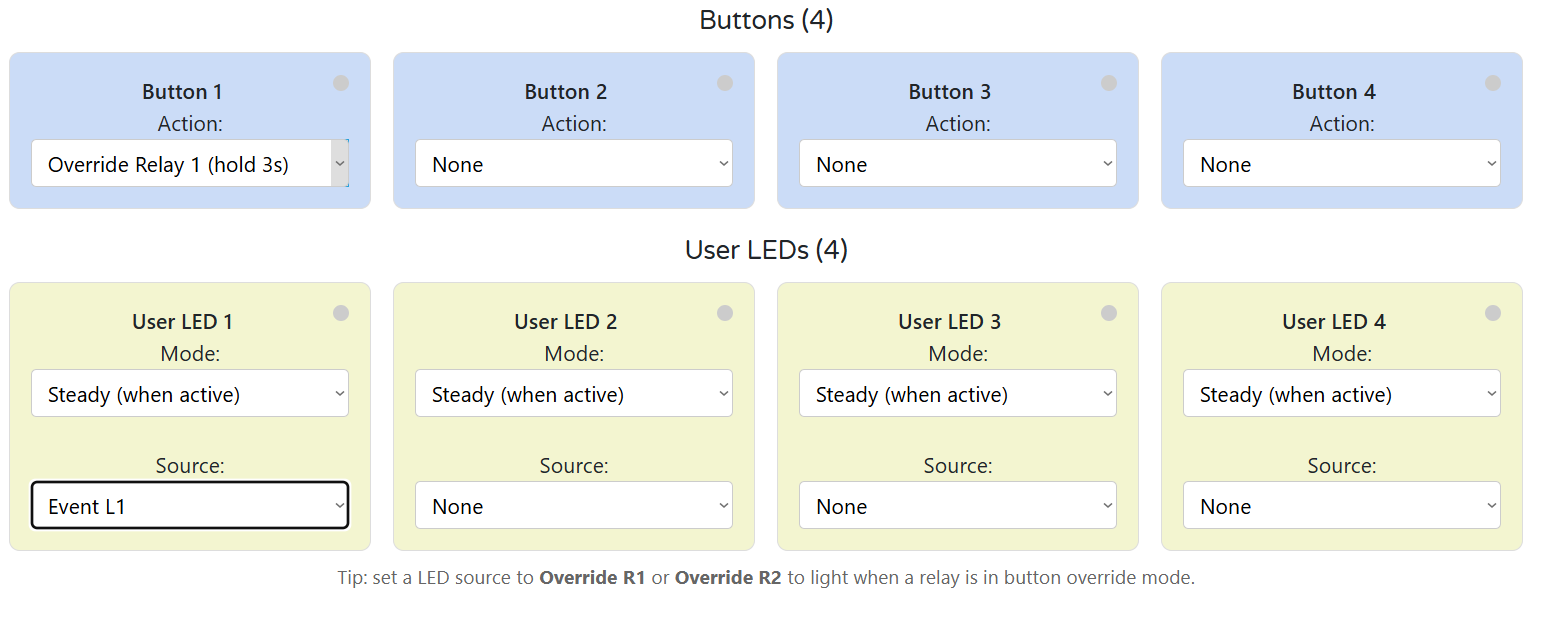
Buttons (1–4)
Each button can be mapped to:
NoneToggle Relay 1/2Toggle LED 1–4Override Relay 1/2 (hold 3s)- Hold 3 s to enter override
- Short press toggles the relay
- Hold again to exit override
User LEDs (1–4)
Each LED has:
- Mode:
Steady (when active)orBlink (when active) - Source:
Override R1/R2- Alarm, Warning, Event — for any channel
Any (A|W|E)— a combined indicator per channel
💡 Use
Override R1as LED 1 source to give a clear local override status.
6) Live Meter & Energies
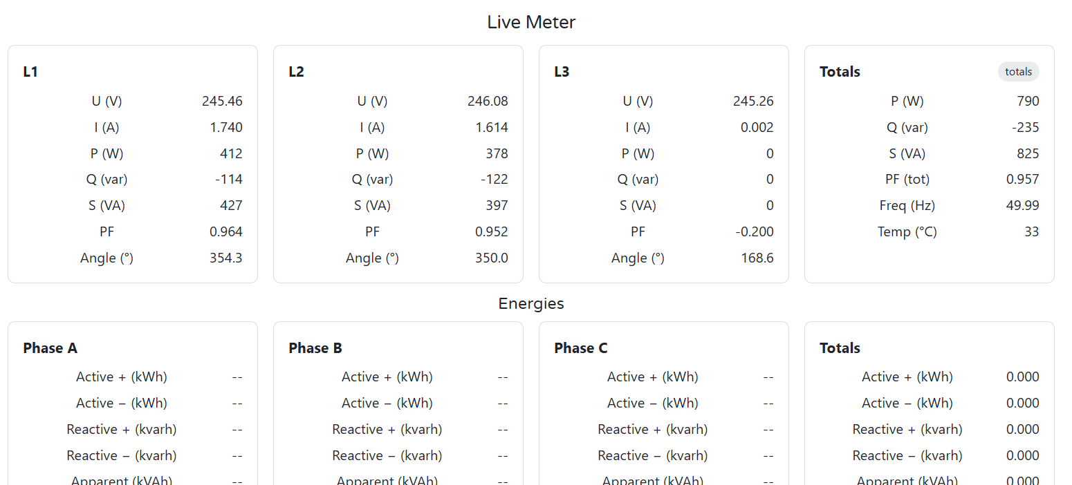
Live Meter View:
- U (V), I (A), P (W), Q (var), S (VA)
- PF, angle, frequency, temperature
- Totals and per-channel tiles
- Phase validation and wiring checks
Energies:
- Per phase + totals:
- Active (+ / –) in kWh
- Reactive (+ / –) in kvarh
- Apparent in kVAh
Use this screen to verify CT orientation, load phase mapping, and live alarm behavior during commissioning.
4.6 Getting Started (3 Phases)
Phase 1 — Wire
- 24 V DC to
V+ / GND(top left terminals) - Voltage inputs:
PE / N / L1 / L2 / L3- For single-phase: energize L1 only, tie L2/L3 → N
- CTs to
CT1/CT2/CT3with correct ± polarity (1 V or 333 mV RMS)- Arrow → load; shielded pairs preferred
- RS‑485 A/B/COM
- Use shielded twisted pair; terminate bus ends with 120 Ω
- (Optional) Relay outputs:
COM/NO/NC- Add snubber on inductive loads (RC/TVS)
- Ground panel PE and avoid bridging GND ↔ GND_ISO
👉 See: Installation & Quick Start
Phase 2 — Configure (WebConfig)
- Open
tools/ConfigToolPage.htmlin Chrome/Edge - Connect via USB‑C → Select port → Connect
- Set:
- Modbus Address / Baud
- Line Frequency, Sample Interval
- Alarm thresholds per L1/L2/L3/Totals
- Relay modes: Alarm or Modbus Controlled
- Map Buttons & LEDs (override, Ack, follow alarms)
- (Optional) Adjust U/I gains, save calibration
👉 See: WebConfig UI
Phase 3 — Integrate (Controller)
- Connect controller via RS‑485
- Match Modbus address / baud
- Poll:
- Input registers: meter values (U, I, P, Q, S, PF, angle, kWh, etc.)
- Coils: relays (600/601), Ack (610–613), button state
- Send:
- Coil writes: toggle relays, acknowledge alarms
- Use with:
- HomeMaster MicroPLC / MiniPLC
- SCADA / ESPHome
👉 See: Modbus RTU Communication & Integration Guide
✅ Verify
| Area | What to Check |
|---|---|
| LEDs | PWR = ON; TX/RX = blink during comms |
| Voltage | L1–L3 read ~230 V (or phase-neutral voltage) |
| Current |
5. ENM-223-R1 — Technical Specification
5.1 Diagrams & Pinouts
System Diagram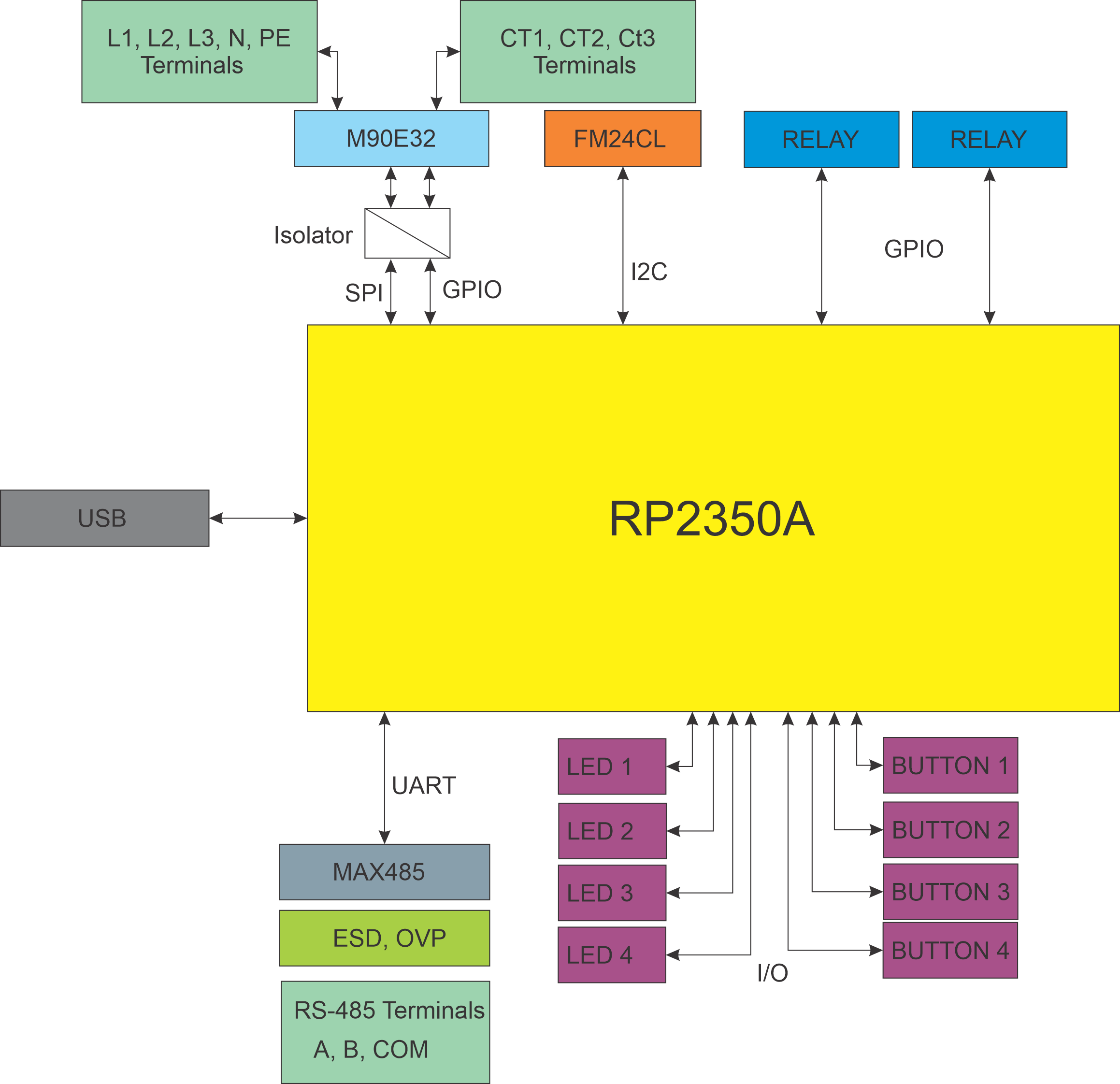
|
MCU Pinout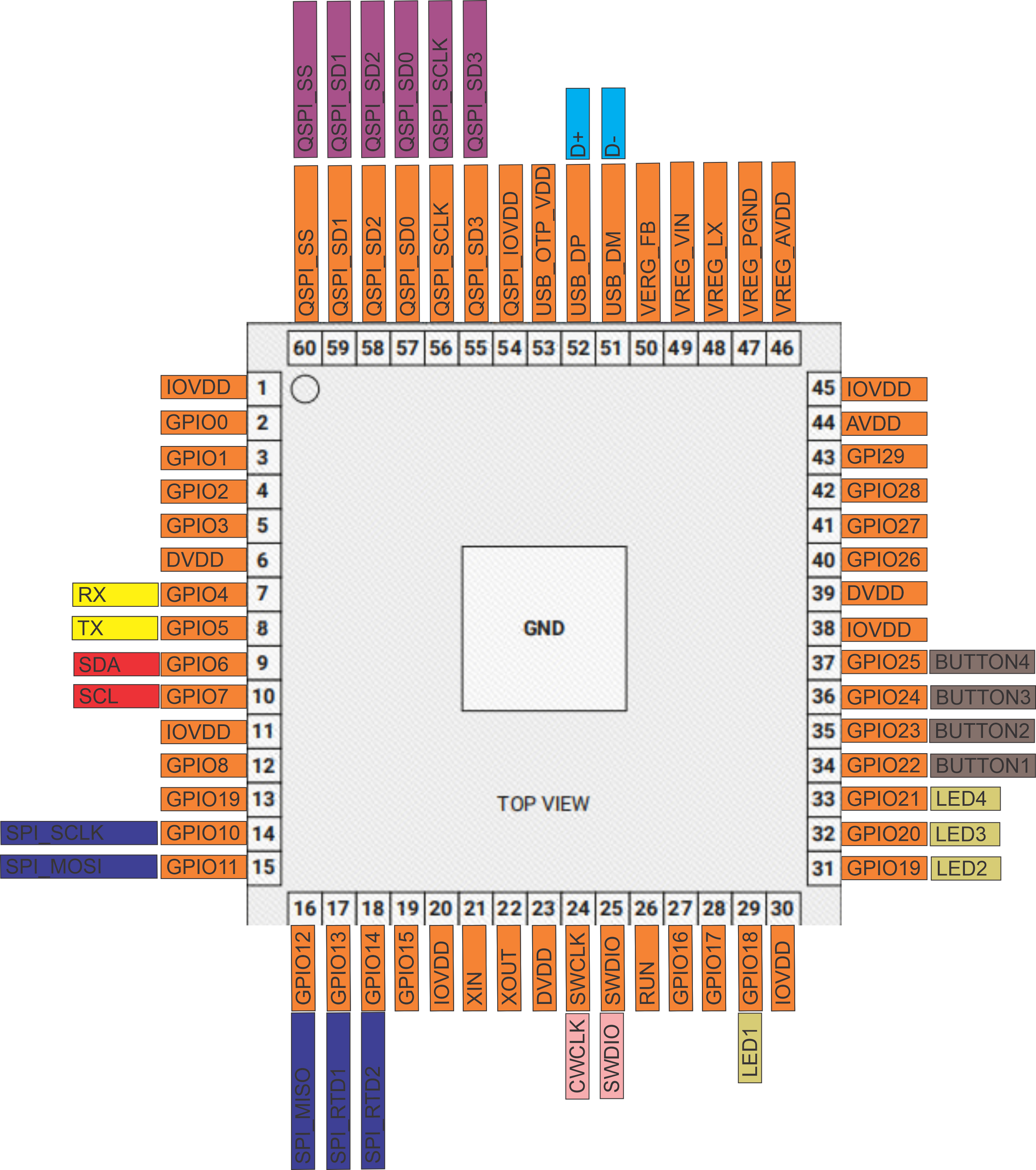
|
Field Board Terminal Map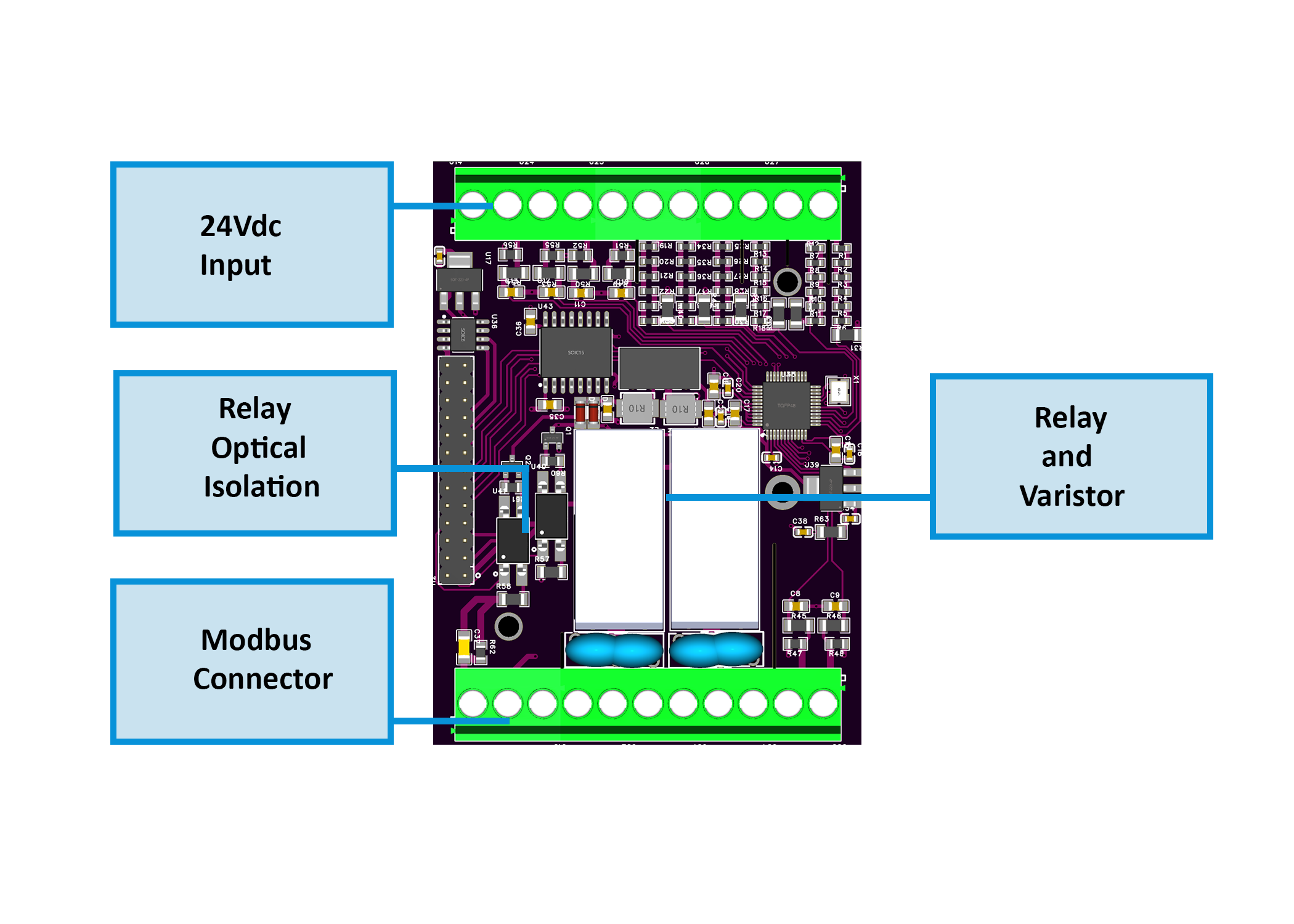
|
MCU Board Layout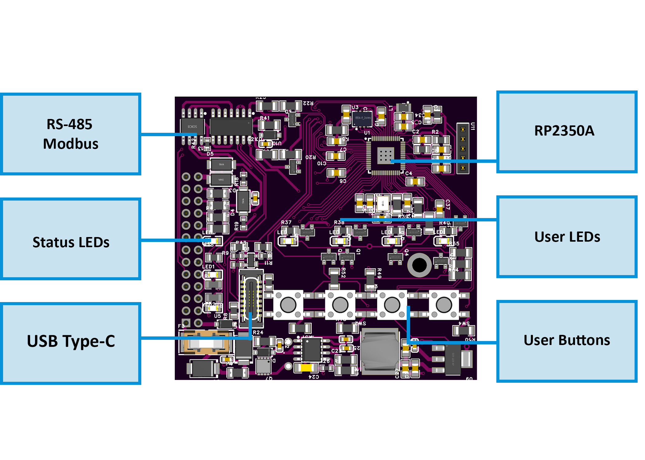
|
💡 Note: Pinouts correspond to hardware revision R1. Terminals are pluggable 5.08 mm pitch (26–12 AWG, torque 0.5–0.6 Nm).
5.2 I/O Summary
| Interface | Qty | Description |
|---|---|---|
| Voltage Inputs | 3 | L1 / L2 / L3–N, 85–265 V AC via precision divider to ATM90E32AS metering IC |
| Current Inputs | 3 | CT1–CT3, external 333 mV / 1 V RMS split-core CTs |
| Relay Outputs | 2 | SPDT dry contact, HF115F series, opto-driven; 5 A @ 250 VAC / 30 VDC (module limit) |
| User LEDs | 4 | Assignable status / override indicators (GPIO18–21) |
| Buttons | 4 | Momentary tactile switches (GPIO22–25) |
| RS-485 | 1 | A/B/COM, Modbus RTU, MAX485 transceiver |
| USB-C | 1 | Native USB 2.0 (Web Serial + firmware flashing), ESD-protected |
| Power Input | 1 | 24 V DC (22–28 V) logic supply, reverse & surge protected |
5.3 Absolute Electrical Specifications
| Parameter | Min | Typ | Max | Unit | Notes |
|---|---|---|---|---|---|
| Supply Voltage (V+) | 22 | 24 | 28 | V DC | SELV; reverse / surge protected input |
| Power Consumption | – | 1.85 | 3.0 | W | Module only, no external loads |
| Logic Rails | – | 3.3 / 5 | – | V | Buck (AP64501) + LDO (AMS1117-3.3) |
| Isolated Sensor Rails | – | +12 / +5 | – | V | From B0505S-1WR3 isolated DC-DC |
| Voltage Inputs | 85 | – | 265 | V AC | Divided to ATM90E32AS AFE |
| Current Inputs | – | 1 / 0.333 | – | V RMS | External CTs |
| Relay Outputs | – | – | 5 | A | SPDT; 250 VAC/30 VDC; varistor + snubber recommended |
| RS-485 Bus | – | 115.2 | – | kbps | MAX485; short-circuit limited; fail-safe bias |
| USB-C Port | – | 5 | 5.25 | V DC | Native USB; ESD protected |
| Operating Temp. | 0 | – | 40 | °C | ≤ 95 % RH non-condensing |
| Isolation (DC-DC) | – | 1.5 | 3.0 | kV DC | Metering domain via B0505S-1WR3 |
| Isolation (Digital) | – | 5.0 | – | kV RMS | ISO7761 6-ch isolator between MCU ↔ AFE |
🧩 Values validated from schematics and manufacturer datasheets for ATM90E32AS, ISO7761, B0505S-1WR3, HF115F, AP64501.
5.4 Connector / Terminal Map (Field Side)
| Block / Label | Pin(s) (left→right) | Function / Signal | Limits / Notes |
|---|---|---|---|
| POWER | V+, 0V | 24 V DC SELV input | Reverse / surge protected |
| VOLTAGE INPUT | PE, N, L1, L2, L3 | AC sensing (85–265 V AC) | Isolated domain |
| CT INPUT | CT1+, CT1–, CT2+, CT2–, CT3+, CT3– | External CT (333 mV / 1 V RMS) | Shielded pairs recommended |
| RS-485 | A, B, COM | Modbus RTU bus | Terminate 120 Ω at ends |
| RELAY 1 | NO, C, NC | SPDT dry contact | 5 A max @ 250 VAC/30 VDC |
| RELAY 2 | NO, C, NC | SPDT dry contact | 5 A max @ 250 VAC/30 VDC |
| USB-C | D+, D–, VBUS, GND | Web Serial / Setup | Not for field mount |
| LED / BTN Interface | – | Internal header MCU ↔ Field Board | Service only |
5.5 Reliability & Protection Specifics
- Primary Protection: Reverse-path diode + MOSFET high-side switch; distributed inline fuses
- Isolated rails: Independent +12 V / +5 V DC with LC filters; isolated returns (GND_ISO)
- Inputs: Per-channel TVS and RC filtering; debounced in firmware
- Relays: Coil driven via SFH6156 optocoupler → S8050 transistor → HF115F SPDT; RC/TVS suppression recommended for inductive loads
- RS-485: TVS (SMAJ6.8CA) + PTC; failsafe bias on idle; TX/RX LED feedback
- USB: PRTR5V0U2X ESD array on D+/D–; CC pull-downs per USB-C spec
- Memory Retention: FM24CL16B FRAM for energy counters (>10¹⁴ writes); W25Q32JV QSPI flash for firmware/config
5.6 Firmware / Functional Overview
- Alarm Engine: Four channels (L1–L3 + Totals); each has Alarm/Warning/Event rules
- Modes: Active-while / Latched-until-ack
- Metrics: Urms, Irms, P, Q, S, Frequency
- Relay Control: Per relay Enable / Invert / Group mode; Manual override (hold 3 s) via buttons
- LED Feedback: User-assignable LEDs for Alarms / Overrides / Events (Steady or Blink)
- Setup & Telemetry: WebConfig over USB-C; configure Modbus addr/baud, relay groups, thresholds, and live readings
- Data Retention: Energy and configuration stored in FRAM (non-volatile, instant writes)
5.7 Mechanical Details
| Property | Specification |
|---|---|
| Mounting | DIN rail EN 50022 (35 mm) |
| Material / Finish | PC / ABS V-0, matte light gray + smoke panel |
| Dimensions (L × W × H) | 70 × 90.6 × 67.3 mm (9 division units) |
| Weight | ~420 g |
| Terminals | 300 V / 20 A / 26–12 AWG (2.5 mm²) / torque 0.5–0.6 Nm / pitch 5.08 mm |
| Ingress Protection | IP20 (EN 60529) |
| Operating Temp. | 0–40 °C / ≤95 % RH (non-condensing) |
ENM-223-R1 Physical Dimensions (DIN-rail enclosure)
5.8 Standards & Compliance
| Standard / Directive | Description |
|---|---|
| Ingress Rating | IP20 (panel mount only) |
| Altitude Limit | ≤ 2000 m |
| Environment | RoHS / REACH compliant |
6. Modbus RTU Communication
The ENM‑223‑R1 communicates over RS‑485 (Modbus RTU) and supports:
- Real-time metering via Input Registers
- Configuration via Holding Registers
- Control and acknowledgment via Coils
- Status monitoring via Discrete Inputs
The device acts as a Modbus Slave and can be polled by a PLC, SCADA, ESPHome, or Home Assistant system.
6.1 Addressing & Protocol Settings
| Setting | Value |
|---|---|
| Default Address | 3 (configurable: 1–255) |
| Baud Rate | 19200 8N1 (configurable) |
| Physical Layer | RS‑485 (half-duplex, A/B/COM) |
| Function Codes | 0x01, 0x02, 0x03, 0x04, 0x05, 0x06, 0x10 |
| Termination | External 120 Ω at bus ends |
| Fail-safe Bias | Required on master side |
📌 Use the WebConfig tool over USB‑C to set Modbus address and baud rate.
6.2 Input Registers — Real-Time Telemetry (FC04)
| Address | Type | Metric | Unit | Scaling |
|---|---|---|---|---|
| 100–102 | U16 | Voltage L1/L2/L3 | V | ×0.01 |
| 110–112 | U16 | Current L1/L2/L3 | A | ×0.001 |
| 200–207 | S32 | Active Power (L1–3, Totals) | W | 1 |
| 210–217 | S32 | Reactive Power (L1–3, Totals) | var | 1 |
| 220–227 | S32 | Apparent Power (L1–3, Totals) | VA | 1 |
| 240–243 | S16 | Power Factor L1–3, Total | – | ×0.001 |
| 244–246 | S16 | Phase Angle L1–3 | ° | ×0.1 |
| 250 | U16 | Frequency | Hz | ×0.01 |
| 251 | S16 | Temperature (internal) | °C | 1 |
6.3 Energy Registers (Wh/varh/VAh, FC04)
| Address | Type | Energy Type | Phase / Total | Unit |
|---|---|---|---|---|
| 300–307 | U32 | Active Energy (+ import) | A/B/C/Totals | Wh |
| 308–315 | U32 | Active Energy (− export) | A/B/C/Totals | Wh |
| 316–323 | U32 | Reactive Energy (+ inductive) | A/B/C/Totals | varh |
| 324–331 | U32 | Reactive Energy (− capacitive) | A/B/C/Totals | varh |
| 332–339 | U32 | Apparent Energy | A/B/C/Totals | VAh |
Energy values are 32-bit unsigned integers (Hi/Lo word pairs).
6.4 Holding Registers — Configuration (FC03/06/16)
| Address | Type | Description | Range / Units |
|---|---|---|---|
| 400 | U16 | Sample Interval | 10–5000 ms |
| 401 | U16 | Line Frequency | 50 or 60 Hz |
| 402 | U16 | Sum Mode | 0 = algorithmic 1 = absolute |
| 403 | U16 | Ucal Gain | 1–65535 |
| 410–420 | U16 | Ugain A/B/C | 16-bit |
| 421–431 | S16 | Uoffset A/B/C | 16-bit |
| 440–450 | U16 | Igain A/B/C | 16-bit |
| 451–461 | S16 | Ioffset A/B/C | 16-bit |
| 499 | U16 | Factory Reset Trigger | Write 1 to reset |
6.5 Coils — Output Control (FC01/05/15)
| Address | Description |
|---|---|
| 600 | Relay 1 Control (ON/OFF) |
| 601 | Relay 2 Control (ON/OFF) |
| 610–613 | Alarm Acknowledgment (L1–L3, Totals) |
6.6 Discrete Inputs — Read-only Status (FC02)
| Address | Description |
|---|---|
| 500–503 | LED Status (U.1–U.4) |
| 520–523 | Button Press (1–4) |
| 540–541 | Relay State (1–2) |
| 560–571 | Alarm/Warning/Event flags |
6.7 Scaling Summary
| Metric | Register Type | Scale Factor |
|---|---|---|
| Voltage (V) | Input Register | ÷100 |
| Current (A) | Input Register | ÷1000 |
| Power Factor | Input Register | ÷1000 |
| Frequency (Hz) | Input Register | ÷100 |
| Angle (°) | Input Register | ÷10 |
| Energy (Wh) | 32-bit Input | 1 |
6.8 Polling Best Practices
- Typical polling rate: 1 s for live data (powers, voltages, current)
- Energy: poll less often (e.g. every 5–10 s)
- Batch reads: Use FC04 and FC03 with multi-register reads for speed
- Avoid writing frequently to EEPROM-backed registers (e.g., Ucal or gains)
- Coils: Fast updates (e.g. overrides) okay; no debounce needed
🛠 To reduce bus collisions, stagger multiple ENMs on a shared RS‑485 bus using different poll intervals and address spacing.
6.9 Modbus Integration Example (MiniPLC)
modbus_controller:
  - id: enm223
    address: 3
    modbus_id: rtu_bus
    update_interval: 1s

sensor:
  - platform: modbus_controller
    modbus_controller_id: enm223
    name: "Urms L1"
    register_type: read
    address: 100
    value_type: U_WORD
    unit_of_measurement: "V"
    accuracy_decimals: 2
    filters:
      - multiply: 0.01

switch:
  - platform: modbus_controller
    modbus_controller_id: enm223
    name: "Relay 1"
    register_type: coil
    address: 600
7. ESPHome Integration Guide (MicroPLC/MiniPLC + ENM‑223‑R1)
The HomeMaster controller (MiniPLC or MicroPLC) running ESPHome acts as the Modbus RTU master over RS‑485. It polls one or more ENM‑223‑R1 modules and publishes all sensors, relays, LEDs, and alarms into Home Assistant.
No Home Assistant add-ons are required — all logic runs on the ESPHome controller.
7.1 Architecture & Data Flow
- Topology: Home Assistant → ESPHome (MicroPLC) → RS‑485 → ENM‑223‑R1
- Roles:
- ENM: metering, alarm rules, relays, LEDs, buttons
- ESPHome: Modbus polling, sensor/relay control, entity publishing
- HA: dashboards, energy view, automations
LED mappings, alarm logic, and override behavior are configured on the ENM module (via WebConfig). Home Assistant only reacts to exposed states.
7.2 Prerequisites (Power, Bus, I/O)
1. Power
- ENM: 24 V DC → V+ / 0V
- Controller: per spec
- If separate PSUs: share COM/GND between controller and ENM
2. RS‑485 Bus
- A—A, B—B (twisted pair), COM shared
- Terminate with 120 Ω resistors at both ends
- Default speed: 19200 baud, set in WebConfig
3. Field I/O
- Voltage inputs: L1, L2, L3, N, PE
- CTs: CT1–CT3 (1 V or 333 mV)
- Relays: dry contact, driven by internal logic or Modbus
- Buttons / LEDs: wired to MCU, mapped in firmware/UI
7.3 ESPHome Minimal Config (Enable Modbus + Import ENM Package)
uart:
  id: uart1
  tx_pin: 17
  rx_pin: 16
  baud_rate: 19200
  stop_bits: 1

modbus:
  id: rtu_bus
  uart_id: uart1

modbus_controller:
  - id: enm223_1
    address: 4
    modbus_id: rtu_bus
    update_interval: 1s

packages:
  enm223_1:
    url: https://github.com/isystemsautomation/HOMEMASTER
    ref: main
    files:
      - path: ENM-223-R1/Firmware/default_enm_223_r1_plc.yaml
        vars:
          enm_id: enm223_1
          enm_address: 4
          enm_prefix: "ENM #1"
7.4 Entities Exposed by the Package
Binary Sensors
- Relay states
- Button presses
- LED status
- Alarm conditions (Alarm / Warning / Event)
Sensors
- Urms, Irms L1/L2/L3
- Power (P, Q, S) totals
- Frequency, PF, Angle
- Energies: kWh, kvarh, kVAh (active/reactive/apparent)
Switches
- Relay 1/2 (Modbus coil 600/601)
- Acknowledge coils 610–613
- Override controls (force override toggle, hold-style)
Numbers (Optional)
- Sample interval
- Calibration gains (Ugain / Igain)
7.6 Using Your MiniPLC YAML with ENM
- Keep existing
uart:andmodbus:blocks - Add the
packages:block (as shown) and setenm_addressfrom WebConfig - Flash the controller — ESPHome discovers all sensors/entities automatically
- Add HA dashboard cards and
switchesfor relay, override, and ack actions
7.7 Home Assistant Setup & Automations
- Go to: Settings → Devices & Services → ESPHome → Add by hostname or IP
- Dashboard auto-discovers:
- Energies (for HA Energy view)
- Relays, buttons, LEDs
- Alarm states
- You can create:
- Energy Dashboard source:
VAh TotalorAP Total - Automation:
- Energy Dashboard source:
8. Programming & Customization
8.1 Supported Languages
- MicroPython
- C/C++
- Arduino IDE
8.2 Flashing via USB-C
- Connect USB-C to your PC.
- Enter boot/flash mode if required.
- Upload the provided firmware/source.
Boot/Reset combinations:
- Buttons 1 + 2 → forces the module into BOOT mode
- Buttons 3 + 4 → triggers a hardware RESET
These combinations are handled in hardware. Use them when flashing or manually rebooting the module.
🧭 Button layout reference:
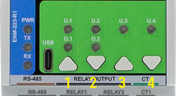
8.3 Arduino IDE Setup
- Board Profile: Generic RP2350
- Flash Size: 2MB (Sketch: 1MB, FS: 1MB)
- Recommended Libraries:
#include <Arduino.h>
#include <SPI.h>
#include <SimpleWebSerial.h>
#include <Arduino_JSON.h>
#include <LittleFS.h>
#include <math.h>
#include <limits>
- Pin Notes:
- Buttons: GPIO22–25
- LEDs: GPIO18–21
- RS-485: MAX485, DE/RE control over TX
- USB: native, no UART bridge
8.4 Firmware Updates
- Upload via USB-C using Arduino IDE or PlatformIO
- Enter boot mode (Buttons 1 + 2)
- Upload
default_enm_223_r1.inofrom/firmware/ - Configuration is preserved (stored in LittleFS)
- Energy counters are safe (stored in FRAM)
9. Maintenance & Troubleshooting
| Symptom | Fix or Explanation |
|---|---|
| Relay won’t activate | May be in override; check relay logic mode |
| RS-485 not working | A/B reversed or un-terminated bus |
| LED doesn’t light up | Reassign in WebConfig or check GPIO18–21 |
| Button unresponsive | Test using WebConfig > Button state live |
| CRC Errors | Confirm baud, address, and wiring (A/B swap) |
| Negative Power Reading | Flip CT or check phase/CT alignment |
10. Open Source & Licensing
| Component | License |
|---|---|
| Hardware | CERN-OHL-W v2.0 |
| Firmware | GPLv3 |
| Config Tool | MIT |
11. Downloads
The following key project resources are included in this repository:
🧠 Firmware (Arduino/PlatformIO)
firmware/default_enm_223_r1.ino
Core firmware implementing Modbus RTU, alarm logic, relays, LED control, overrides, and WebConfig support.🧰 WebConfig Tool
tools/ConfigToolPage.html
HTML-based USB Web Serial interface for live configuration, calibration, alarm setup, and logic assignment.🖼 Images & UI Diagrams
Images/
Contains front-panel photos, system diagrams, wiring illustrations, and screenshots from WebConfig UI.📐 Hardware Schematics
Schematics/
Includes PDF schematics for Field Board and MCU Board — ideal for developers, reviewers, or third-party modders.📄 Datasheets & Manuals
ENM-223-R1 Datasheet.pdf
Covers full electrical and mechanical specs, terminal layout, block diagram, and pinout.📦 ESPHome YAML Templates
ENM223R1_ESPHome_Integration_Guide.md
Ready-to-usepackages:block for ESPHome controllers, with sensors, relays, alarms, override logic, and Home Assistant tips.
🔁 Latest releases can also be found in the Releases tab or in the
Firmware/directory.
12. Support
If you need help using or configuring the ENM‑223‑R1 module, the following support options are available:
🛠 Official Resources
🧰 WebConfig Tool (USB-C)
Configure the module directly from your browser — no drivers or software required.📘 Official Support Portal
Includes setup guides, firmware help, diagnostics, and contact form.
📡 Community & Updates
- 🔧 Hackster Projects — System integration, code samples, wiring
- 📺 YouTube Channel — Module demos, walkthroughs, and tutorials
- 💬 Reddit Community — Questions, answers, contributions
- 📸 Instagram — Visual updates and field applications
ENM-223-R1 — 3‑Phase Power Metering & I/O Module
Firmware Version: 2025-09 snapshot
ENM-223-R1 — 3-Phase Power Metering & I/O Module
HOMEMASTER – Modular control. Custom logic.
Module Description
The ENM-223-R1 is a configurable smart I/O module designed for 3-phase power quality and energy metering.
It includes 3 voltage inputs, 3 current channels, 2 relays, and optional 4 buttons / 4 LEDs, with configuration via WebConfig using USB-C (Web Serial).
It connects over RS-485 (Modbus RTU) to a MicroPLC/MiniPLC, enabling use in energy monitoring, automation, and smart building applications.
Table of Contents
- 1. Introduction
- 2. Use Cases
- 3. Safety Information
- 4. Installation & Quick Start
- 5. MODULE-CODE — Technical Specification
- 6. Modbus RTU Communication
- 7. ESPHome Integration Guide (if applicable)
- 8. Programming & Customization
- 9. Maintenance & Troubleshooting
- 10. Open Source & Licensing
- 11. Downloads
- 12. Support
1. Introduction
1.1 Overview of the ENM‑223‑R1 Module ⚡
The ENM‑223‑R1 is a modular 3‑phase energy metering + I/O device for power monitoring, automation, and local control. It features 3 voltage channels (L1/L2/L3‑N), 3 current channels (external CTs), 2 SPDT relays, 4 user LEDs, and 4 buttons—all driven by an RP2350 MCU with QSPI flash and a dedicated ATM90E32AS metering IC.
It integrates with MiniPLC/MicroPLC controllers or any Modbus RTU master over RS‑485, and it’s configured in‑browser via USB‑C Web Serial (no drivers). Typical uses include energy dashboards, demand response, alarm‑driven relay control, and building automation. Defaults ship as Modbus address 3 @ 19200 8N1 (changeable in WebConfig).
Quick device flow:
Wire Lx/N/PE + CTs → set address/baud in WebConfig → calibrate gains/offsets → define alarms per L1/L2/L3/Totals → map relays/LEDs/buttons → connect RS‑485 A/B (and GND if separate PSUs) → poll via Modbus.
1.2 Features & Architecture
Core Capabilities
| Subsystem | Qty | Description |
|---|---|---|
| Voltage Inputs | 3 | L1/L2/L3‑N measurement (divider network on FieldBoard) feeding ATM90E32AS |
| Current Inputs | 3 | Differential CT inputs (IAP/IAN, IBP/IBN, ICP/ICN) with filtering/burdens |
| Relays | 2 | SPDT dry contacts (NO/NC); opto‑driven; alarm‑ or Modbus‑controlled |
| LEDs | 4 | User LEDs; sources: overrides/alarms/warnings/events; steady or blink |
| Buttons | 4 | User actions (toggle relays/LEDs, overrides, acks) with live state feedback |
| Metering & Energy | — | ATM90E32AS: Urms/Irms, P/Q/S, PF, angle, freq; energy kWh/kvarh/kVAh (phase & totals) |
| Config UI | Web Serial | In‑browser WebConfig over USB‑C (Chrome/Edge); live meter, calibration, alarms, relays, LEDs, buttons |
| Modbus RTU | RS‑485 | Multi‑drop slave; address 1…255; baud 9600–115200 (default 19200 8N1) |
| MCU | RP2350 + QSPI | Dual‑core MCU, native USB, external W25Q32 flash; RS‑485 via MAX485 transceiver |
| Power | 24 VDC | Buck to 5 V → 3.3 V LDO; isolated analog domain via B0505S DC‑DC + ISO7761 |
| Protection | TVS, PTC, fuses | Surge/ESD on USB & RS‑485; resettable fuses on field I/O; reverse‑polarity protection |
1.3 System Role & Communication 🍰
The ENM‑223‑R1 is a smart Modbus RTU slave. It executes local alarm logic (thresholds & acks) and mirrors states/values to a PLC or SCADA via registers/coils. Configuration (meter options, calibration, relay/LED logic, button actions, Modbus address/baud) is done via USB‑C WebConfig, stored to non‑volatile memory.
| Role | Description |
|---|---|
| System Position | Expansion meter+I/O on the RS‑485 trunk (A/B/GND) |
| Master Controller | MiniPLC / MicroPLC or any third‑party Modbus RTU master (polling) |
| Address / Baud | Configurable 1…255 / 9600–115200; factory default: ID 3 @ 19200 8N1 |
| Bus Type | RS‑485 half‑duplex; termination/bias per bus rules; share GND if separate PSUs |
| USB‑C Port | Setup/diagnostics via Chromium browser (Web Serial); native USB D+/D− to MCU |
| Default Modbus ID | 3 (change in WebConfig) |
| Daisy‑Chaining | Multi‑drop on shared A/B; ensure unique IDs and end‑of‑line termination |
Note: The UI exposes per‑channel Alarm / Warning / Event with min/max thresholds and Ack required option; relays can follow selected alarm kinds or be Modbus‑controlled. Buttons can toggle/override relays; LEDs reflect overrides or alarm states.
2. Use Cases
This section outlines practical application examples for the ENM‑223‑R1 module. Each use case includes a functional goal and a clear configuration procedure using the WebConfig tool and/or Modbus RTU integration.
These templates are applicable in energy management, automation, industrial control, and building infrastructure deployments.
2.1 Overcurrent Alarm with Manual Reset
Purpose: Activate Relay 1 when current exceeds a configured threshold and hold it until manually acknowledged.
Configuration:
- Alarms → Channel:
Totals- Enable Alarm
- Metric:
Current (Irms) - Max threshold: e.g.
> 5000(for 5 A) - Enable Ack required
- Relays → Relay 1
- Mode:
Alarm Controlled - Channel:
Totals, Kinds:Alarm
- Mode:
- LEDs → LED 1
- Source:
Alarm Totals, Mode:Steady
- Source:
- Acknowledge: via Web UI, Modbus coils
610–613, or front panel button (if assigned)
2.2 Manual Override for Load Control
Purpose: Allow field operators to override Relay 2 using a button, regardless of Modbus or automation control.
Configuration:
- Relays → Relay 2
- Mode:
Modbus Controlled - Enabled at power-on
- Mode:
- Buttons → Button 2
- Action:
Override Relay 2 (hold 3s)
- Action:
- LEDs → LED 2
- Source:
Override R2, Mode:BlinkorSteady
- Source:
Holding the button for 3 seconds enters override mode. A short press toggles the relay. Holding again exits override mode.
2.3 Environmental Voltage/Frequency Alarm with Auto-Clear
Purpose: Detect power quality faults (sag/swell or freq drift), activate Relay 1 as an output, and auto-reset when back in range.
Configuration:
- Alarms → Channel:
L1- Enable Alarm
- Metric:
Voltage (Urms) - Min:
21000(210 V), Max:25000(250 V) - Leave Ack required unchecked
- Relays → Relay 1
- Mode:
Alarm Controlled, Channel:L1, Kinds:Alarm
- Mode:
- LEDs → LED 1
- Source:
Alarm L1
- Source:
2.4 Staged Load Shedding via Modbus Scenes
Purpose: Use a controller to shed non-critical loads as power consumption increases.
Configuration:
- Relays → Relay 1 and Relay 2
- Mode:
Modbus Controlled
- Mode:
- In PLC logic:
- Monitor
Totals S (VA)via Input Register - If
S > 8000, write coil600 = OFF(Relay 1) - If
S > 10000, write coil601 = OFF(Relay 2) - Restore relays when values drop below defined hysteresis limits
- Monitor
Ideal for HVAC or lighting where priority-based power shedding is needed.
Summary Table
| Use Case | Feature Used | Reset Method | Relay Mode |
|---|---|---|---|
| Overcurrent Alarm + Ack | Alarms, Ack, Relay 1 | Manual (Ack) | Alarm Controlled |
| Manual Override via Button | Button override, LED | Button toggle | Modbus Controlled |
| Voltage/Frequency Fault Auto-Reset | Alarm (no ack), Relay | Auto (value returns) | Alarm Controlled |
| Load Shedding (Staged Scenes) | PLC Modbus, Relay 1 & 2 | PLC-controlled | Modbus Controlled |
🛠 All parameters are configurable via USB‑C WebConfig. Modbus control assumes master-side logic (PLC, SCADA, or MicroPLC/MiniPLC).
3. Safety Information
These safety guidelines apply to the ENM‑223‑R1 3‑phase metering and I/O module. Ignoring them may result in equipment damage, system failure, or personal injury.
⚠️ Mixed Voltage Domains — This device contains both SELV (e.g., 24 V DC, RS‑485, USB) and non-SELV mains inputs (85–265 V AC). Proper isolation, wiring, and grounding are required. Never connect SELV and mains GND together.
3.1 General Requirements
| Requirement | Detail |
|---|---|
| Qualified Personnel | Installation and servicing must be done by qualified personnel familiar with high-voltage and SELV control systems. |
| Power Isolation | Disconnect both 24 V DC and voltage inputs (Lx/N) before servicing. Use lockout/tagout where applicable. |
| Environmental Limits | Mount in a clean, sealed enclosure. Avoid condensation, conductive dust, or vibration. |
| Grounding | Bond the panel to PE. Wire PE and N to the module. Never bridge GND_ISO to logic GND. |
| Voltage Compliance | CT inputs: 1 V or 333 mV RMS only. Voltage inputs: 85–265 V AC. Use upstream fusing and surge protection. |
3.2 Installation Practices
| Task | Guidance |
|---|---|
| ESD Protection | Handle only by the case. Use antistatic wrist strap and surface when the board is exposed. |
| DIN Rail Mounting | Mount securely on 35 mm DIN rail inside an IP-rated cabinet. Allow cable slack for strain relief. |
| Wiring | Use correct gauge wire and torque terminal screws. Separate relay, CT, and RS‑485 wiring. |
| Isolation Domains | Respect isolation: Do not bridge GND_ISO to GND. Keep analog and logic grounds isolated. |
| Commissioning | Before power-up, verify voltage wiring, CT polarity, RS‑485 A/B orientation, and relay COM/NO/NC routing. |
3.3 I/O & Interface Warnings
⚡ Power
| Area | Warning |
|---|---|
| 24 V DC Input | Use a clean, fused SELV power source. Reverse polarity is protected but may disable the module. |
| Voltage Input | Connect L1/L2/L3/N/PE only within rated range (85–265 V AC). Use circuit protection upstream. |
| Sensor Domain | Use CTs with 1 V or 333 mV RMS output. Never apply 5 A directly. Observe polarity and shielding. |
🧲 Inputs & Relays
| Area | Warning |
|---|---|
| CT Inputs | Accept only voltage-output CTs. Reversing polarity may affect power sign. Use GND_ISO reference. |
| Relay Outputs | Dry contacts only. Rated: 5 A @ 250 VAC or 30 VDC. Use snubber (RC/TVS) for inductive loads. |
🖧 Communication & USB
| Area | Warning |
|---|---|
| RS‑485 Bus | Use twisted pair. Terminate at both ends. Match A/B polarity. Share GND if powered from different PSUs. |
| USB-C (Front) | For setup only. Not for permanent field connection. Disconnect during storms or long idle periods. |
🎛 Front Panel
| Area | Warning |
|---|---|
| Buttons & LEDs | Can override relays or trigger alarms. Use firmware settings or lockout for safety-critical installs. |
🛡 Shielding & EMC
| Area | Recommendation |
|---|---|
| Cable Shields | Terminate at one side only (preferably PLC/controller). Route away from VFDs and high-voltage cabling. |
✅ Pre‑Power Checklist
- All wiring is torqued, labeled, and strain-relieved
- No bridge between logic GND and GND_ISO
- PE and N are wired to terminals
- RS‑485 A/B polarity and 120 Ω termination confirmed
- Relay loads do not exceed 5 A or contact voltage rating
- CTs installed with correct polarity and securely landed
- Voltage inputs fused, protected, and within spec (85–265 V AC)
🧷 Tip: In single-phase installations, energize L1 and tie L2/L3 → N to prevent phantom voltages.
4. Installation & Quick Start
The ENM‑223‑R1 connects to your system over RS‑485 (Modbus RTU) and supports configuration via USB‑C WebConfig. Setup involves:
1) Physical wiring, 2) Digital setup (WebConfig → Modbus or PLC/ESPHome control).
4.1 What You Need
| Category | Item / Notes |
|---|---|
| Hardware | ENM‑223‑R1 module: DIN-rail, 3 voltage channels, 3 CTs, 2 relays, 4 buttons, 4 LEDs, RS‑485, USB‑C |
| Controller | MicroPLC, MiniPLC, or any Modbus RTU master |
| 24 VDC Power (SELV) | Regulated 24 V DC @ ~100–200 mA |
| RS‑485 Cable | Twisted pair for A/B + COM/GND; external 120 Ω end-termination |
| USB‑C Cable | For WebConfig setup via Chromium browser (Chrome/Edge) |
| Software | Web browser (Web Serial enabled), ConfigToolPage.html |
| Field Wiring | L1/L2/L3/N/PE → voltage inputs, CT1/2/3 → external CTs |
| Load Wiring | Relay outputs (NO/COM/NC); observe relay max rating and use snubbers on inductive loads |
| Isolation Domains | GND (logic) ≠ GND_ISO (metering); never bond these directly |
| Tools | Torque screwdriver, ferrules, USB-capable PC, 120 Ω terminators if needed |
Quick Path
① Mount → ② wire 24 VDC + RS‑485 (A/B/COM) → ③ connect USB‑C → ④ launch WebConfig →
Set Address/Baud → assign Inputs/Relays/LEDs → confirm data → ⑤ disconnect USB → hand control to Modbus master.
4.2 Power
The ENM‑223‑R1 uses 24 V DC input for its interface domain and internally isolates metering circuits.
- Power Terminals: Top left:
V+and0V - Voltage Range: 22–28 V DC (nominal 24 V)
- Typical Current: 50–150 mA (relays off/on)
- Protection: Internally fused, reverse-polarity protected
- Logic domain: Powers MCU, RS‑485, LEDs, buttons, relays
4.2.1 Sensor Isolation
- Metering IC (ATM90E32AS) is powered from an isolated 5 V rail
- Analog domain uses GND_ISO, fully isolated from GND
- Do not connect GND_ISO ↔ GND; isolation via B0505S + ISO7761
Only voltage inputs (Lx-N) and CTs connect to the isolated domain.
4.2.2 Power Tips
- Do not power relays or outputs from metering-side inputs
- Use separate fusing on L1–L3
- Tie L2, L3 → N if using single-phase only (prevents phantom voltage)
- Confirm PE is wired — improves stability & safety
4.3 Networking & Communication
4.3.1 RS‑485 (Modbus RTU)
Physical
| Terminals | Description |
|---|---|
A, B |
Differential signal pair (twisted/shielded) |
COM/GND |
Logic reference (tie GNDs if on separate supplies) |
Cable & Topology
- Twisted pair (with or without shield)
- Terminate with 120 Ω at each bus end (not inside module)
- Biasing resistors (pull-up/down) should be on the master
Defaults
| Setting | Value |
|---|---|
| Modbus Address | 3 |
| Baud Rate | 19200 |
| Format | 8N1 |
| Address Range | 1–247 |
🧷 Reversed A/B will cause CRC errors — check if no response.
4.3.2 USB‑C (WebConfig)
Purpose: Web-based configuration tool over native USB Serial. Supports:
- Live readings
- Address/baudrate config
- Phase mapping
- Relay/button/LED logic
- Alarm setup
- Calibration (gains/offsets)
Steps
- Connect USB‑C to PC (Chrome/Edge)
- Open
tools/ConfigToolPage.html - Click Connect, select ENM serial port
- Configure settings: address, relays, LEDs, alarms, calibration
- Click Save & Disconnect when finished
⚠️ If Connect is greyed out: check browser support, OS permissions, and close any other apps using the port.
4.4 Installation & Wiring
Use diagrams and explain:
- Inputs
- Relays
- Sensor rails (12/5V)
- RS-485 terminals
- USB port
4.5 Software & UI Configuration
The ENM‑223‑R1 is configured using the browser‑based WebConfig Tool
(tools/ConfigToolPage.html) over USB‑C.
No drivers or software installation is required — configuration happens directly via Web Serial API (Chrome/Edge).
- WebConfig refreshes live data every 1 s.
- Click into a field to pause refresh for that field.
- Press Enter to apply a change.
- All settings are stored in non‑volatile flash.
1) Modbus Setup (Address & Baud)
- Click Connect and select the USB serial port.
- The Active Modbus Configuration bar shows the current Address and Baud Rate.
- You can configure:
- Modbus Address:
1–255(default =3) - Baud Rate:
9600 / 19200 / 38400 / 57600 / 115200(default =19200)
- Modbus Address:
- Changes are live and applied on selection.
- If you change baud or address, remember to reconnect the controller with updated settings.
2) Meter Options & Calibration
Meter Options
- Line Frequency: 50 / 60 Hz (affects metering IC behavior)
- Sum Mode:
0 = algorithmic(P = P1 + P2 + P3)1 = absolute(P = |P1| + |P2| + |P3|)
- Ucal (gain): global voltage scaling multiplier
- Sample Interval (ms): rate at which readings update (10–5000 ms)
Calibration (per phase A/B/C)
- Ugain / Igain: scaling gains (16-bit, 0–65535)
- Uoffset / Ioffset: calibration offsets (signed)
- Press Enter after editing to write the value to the module.
3) Alarms / Inputs (Per‑Channel Rules)
The ENM has 4 measurement channels: L1, L2, L3, and Totals.
Each channel supports:
- 3 rule slots: Alarm, Warning, Event
- Metric types:
- Voltage (Urms)
- Current (Irms)
- Active Power P
- Reactive Power Q
- Apparent Power S
- Frequency
You can configure:
- Enable toggle
- Metric, Min, and Max thresholds
- Ack required — latches the Alarm state until acknowledged
Acknowledgment:
- Press Ack L1–L3 / Totals in UI
- Or write to Modbus coil (
610–613)
💡 ENM has no digital inputs (DIs). These rules are “virtual inputs” based on real-time metering data.
4) Relay Logic Modes
Each of the two onboard SPDT relays can be configured independently.
Options:
| Setting | Description |
|---|---|
| Enabled at Power-On | Relay state after boot (on/off) |
| Inverted (active-low) | Affects both relays; sets low = ON |
| Mode | None, Modbus Controlled, or Alarm Controlled |
| Toggle | Manually toggle the relay from the UI |
| Alarm Control Options | Select Channel: L1–L3 or Totals and which kinds to follow: Alarm / Warning / Event |
In Alarm Controlled mode, direct Modbus writes may be blocked when an alarm is active.
5) Button & LED Mapping
Buttons (1–4)
Each button can be mapped to:
NoneToggle Relay 1/2Toggle LED 1–4Override Relay 1/2 (hold 3s)- Hold 3 s to enter override
- Short press toggles the relay
- Hold again to exit override
User LEDs (1–4)
Each LED has:
- Mode:
Steady (when active)orBlink (when active) - Source:
Override R1/R2- Alarm, Warning, Event — for any channel
Any (A|W|E)— a combined indicator per channel
💡 Use
Override R1as LED 1 source to give a clear local override status.
6) Live Meter & Energies
Live Meter View:
- U (V), I (A), P (W), Q (var), S (VA)
- PF, angle, frequency, temperature
- Totals and per-channel tiles
- Phase validation and wiring checks
Energies:
- Per phase + totals:
- Active (+ / –) in kWh
- Reactive (+ / –) in kvarh
- Apparent in kVAh
Use this screen to verify CT orientation, load phase mapping, and live alarm behavior during commissioning.
4.6 Getting Started (3 Phases)
Phase 1 — Wire
- 24 V DC to
V+ / GND(top left terminals) - Voltage inputs:
PE / N / L1 / L2 / L3- For single-phase: energize L1 only, tie L2/L3 → N
- CTs to
CT1/CT2/CT3with correct ± polarity (1 V or 333 mV RMS)- Arrow → load; shielded pairs preferred
- RS‑485 A/B/COM
- Use shielded twisted pair; terminate bus ends with 120 Ω
- (Optional) Relay outputs:
COM/NO/NC- Add snubber on inductive loads (RC/TVS)
- Ground panel PE and avoid bridging GND ↔ GND_ISO
👉 See: Installation & Quick Start
Phase 2 — Configure (WebConfig)
- Open
tools/ConfigToolPage.htmlin Chrome/Edge - Connect via USB‑C → Select port → Connect
- Set:
- Modbus Address / Baud
- Line Frequency, Sample Interval
- Alarm thresholds per L1/L2/L3/Totals
- Relay modes: Alarm or Modbus Controlled
- Map Buttons & LEDs (override, Ack, follow alarms)
- (Optional) Adjust U/I gains, save calibration
👉 See: WebConfig UI
Phase 3 — Integrate (Controller)
- Connect controller via RS‑485
- Match Modbus address / baud
- Poll:
- Input registers: meter values (U, I, P, Q, S, PF, angle, kWh, etc.)
- Coils: relays (600/601), Ack (610–613), button state
- Send:
- Coil writes: toggle relays, acknowledge alarms
- Use with:
- HomeMaster MicroPLC / MiniPLC
- SCADA / ESPHome
👉 See: Modbus RTU Communication & Integration Guide
✅ Verify
| Area | What to Check |
|---|---|
| LEDs | PWR = ON; TX/RX = blink during comms |
| Voltage | L1–L3 read ~230 V (or phase-neutral voltage) |
| Current |
5. ENM-223-R1 — Technical Specification
5.1 Diagrams & Pinouts
|
System Diagram
|
MCU Pinout
|
|
Field Board Terminal Map
|
MCU Board Layout
|
💡 Note: Pinouts correspond to hardware revision R1. Terminals are pluggable 5.08 mm pitch (26–12 AWG, torque 0.5–0.6 Nm).
5.2 I/O Summary
| Interface | Qty | Description |
|---|---|---|
| Voltage Inputs | 3 | L1 / L2 / L3–N, 85–265 V AC via precision divider to ATM90E32AS metering IC |
| Current Inputs | 3 | CT1–CT3, external 333 mV / 1 V RMS split-core CTs |
| Relay Outputs | 2 | SPDT dry contact, HF115F series, opto-driven; 5 A @ 250 VAC / 30 VDC (module limit) |
| User LEDs | 4 | Assignable status / override indicators (GPIO18–21) |
| Buttons | 4 | Momentary tactile switches (GPIO22–25) |
| RS-485 | 1 | A/B/COM, Modbus RTU, MAX485 transceiver |
| USB-C | 1 | Native USB 2.0 (Web Serial + firmware flashing), ESD-protected |
| Power Input | 1 | 24 V DC (22–28 V) logic supply, reverse & surge protected |
5.3 Absolute Electrical Specifications
| Parameter | Min | Typ | Max | Unit | Notes |
|---|---|---|---|---|---|
| Supply Voltage (V+) | 22 | 24 | 28 | V DC | SELV; reverse / surge protected input |
| Power Consumption | – | 1.85 | 3.0 | W | Module only, no external loads |
| Logic Rails | – | 3.3 / 5 | – | V | Buck (AP64501) + LDO (AMS1117-3.3) |
| Isolated Sensor Rails | – | +12 / +5 | – | V | From B0505S-1WR3 isolated DC-DC |
| Voltage Inputs | 85 | – | 265 | V AC | Divided to ATM90E32AS AFE |
| Current Inputs | – | 1 / 0.333 | – | V RMS | External CTs |
| Relay Outputs | – | – | 5 | A | SPDT; 250 VAC/30 VDC; varistor + snubber recommended |
| RS-485 Bus | – | 115.2 | – | kbps | MAX485; short-circuit limited; fail-safe bias |
| USB-C Port | – | 5 | 5.25 | V DC | Native USB; ESD protected |
| Operating Temp. | 0 | – | 40 | °C | ≤ 95 % RH non-condensing |
| Isolation (DC-DC) | – | 1.5 | 3.0 | kV DC | Metering domain via B0505S-1WR3 |
| Isolation (Digital) | – | 5.0 | – | kV RMS | ISO7761 6-ch isolator between MCU ↔ AFE |
🧩 Values validated from schematics and manufacturer datasheets for ATM90E32AS, ISO7761, B0505S-1WR3, HF115F, AP64501.
5.4 Connector / Terminal Map (Field Side)
| Block / Label | Pin(s) (left→right) | Function / Signal | Limits / Notes |
|---|---|---|---|
| POWER | V+, 0V | 24 V DC SELV input | Reverse / surge protected |
| VOLTAGE INPUT | PE, N, L1, L2, L3 | AC sensing (85–265 V AC) | Isolated domain |
| CT INPUT | CT1+, CT1–, CT2+, CT2–, CT3+, CT3– | External CT (333 mV / 1 V RMS) | Shielded pairs recommended |
| RS-485 | A, B, COM | Modbus RTU bus | Terminate 120 Ω at ends |
| RELAY 1 | NO, C, NC | SPDT dry contact | 5 A max @ 250 VAC/30 VDC |
| RELAY 2 | NO, C, NC | SPDT dry contact | 5 A max @ 250 VAC/30 VDC |
| USB-C | D+, D–, VBUS, GND | Web Serial / Setup | Not for field mount |
| LED / BTN Interface | – | Internal header MCU ↔ Field Board | Service only |
5.5 Reliability & Protection Specifics
- Primary Protection: Reverse-path diode + MOSFET high-side switch; distributed inline fuses
- Isolated rails: Independent +12 V / +5 V DC with LC filters; isolated returns (GND_ISO)
- Inputs: Per-channel TVS and RC filtering; debounced in firmware
- Relays: Coil driven via SFH6156 optocoupler → S8050 transistor → HF115F SPDT; RC/TVS suppression recommended for inductive loads
- RS-485: TVS (SMAJ6.8CA) + PTC; failsafe bias on idle; TX/RX LED feedback
- USB: PRTR5V0U2X ESD array on D+/D–; CC pull-downs per USB-C spec
- Memory Retention: FM24CL16B FRAM for energy counters (>10¹⁴ writes); W25Q32JV QSPI flash for firmware/config
5.6 Firmware / Functional Overview
- Alarm Engine: Four channels (L1–L3 + Totals); each has Alarm/Warning/Event rules
- Modes: Active-while / Latched-until-ack
- Metrics: Urms, Irms, P, Q, S, Frequency
- Relay Control: Per relay Enable / Invert / Group mode; Manual override (hold 3 s) via buttons
- LED Feedback: User-assignable LEDs for Alarms / Overrides / Events (Steady or Blink)
- Setup & Telemetry: WebConfig over USB-C; configure Modbus addr/baud, relay groups, thresholds, and live readings
- Data Retention: Energy and configuration stored in FRAM (non-volatile, instant writes)
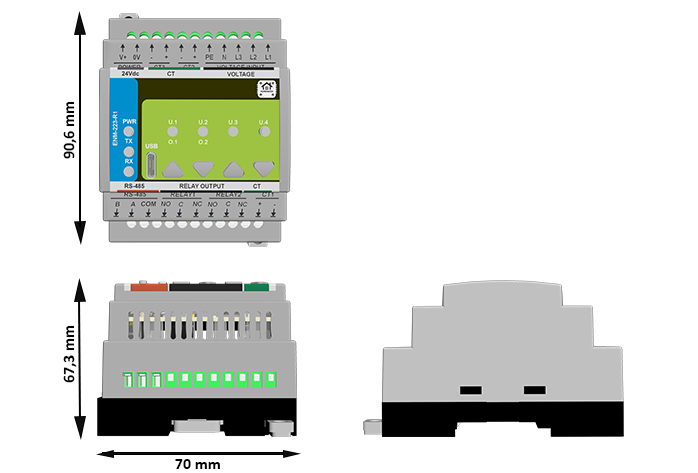
5.7 Mechanical Details
| Property | Specification |
|---|---|
| Mounting | DIN rail EN 50022 (35 mm) |
| Material / Finish | PC / ABS V-0, matte light gray + smoke panel |
| Dimensions (L × W × H) | 70 × 90.6 × 67.3 mm (9 division units) |
| Weight | ~420 g |
| Terminals | 300 V / 20 A / 26–12 AWG (2.5 mm²) / torque 0.5–0.6 Nm / pitch 5.08 mm |
| Ingress Protection | IP20 (EN 60529) |
| Operating Temp. | 0–40 °C / ≤95 % RH (non-condensing) |
ENM-223-R1 Physical Dimensions (DIN-rail enclosure)
5.8 Standards & Compliance
| Standard / Directive | Description |
|---|---|
| Ingress Rating | IP20 (panel mount only) |
| Altitude Limit | ≤ 2000 m |
| Environment | RoHS / REACH compliant |
6. Modbus RTU Communication
The ENM‑223‑R1 communicates over RS‑485 (Modbus RTU) and supports:
- Real-time metering via Input Registers
- Configuration via Holding Registers
- Control and acknowledgment via Coils
- Status monitoring via Discrete Inputs
The device acts as a Modbus Slave and can be polled by a PLC, SCADA, ESPHome, or Home Assistant system.
6.1 Addressing & Protocol Settings
| Setting | Value |
|---|---|
| Default Address | 3 (configurable: 1–255) |
| Baud Rate | 19200 8N1 (configurable) |
| Physical Layer | RS‑485 (half-duplex, A/B/COM) |
| Function Codes | 0x01, 0x02, 0x03, 0x04, 0x05, 0x06, 0x10 |
| Termination | External 120 Ω at bus ends |
| Fail-safe Bias | Required on master side |
📌 Use the WebConfig tool over USB‑C to set Modbus address and baud rate.
6.2 Input Registers — Real-Time Telemetry (FC04)
| Address | Type | Metric | Unit | Scaling |
|---|---|---|---|---|
| 100–102 | U16 | Voltage L1/L2/L3 | V | ×0.01 |
| 110–112 | U16 | Current L1/L2/L3 | A | ×0.001 |
| 200–207 | S32 | Active Power (L1–3, Totals) | W | 1 |
| 210–217 | S32 | Reactive Power (L1–3, Totals) | var | 1 |
| 220–227 | S32 | Apparent Power (L1–3, Totals) | VA | 1 |
| 240–243 | S16 | Power Factor L1–3, Total | – | ×0.001 |
| 244–246 | S16 | Phase Angle L1–3 | ° | ×0.1 |
| 250 | U16 | Frequency | Hz | ×0.01 |
| 251 | S16 | Temperature (internal) | °C | 1 |
6.3 Energy Registers (Wh/varh/VAh, FC04)
| Address | Type | Energy Type | Phase / Total | Unit |
|---|---|---|---|---|
| 300–307 | U32 | Active Energy (+ import) | A/B/C/Totals | Wh |
| 308–315 | U32 | Active Energy (− export) | A/B/C/Totals | Wh |
| 316–323 | U32 | Reactive Energy (+ inductive) | A/B/C/Totals | varh |
| 324–331 | U32 | Reactive Energy (− capacitive) | A/B/C/Totals | varh |
| 332–339 | U32 | Apparent Energy | A/B/C/Totals | VAh |
Energy values are 32-bit unsigned integers (Hi/Lo word pairs).
6.4 Holding Registers — Configuration (FC03/06/16)
| Address | Type | Description | Range / Units |
|---|---|---|---|
| 400 | U16 | Sample Interval | 10–5000 ms |
| 401 | U16 | Line Frequency | 50 or 60 Hz |
| 402 | U16 | Sum Mode | 0 = algorithmic 1 = absolute |
| 403 | U16 | Ucal Gain | 1–65535 |
| 410–420 | U16 | Ugain A/B/C | 16-bit |
| 421–431 | S16 | Uoffset A/B/C | 16-bit |
| 440–450 | U16 | Igain A/B/C | 16-bit |
| 451–461 | S16 | Ioffset A/B/C | 16-bit |
| 499 | U16 | Factory Reset Trigger | Write 1 to reset |
6.5 Coils — Output Control (FC01/05/15)
| Address | Description |
|---|---|
| 600 | Relay 1 Control (ON/OFF) |
| 601 | Relay 2 Control (ON/OFF) |
| 610–613 | Alarm Acknowledgment (L1–L3, Totals) |
6.6 Discrete Inputs — Read-only Status (FC02)
| Address | Description |
|---|---|
| 500–503 | LED Status (U.1–U.4) |
| 520–523 | Button Press (1–4) |
| 540–541 | Relay State (1–2) |
| 560–571 | Alarm/Warning/Event flags |
6.7 Scaling Summary
| Metric | Register Type | Scale Factor |
|---|---|---|
| Voltage (V) | Input Register | ÷100 |
| Current (A) | Input Register | ÷1000 |
| Power Factor | Input Register | ÷1000 |
| Frequency (Hz) | Input Register | ÷100 |
| Angle (°) | Input Register | ÷10 |
| Energy (Wh) | 32-bit Input | 1 |
6.8 Polling Best Practices
- Typical polling rate: 1 s for live data (powers, voltages, current)
- Energy: poll less often (e.g. every 5–10 s)
- Batch reads: Use FC04 and FC03 with multi-register reads for speed
- Avoid writing frequently to EEPROM-backed registers (e.g., Ucal or gains)
- Coils: Fast updates (e.g. overrides) okay; no debounce needed
🛠 To reduce bus collisions, stagger multiple ENMs on a shared RS‑485 bus using different poll intervals and address spacing.
6.9 Modbus Integration Example (MiniPLC)
modbus_controller:
  - id: enm223
    address: 3
    modbus_id: rtu_bus
    update_interval: 1s

sensor:
  - platform: modbus_controller
    modbus_controller_id: enm223
    name: "Urms L1"
    register_type: read
    address: 100
    value_type: U_WORD
    unit_of_measurement: "V"
    accuracy_decimals: 2
    filters:
      - multiply: 0.01

switch:
  - platform: modbus_controller
    modbus_controller_id: enm223
    name: "Relay 1"
    register_type: coil
    address: 600
7. ESPHome Integration Guide (MicroPLC/MiniPLC + ENM‑223‑R1)
The HomeMaster controller (MiniPLC or MicroPLC) running ESPHome acts as the Modbus RTU master over RS‑485. It polls one or more ENM‑223‑R1 modules and publishes all sensors, relays, LEDs, and alarms into Home Assistant.
No Home Assistant add-ons are required — all logic runs on the ESPHome controller.
7.1 Architecture & Data Flow
- Topology: Home Assistant → ESPHome (MicroPLC) → RS‑485 → ENM‑223‑R1
- Roles:
- ENM: metering, alarm rules, relays, LEDs, buttons
- ESPHome: Modbus polling, sensor/relay control, entity publishing
- HA: dashboards, energy view, automations
LED mappings, alarm logic, and override behavior are configured on the ENM module (via WebConfig). Home Assistant only reacts to exposed states.
7.2 Prerequisites (Power, Bus, I/O)
1. Power
- ENM: 24 V DC → V+ / 0V
- Controller: per spec
- If separate PSUs: share COM/GND between controller and ENM
2. RS‑485 Bus
- A—A, B—B (twisted pair), COM shared
- Terminate with 120 Ω resistors at both ends
- Default speed: 19200 baud, set in WebConfig
3. Field I/O
- Voltage inputs: L1, L2, L3, N, PE
- CTs: CT1–CT3 (1 V or 333 mV)
- Relays: dry contact, driven by internal logic or Modbus
- Buttons / LEDs: wired to MCU, mapped in firmware/UI
7.3 ESPHome Minimal Config (Enable Modbus + Import ENM Package)
uart:
  id: uart1
  tx_pin: 17
  rx_pin: 16
  baud_rate: 19200
  stop_bits: 1

modbus:
  id: rtu_bus
  uart_id: uart1

modbus_controller:
  - id: enm223_1
    address: 4
    modbus_id: rtu_bus
    update_interval: 1s

packages:
  enm223_1:
    url: https://github.com/isystemsautomation/HOMEMASTER
    ref: main
    files:
      - path: ENM-223-R1/Firmware/default_enm_223_r1_plc.yaml
        vars:
          enm_id: enm223_1
          enm_address: 4
          enm_prefix: "ENM #1"
7.4 Entities Exposed by the Package
Binary Sensors
- Relay states
- Button presses
- LED status
- Alarm conditions (Alarm / Warning / Event)
Sensors
- Urms, Irms L1/L2/L3
- Power (P, Q, S) totals
- Frequency, PF, Angle
- Energies: kWh, kvarh, kVAh (active/reactive/apparent)
Switches
- Relay 1/2 (Modbus coil 600/601)
- Acknowledge coils 610–613
- Override controls (force override toggle, hold-style)
Numbers (Optional)
- Sample interval
- Calibration gains (Ugain / Igain)
7.6 Using Your MiniPLC YAML with ENM
- Keep existing
uart:andmodbus:blocks - Add the
packages:block (as shown) and setenm_addressfrom WebConfig - Flash the controller — ESPHome discovers all sensors/entities automatically
- Add HA dashboard cards and
switchesfor relay, override, and ack actions
7.7 Home Assistant Setup & Automations
- Go to: Settings → Devices & Services → ESPHome → Add by hostname or IP
- Dashboard auto-discovers:
- Energies (for HA Energy view)
- Relays, buttons, LEDs
- Alarm states
- You can create:
- Energy Dashboard source:
VAh TotalorAP Total - Automation:
- Energy Dashboard source:
8. Programming & Customization
8.1 Supported Languages
- MicroPython
- C/C++
- Arduino IDE
8.2 Flashing via USB-C
- Connect USB-C to your PC.
- Enter boot/flash mode if required.
- Upload the provided firmware/source.
Boot/Reset combinations:
- Buttons 1 + 2 → forces the module into BOOT mode
- Buttons 3 + 4 → triggers a hardware RESET
These combinations are handled in hardware. Use them when flashing or manually rebooting the module.
🧭 Button layout reference:
8.3 Arduino IDE Setup
- Board Profile: Generic RP2350
- Flash Size: 2MB (Sketch: 1MB, FS: 1MB)
- Recommended Libraries:
#include <Arduino.h>
#include <SPI.h>
#include <SimpleWebSerial.h>
#include <Arduino_JSON.h>
#include <LittleFS.h>
#include <math.h>
#include <limits>
- Pin Notes:
- Buttons: GPIO22–25
- LEDs: GPIO18–21
- RS-485: MAX485, DE/RE control over TX
- USB: native, no UART bridge
8.4 Firmware Updates
- Upload via USB-C using Arduino IDE or PlatformIO
- Enter boot mode (Buttons 1 + 2)
- Upload
default_enm_223_r1.inofrom/firmware/ - Configuration is preserved (stored in LittleFS)
- Energy counters are safe (stored in FRAM)
9. Maintenance & Troubleshooting
| Symptom | Fix or Explanation |
|---|---|
| Relay won’t activate | May be in override; check relay logic mode |
| RS-485 not working | A/B reversed or un-terminated bus |
| LED doesn’t light up | Reassign in WebConfig or check GPIO18–21 |
| Button unresponsive | Test using WebConfig > Button state live |
| CRC Errors | Confirm baud, address, and wiring (A/B swap) |
| Negative Power Reading | Flip CT or check phase/CT alignment |
10. Open Source & Licensing
| Component | License |
|---|---|
| Hardware | CERN-OHL-W v2.0 |
| Firmware | GPLv3 |
| Config Tool | MIT |
11. Downloads
The following key project resources are included in this repository:
🧠 Firmware (Arduino/PlatformIO)
firmware/default_enm_223_r1.ino
Core firmware implementing Modbus RTU, alarm logic, relays, LED control, overrides, and WebConfig support.🧰 WebConfig Tool
tools/ConfigToolPage.html
HTML-based USB Web Serial interface for live configuration, calibration, alarm setup, and logic assignment.🖼 Images & UI Diagrams
Images/
Contains front-panel photos, system diagrams, wiring illustrations, and screenshots from WebConfig UI.📐 Hardware Schematics
Schematics/
Includes PDF schematics for Field Board and MCU Board — ideal for developers, reviewers, or third-party modders.📄 Datasheets & Manuals
ENM-223-R1 Datasheet.pdf
Covers full electrical and mechanical specs, terminal layout, block diagram, and pinout.📦 ESPHome YAML Templates
ENM223R1_ESPHome_Integration_Guide.md
Ready-to-usepackages:block for ESPHome controllers, with sensors, relays, alarms, override logic, and Home Assistant tips.
🔁 Latest releases can also be found in the Releases tab or in the
Firmware/directory.
12. Support
If you need help using or configuring the ENM‑223‑R1 module, the following support options are available:
🛠 Official Resources
🧰 WebConfig Tool (USB-C)
Configure the module directly from your browser — no drivers or software required.📘 Official Support Portal
Includes setup guides, firmware help, diagnostics, and contact form.
📡 Community & Updates
- 🔧 Hackster Projects — System integration, code samples, wiring
- 📺 YouTube Channel — Module demos, walkthroughs, and tutorials
- 💬 Reddit Community — Questions, answers, contributions
- 📸 Instagram — Visual updates and field applications