Nine metered circuits in four DIN modules
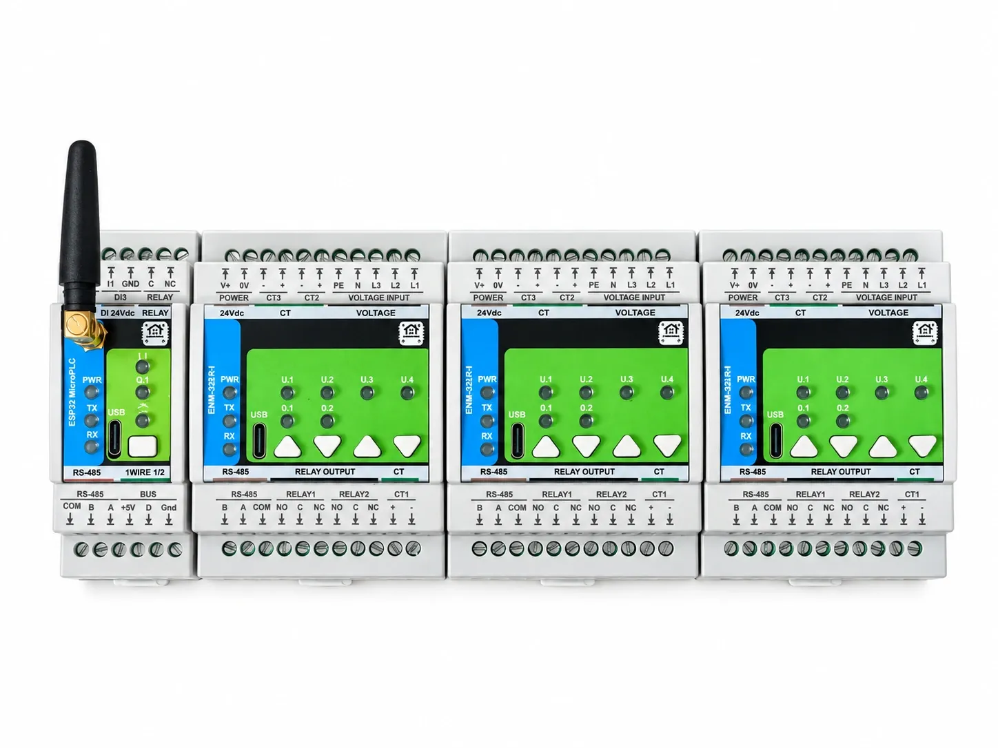
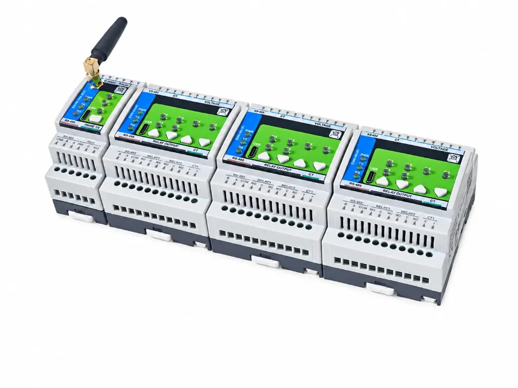
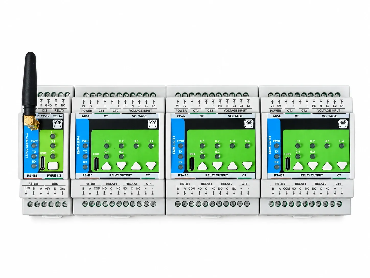
The 9-Channel Energy Metering Kit is everything needed to put circuit-level energy monitoring into an existing consumer unit: a MicroPLC controller, three ENM-223-R1 three-phase meters and nine 100 A split-core current transformers. Nine current channels, nine voltage channels and six relay outputs, four modules wide on the rail.
Everything is measured locally and arrives in Home Assistant over the native ESPHome API — no cloud account, no subscription, no MQTT broker and no hand-written Modbus register map. The meters keep measuring, and their relay logic keeps running, when the controller, the network or the Home Assistant server is unavailable.
Sized for a three-phase supply with a handful of circuits worth watching separately: an incomer on three channels, a large three-phase load on another three, and three single-phase branches — lighting, sockets, a compressor — on one channel each.
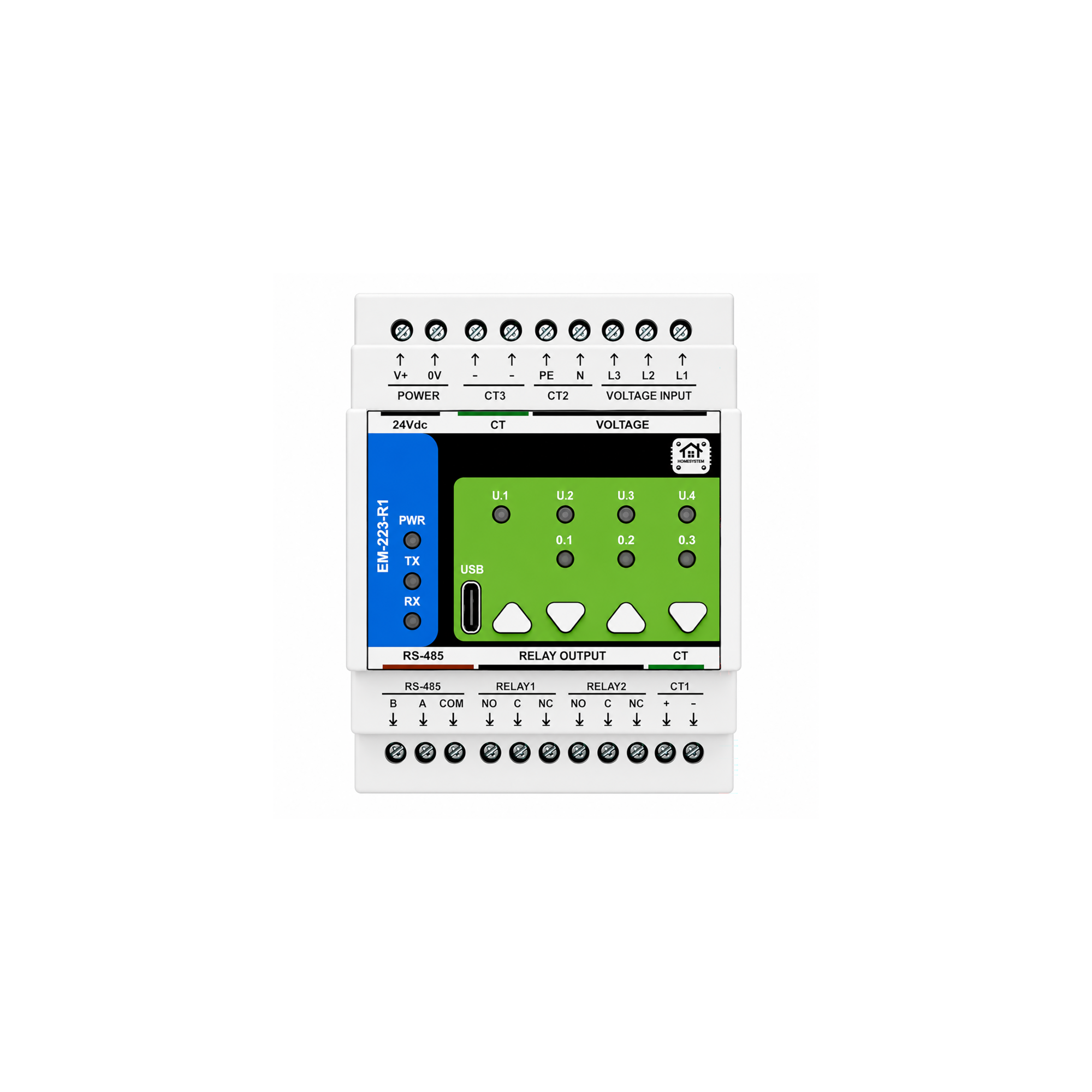
What is included
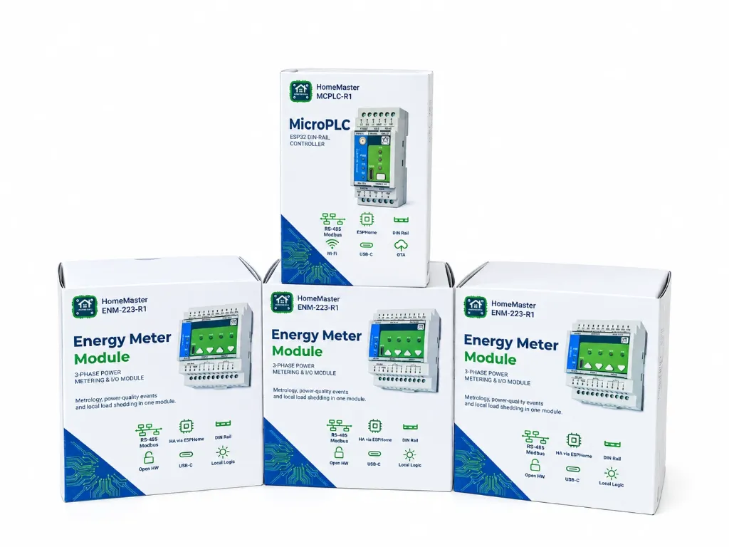
- 1 × HomeMaster MicroPLC — ESP32 DIN-rail controller, RS-485 Modbus RTU master, native Home Assistant API
- 3 × ENM-223-R1 three-phase energy meter — 3 voltage + 3 current channels each, 2 SPDT relays each
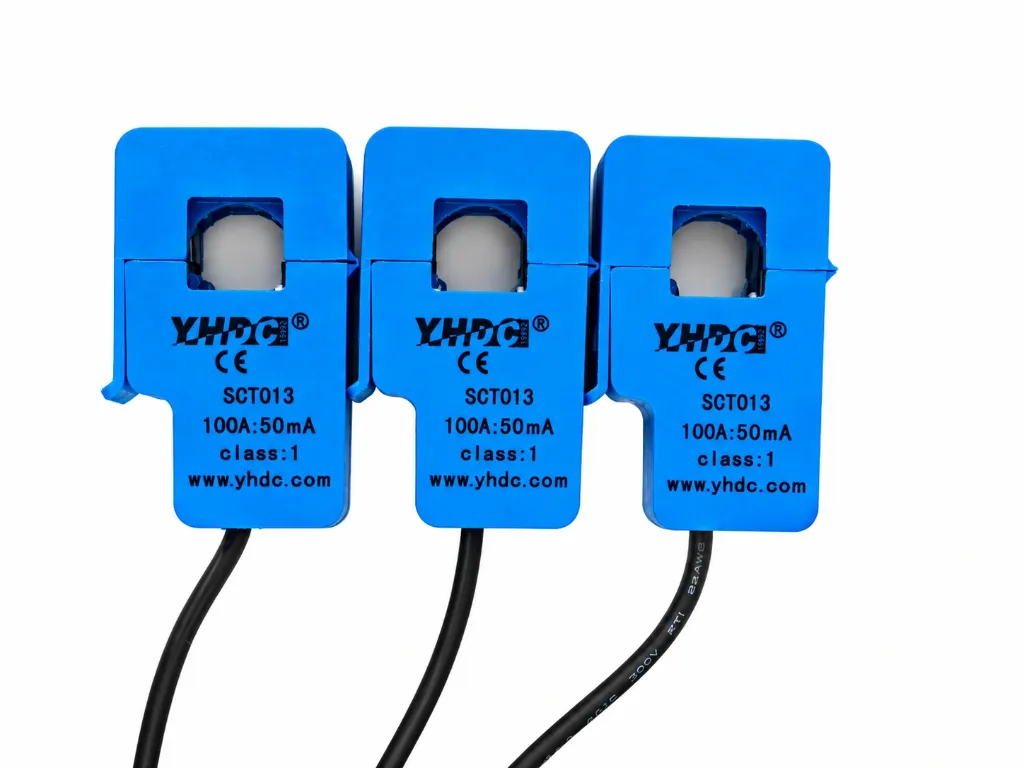
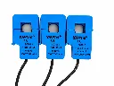
- 9 × split-core current transformer, 100 A, current-output, class 1
Not included: the 24 V DC supply, the MCB or fused terminals feeding the voltage-sensing inputs, RS-485 cable and the enclosure. These are specified by the panel, not by the kit.
What it measures
- RMS voltage and current per phase, plus neutral current
- Active, reactive and apparent power per phase and total
- Power factor per phase and total, line frequency, voltage–current angle
- Active and reactive energy, import and export, per phase and total
- THD per phase; sag, overvoltage, phase-loss, overcurrent and reverse-sequence flags
- Six dry-contact relay outputs driven by thresholds evaluated on the meters themselves
Why this kit rather than clamps and a cloud box
It keeps working with the server down
Each meter is an independent measuring device with its own processor. Alarm thresholds and relay actions are evaluated on the module, not in Home Assistant, so a load-shedding rule survives a controller reboot, a network outage or a server rebuild.
Real three-phase metering, not three single-phase clamps
Voltage is measured on every phase and multiplied by the current of the same phase inside the metering front end, so power factor, reactive power and direction of flow are real measurements rather than assumptions.
Four DIN modules for nine circuits
Twelve modules wide in total, sixteen with the controller — the usual limit in a retrofit is rail space, and that is what this kit is shaped around.
Open hardware, open firmware
Schematics, bill of materials and the Modbus register map are public; hardware under CERN-OHL-W v2, firmware and the ESPHome packages under MIT. Any Modbus RTU master can read the meters — HomeMaster controllers are convenient, not compulsory.
Planning the nine channels
| Module | Channels | Measures |
|---|---|---|
| Meter 1 | CT1, CT2, CT3 | Main incomer, one CT per phase |
| Meter 2 | CT1, CT2, CT3 | One large three-phase load — heat pump, machine, vehicle lift |
| Meter 3 | CT1, CT2, CT3 | Three single-phase branches, one per phase |
Inside the metering front end CT1 is multiplied by L1, CT2 by L2 and CT3 by L3. Three single-phase circuits on one module must therefore sit on three different phases. Put two of them on the same phase and that channel is computed against the wrong voltage — power factor and reactive power come out wrong, and no arithmetic in Home Assistant repairs it. Check the phases at the board with a phase tester before clamping anything.
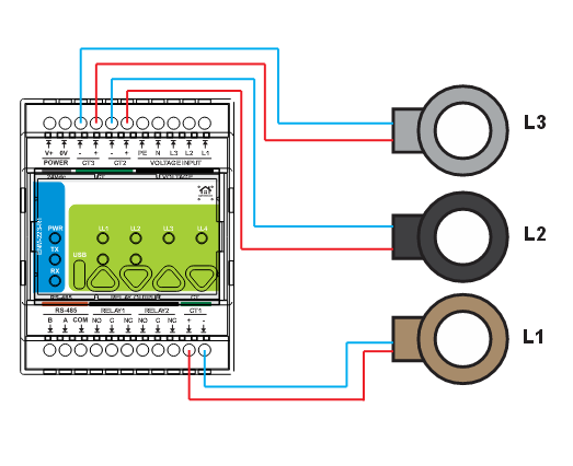
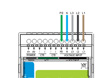
Wiring the kit
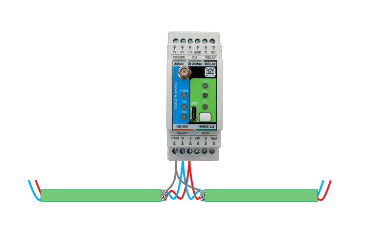
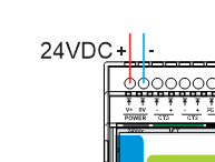
Three connections are common to the whole kit: the 24 V DC rail, the RS-485 bus and the voltage-sensing supply to each meter. The controller sits at one end of the bus, the three meters are daisy-chained from it, and COM is carried to every node.
Current-output CTs only, secondary ≤ 60 mA RMS — the nine transformers supplied with this kit are the right class. Voltage-output clamps of the 333 mV or 1 V class are a different device class and read wrong; a 1 A or 5 A secondary CT will damage the module. Never open a live CT secondary.
Home Assistant and ESPHome
The MicroPLC runs ESPHome and is the Modbus master. Each meter is added to its configuration as a ready-made package with its own prefix and Modbus address, and the entities appear in Home Assistant over the native ESPHome API within seconds — named, typed and with the right device classes for the Energy dashboard.
uart:
  id: uart_modbus
  tx_pin: 17
  rx_pin: 16
  baud_rate: 19200

modbus:
  id: modbus_bus
  uart_id: uart_modbus
  turnaround_time: 100ms
  send_wait_time: 250ms

packages:
  enm1:
    url: https://github.com/isystemsautomation/homemaster-dev
    ref: main
    files:
      - path: ENM-223-R1/Firmware/v0.2.0/default_enm_223_r1_plc/default_enm_223_r1_plc.yaml
    vars:
      enm_prefix: "ENM #1"
      enm_id: enm_1
      enm_address: 3
    refresh: 1d

  enm2:
    url: https://github.com/isystemsautomation/homemaster-dev
    ref: main
    files:
      - path: ENM-223-R1/Firmware/v0.2.0/default_enm_223_r1_plc/default_enm_223_r1_plc.yaml
    vars:
      enm_prefix: "ENM #2"
      enm_id: enm_2
      enm_address: 4
    refresh: 1d

  enm3:
    url: https://github.com/isystemsautomation/homemaster-dev
    ref: main
    files:
      - path: ENM-223-R1/Firmware/v0.2.0/default_enm_223_r1_plc/default_enm_223_r1_plc.yaml
    vars:
      enm_prefix: "ENM #3"
      enm_id: enm_3
      enm_address: 5
    refresh: 1d
ESPHome 2026.7.0 raised the Modbus client defaults — turnaround time from 100 ms to 600 ms and send wait time from 250 ms to 2000 ms. At the new defaults a bus with three meters becomes slow and one module can stop being polled with no error in the log. On 2026.7.0 and later set both values explicitly, as above.
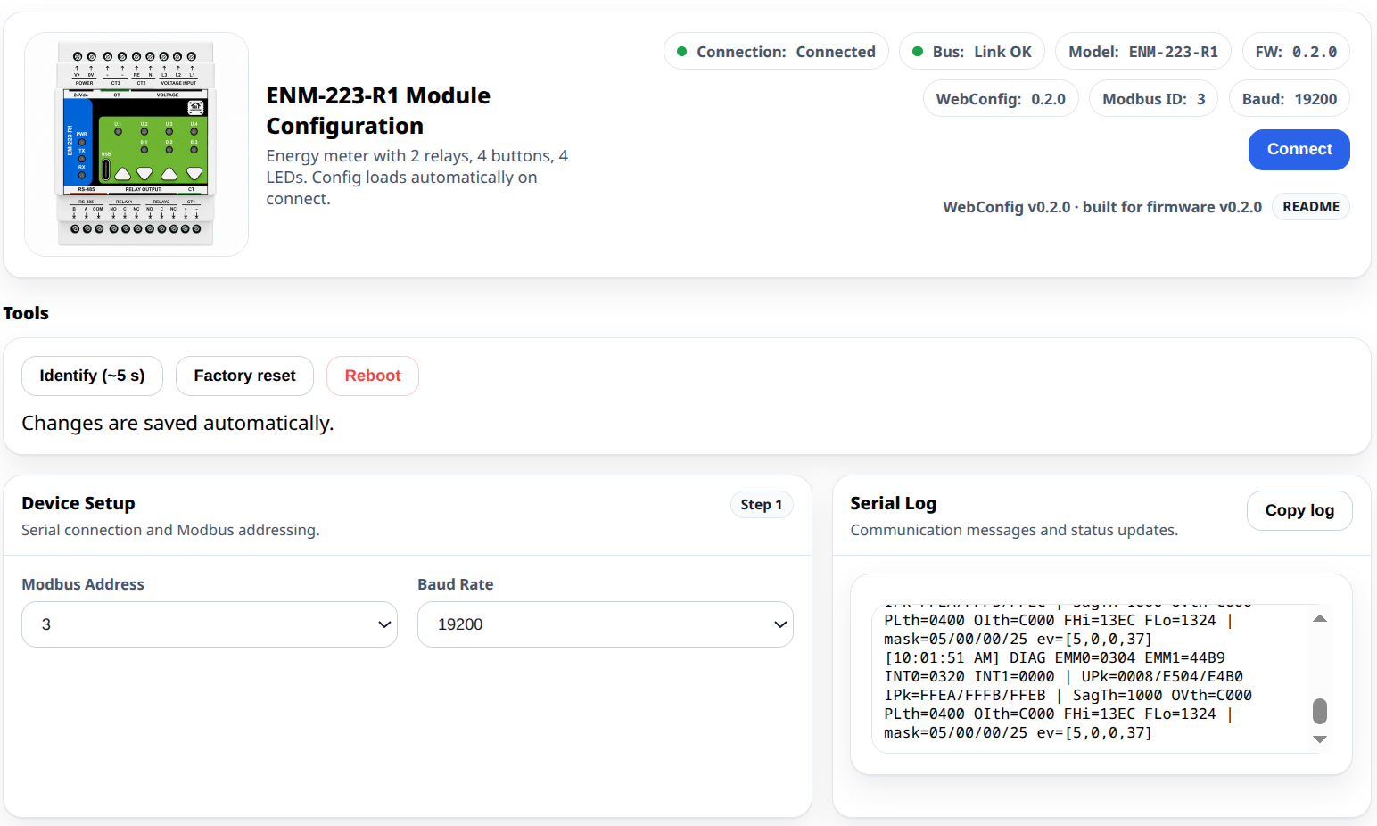
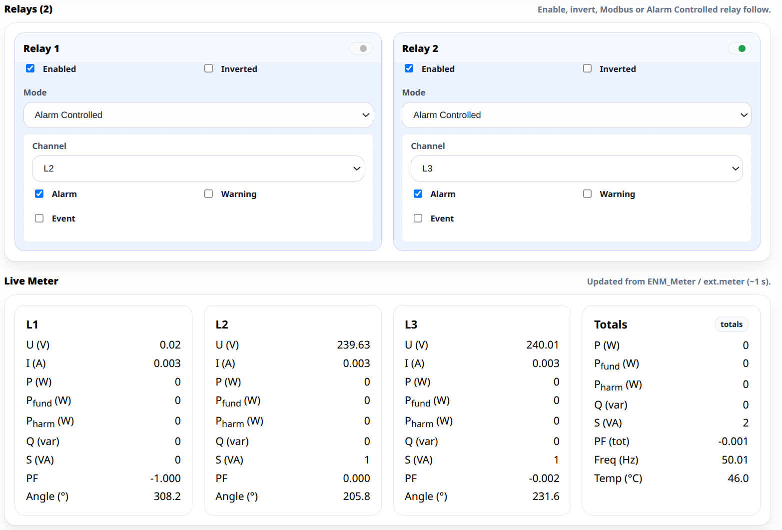
Each meter is given its own Modbus address in WebConfig over USB-C — a browser interface, no driver and no vendor application. Addresses 3, 4 and 5 are the convention used in the ready-made configuration.
To work out how many channels a particular panel needs and how wide it comes out, use the System Builder. The kit can be extended with further ENM-223-R1 meters on the same bus and the same controller.
Frequently asked questions
Can I meter nine separate single-phase circuits with this kit?
Yes, provided they are distributed across the three phases — three per phase. Each meter pairs CT1 with L1, CT2 with L2 and CT3 with L3, so the three channels of one module must be on three different phases. On a single-phase supply only one channel per module is usable and this kit is the wrong shape; ask us and we will size a different one.
Do I need the MicroPLC, or will my own controller do?
The meters are standard Modbus RTU slaves on RS-485, address 1–247, 9600–115200 baud, default 19200 8N1. Any Modbus master reaches them — a third-party PLC, a SCADA system, or an ESP32 of your own with an RS-485 transceiver. The MicroPLC is included because it is the shortest route to working entities in Home Assistant, with the packages already written.
Can it disconnect a load by itself?
Within its six relay channels, yes. Thresholds and acknowledgement behaviour are set in WebConfig and evaluated on the meter, so the rule runs with the bus master offline. The contacts are rated 3 A at 250 V AC resistive as a system limit and are not internally fused — switch anything larger through a contactor with its own protection, and fit external overcurrent protection.
Can I bill a tenant from these readings?
No. The meters are not certified revenue meters and carry no MID approval. The figures are for monitoring, diagnostics and automation. Where a reading has to hold up commercially, a certified meter is required and these modules sit alongside it.
What do I still have to buy?
A 24 V DC supply sized for the bus, protection for the voltage-sensing conductors, RS-485 cable (twisted pair plus a conductor for COM) and the enclosure. The kit covers the measuring and control hardware only.
Documentation
Both modules in this kit are open-source hardware. Schematics, firmware and the full Modbus register map are public.
Documents
| File | Description | Link |
|---|---|---|
| ENM-223-R1 integration guide | Register map, WebConfig and ESPHome packages | README.md |
| MicroPLC integration guide | Controller setup, RS-485 bus, ESPHome configuration | README.md |
| ENM-223-R1 datasheet | Technical specifications and electrical characteristics | ENM-223-R1_Datasheet.pdf |
Safety and installation notes
- Qualified personnel only. Installation by trained technicians familiar with SELV and mains wiring.
- Mixed voltage domains. 24 V DC is SELV; the voltage-sensing inputs are mains hazardous, 85–265 V AC.
- Install inside an IP20 control cabinet with a protective front plate over all module terminals and a closing door.
- Relay contacts: 3 A at 250 V AC resistive as a system limit, not internally fused — fit external overcurrent protection and use a contactor for larger loads.
- The alarm logic and relays are supplementary monitoring and control. They do not replace the protective devices an installation requires.
- Observe CT polarity and never open a live CT secondary.
Both modules are CE marked; ISYSTEMS AUTOMATION S.R.L. maintains the technical documentation and signed EU Declarations of Conformity, available on the individual product pages.
Related products
These other products might interest you