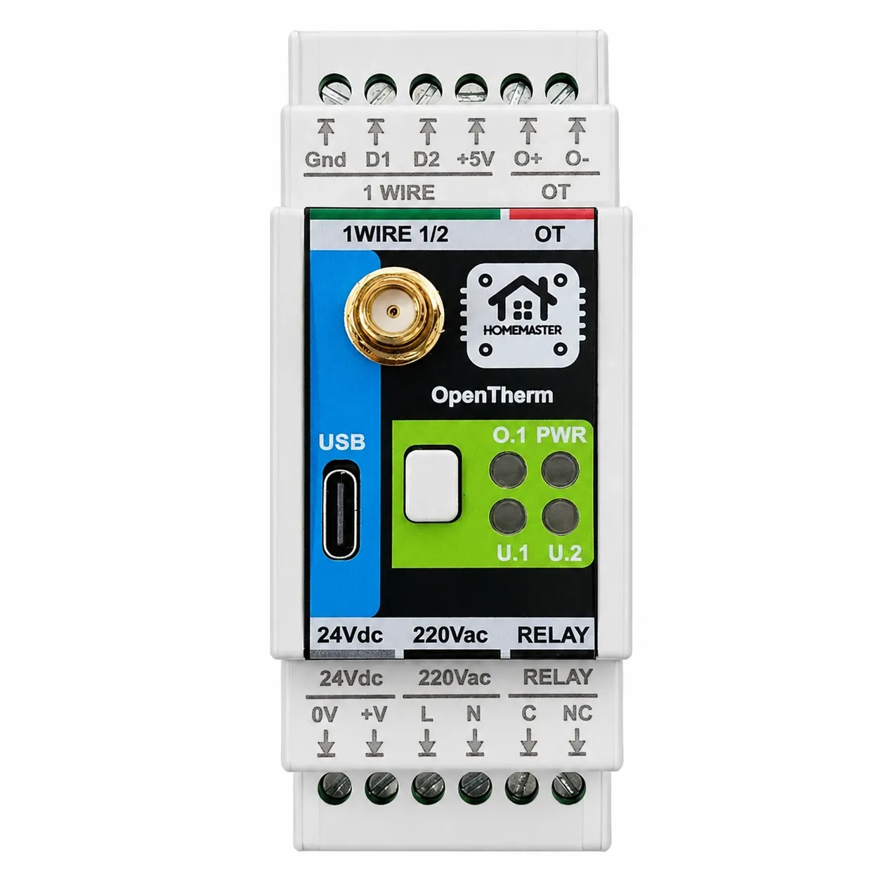
HomeMaster OpenTherm Gateway

OpenTherm or relay. Local control. No cloud. No lock-in.
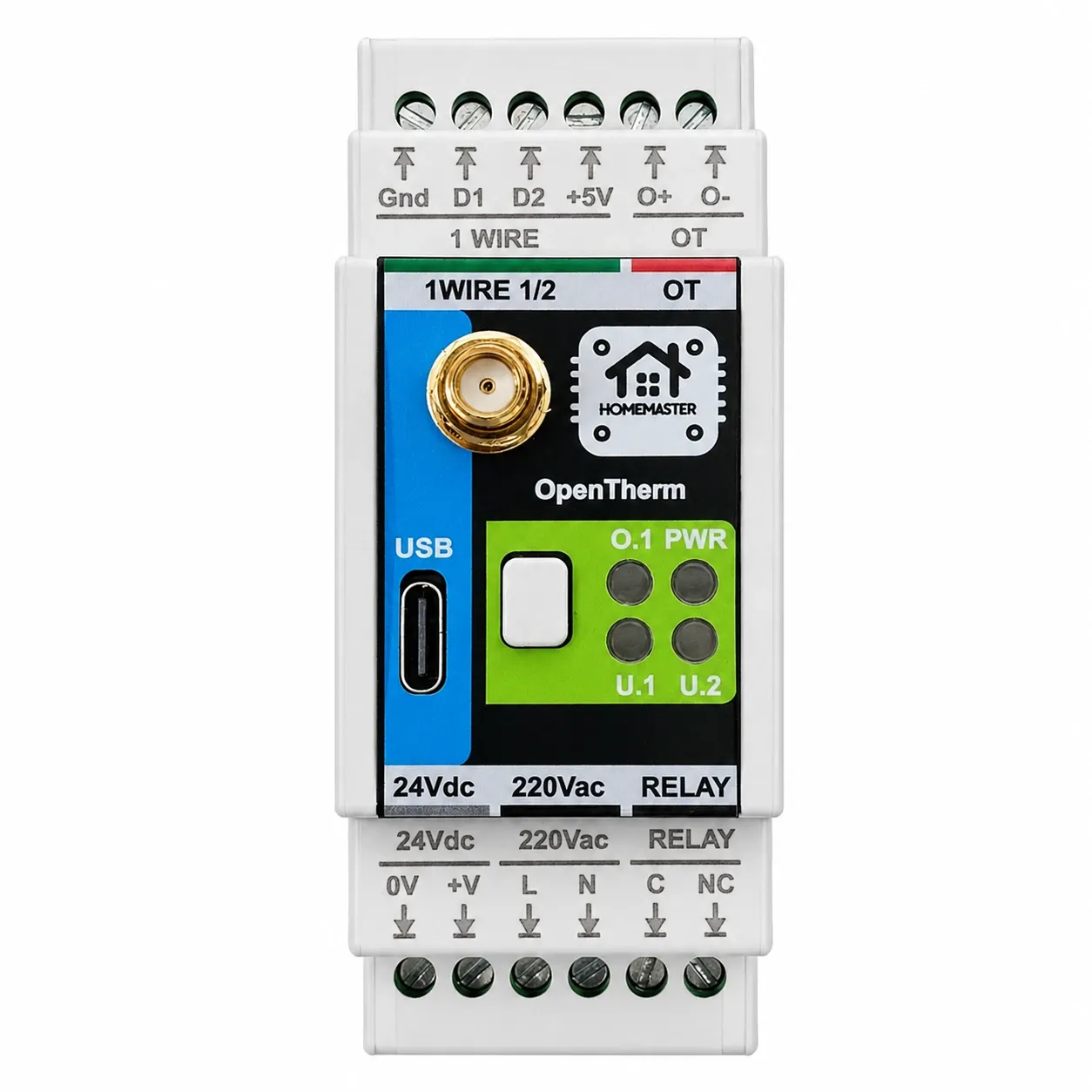
The HomeMaster OpenTherm Gateway is an open-source ESP32 heating gateway for modulating OpenTherm boilers or legacy on/off boilers via relay, with dual 1-Wire temperature inputs and fully local Home Assistant control.
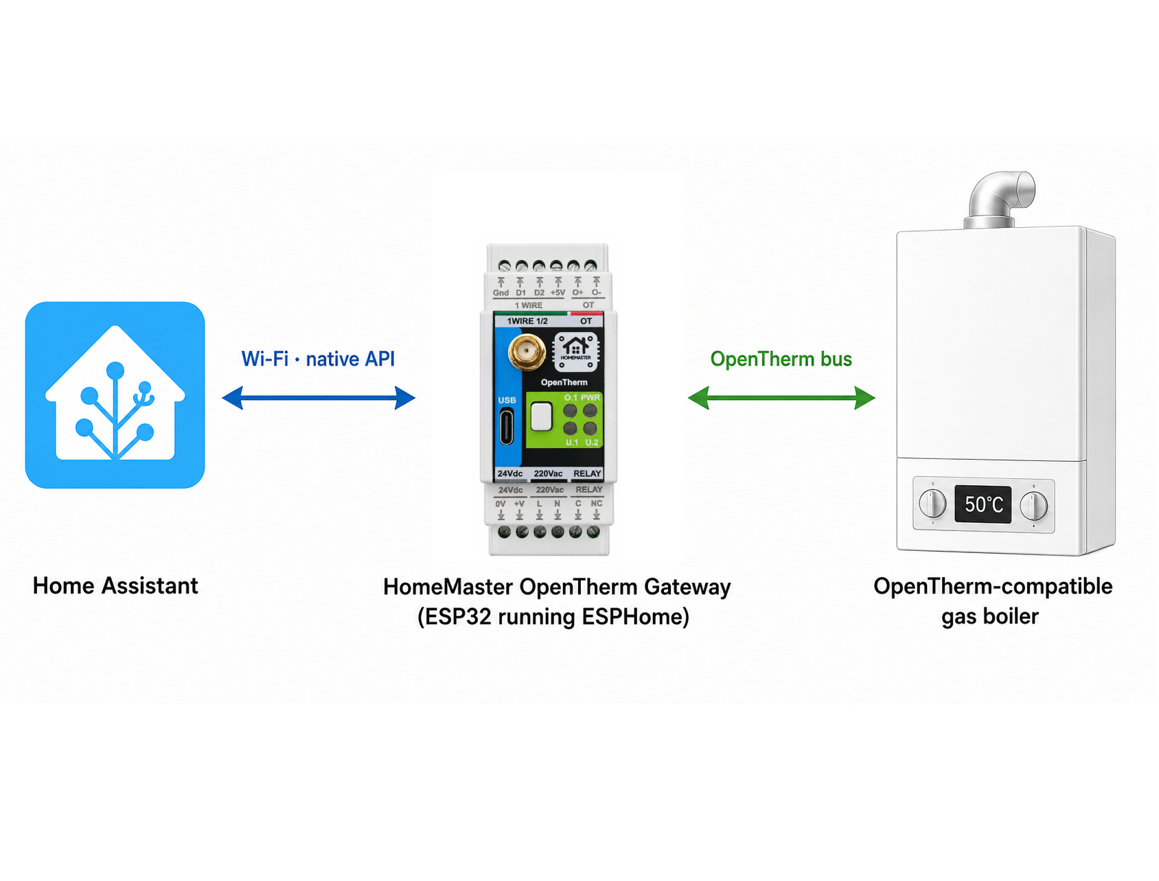
Integrates with Home Assistant over the native ESPHome API — no MQTT broker and no custom converters. The device appears in Home Assistant within seconds as ready-to-use entities, with low latency and no cloud.
Quick Overview
- OpenTherm interface — full boiler modulation, setpoints, fault monitoring and flame status
- Relay output — controls zone valves, pumps, 2-way and 3-way valves, or switches on/off boilers without OpenTherm
- Dual 1-Wire temperature inputs — monitor flow, return, buffer tank or room temperature
- Works with OpenTherm boilers (full modulation) and legacy on/off boilers (relay fallback)
- No cloud, no vendor lock-in — fully local control via Home Assistant
- Native Home Assistant integration via ESPHome
- Wide power input: 24 V DC or 85–265 V AC
- DIN-rail cabinet installation — professional grade
- Open hardware (CERN-OHL-W v2) + open firmware (MIT)
Typical Applications
- OpenTherm boiler modulation and setpoint control
- On/off boiler control via relay (no OpenTherm required)
- Zone valve or circulation pump switching
- Flow and return temperature monitoring via 1-Wire sensors
- Buffer tank temperature monitoring
- Boiler fault monitoring and alerting in Home Assistant
- Retrofit smart heating for any existing boiler system
- Custom heating automation without cloud dependency
Domestic Hot Water
The gateway controls hot water over OpenTherm the same way it controls heating. In Home Assistant you get a Boiler DHW Enable switch, a Boiler DHW Setpoint number (35–65 °C, 1 °C steps) and two sensors that are off by default until you enable them: Boiler DHW Temperature and Boiler DHW Flow Rate (l/min). A Boiler DHW Active binary sensor shows when the boiler is heating water.
With a combi boiler that is all you need: set the tap-water temperature from Home Assistant, turn hot water off while you are away, see when the boiler switches to DHW.
With a single-circuit boiler and an indirect cylinder the boiler stays in charge of the cylinder: it runs the 3-way valve, decides DHW priority and any anti-legionella cycle. The gateway sets the DHW setpoint and enable and reports what the boiler is doing. It does not drive the valve itself and has no dedicated cylinder sensor input — one of the two 1-Wire inputs is free for that if you want the cylinder temperature in Home Assistant.
When Home Assistant Is Down
The setpoints are ESPHome number entities that live on the gateway, not in Home Assistant. If Home Assistant is unreachable, the gateway keeps sending the last CH and DHW setpoints to the boiler and the boiler keeps heating. If the gateway itself loses power, the boiler stops receiving OpenTherm messages and falls back to its own panel, as the OpenTherm standard requires — it does not stop heating. The relay contact (C–NC) is closed when the gateway is unpowered, so a pump or valve wired to it stays energised.
What does not survive a Home Assistant outage: automations that recompute the setpoint, for example the weather-compensation curve from the build article. The last value they wrote stays in force. For a heating controller in winter this is the point: no cloud in the loop, and the boiler never depends on a server being up.
Which Boilers
Any boiler with an OpenTherm terminal. Boilers on eBus, Navien or other proprietary buses are not supported over OpenTherm. Boilers without OpenTherm can be switched on and off through the relay output — no modulation, but the same Home Assistant control. To see which OpenTherm data your boiler actually reports, run the OpenTherm scanner first.
Weather Compensation
The stock firmware exposes the CH flow setpoint; the outdoor-reset heating curve is added with the configuration from Weather-compensated heating with the OpenTherm Gateway. It needs an outdoor temperature source — a DS18B20 on one of the 1-Wire inputs, or a sensor from Home Assistant.
FAQ
Does the OpenTherm Gateway control hot water in Home Assistant?
Yes — DHW enable, DHW setpoint 35–65 °C, and DHW temperature and flow rate sensors.
Does it work with a single-circuit boiler and an indirect cylinder?
Yes. The gateway sets the DHW setpoint and enable; the boiler runs the cylinder, the valve and priority itself.
What happens to the boiler when Home Assistant is down?
The gateway keeps the last setpoints and the boiler keeps heating; if the gateway loses power the boiler falls back to its own panel.
Is there a failsafe?
The relay's NC contact is closed when the gateway is unpowered, and the boiler reverts to panel control without OpenTherm messages.
OpenTherm or a relay thermostat?
OpenTherm modulates the burner and sets the flow temperature; a relay only switches the boiler on and off. Use OpenTherm where the boiler has it, the relay where it does not.
Which boilers are compatible?
Any boiler with an OpenTherm terminal; eBus and proprietary buses are not.
Tech Specs
| Specification | Details |
|---|---|
| Architecture | Modular — MCU Board + Relay Board |
| Microcontroller | ESP32-WROOM-32U-N16 (dual-core, 16 MB flash) |
| Power Input | 24 V DC nominal (V+ / 0V) OR 85-265 V AC (L / N) |
| Relay Output* |
1 × SPDT relay (component), only C and NC terminals exposed externally — functionally SPST-NC. Rated load (system limit): 3 A @ 250 VAC (resistive); max 750 VA @ 250 VAC, 90 W @ 30 VDC. Relay output insulation from mains primary on the PCB is rated Basic per EN 62368-1; cross-phase/cross-source mains use is not permitted — see Relay Output Wiring section for full restriction. Relay components (informative only) rated up to 16 A @ 250 VAC (resistive); this rating does not apply to the complete module. |
| Typical Power Consumption | 3 W |
| Temperature Inputs | 2 x 1-Wire (DS18B20 compatible) |
| User Interface | 4 LEDs (PWR, O.1, U.1, U.2), 1 button |
| Wi-Fi | Wi-Fi 2.4 GHz (ESP32, pre-certified radio module) |
| OpenTherm Interface | 1 x OpenTherm bus (OT+ / OT-) with optocoupler isolation |
| USB | USB-C (ESD protected, CC detection, data to ESP32) |
Note: Relay outputs are not internally fused. External overcurrent protection must be provided according to applicable standards and installation requirements.
Installation, Environmental & Mechanical
| Category | Specification | Details |
|---|---|---|
| Terminal Specifications | Terminal type | Pluggable screw terminal blocks, 5.08 mm pitch |
| Terminal pitch | 5.08 mm | |
| Wire cross-section | 0.2–2.5 mm² (AWG 24–12) | |
| Conductor type | Solid or stranded copper | |
| Stranded wire | Ferrules recommended | |
| Tightening torque | 0.4 Nm (max) | |
| Environmental Ratings | Operating temperature | 0 °C to +40 °C (for unheated spaces, use a heated/conditioned control cabinet to keep ambient temperature within range) |
| Storage temperature | -10 °C to 55 °C | |
| Relative humidity | 0–90 % RH, non-condensing | |
| Ingress protection | IP20 (inside cabinet) | |
| Installation | Indoor control cabinet only; not for outdoor or exposed installation | |
| Terminal protection | All wiring terminals must be protected against accidental contact | |
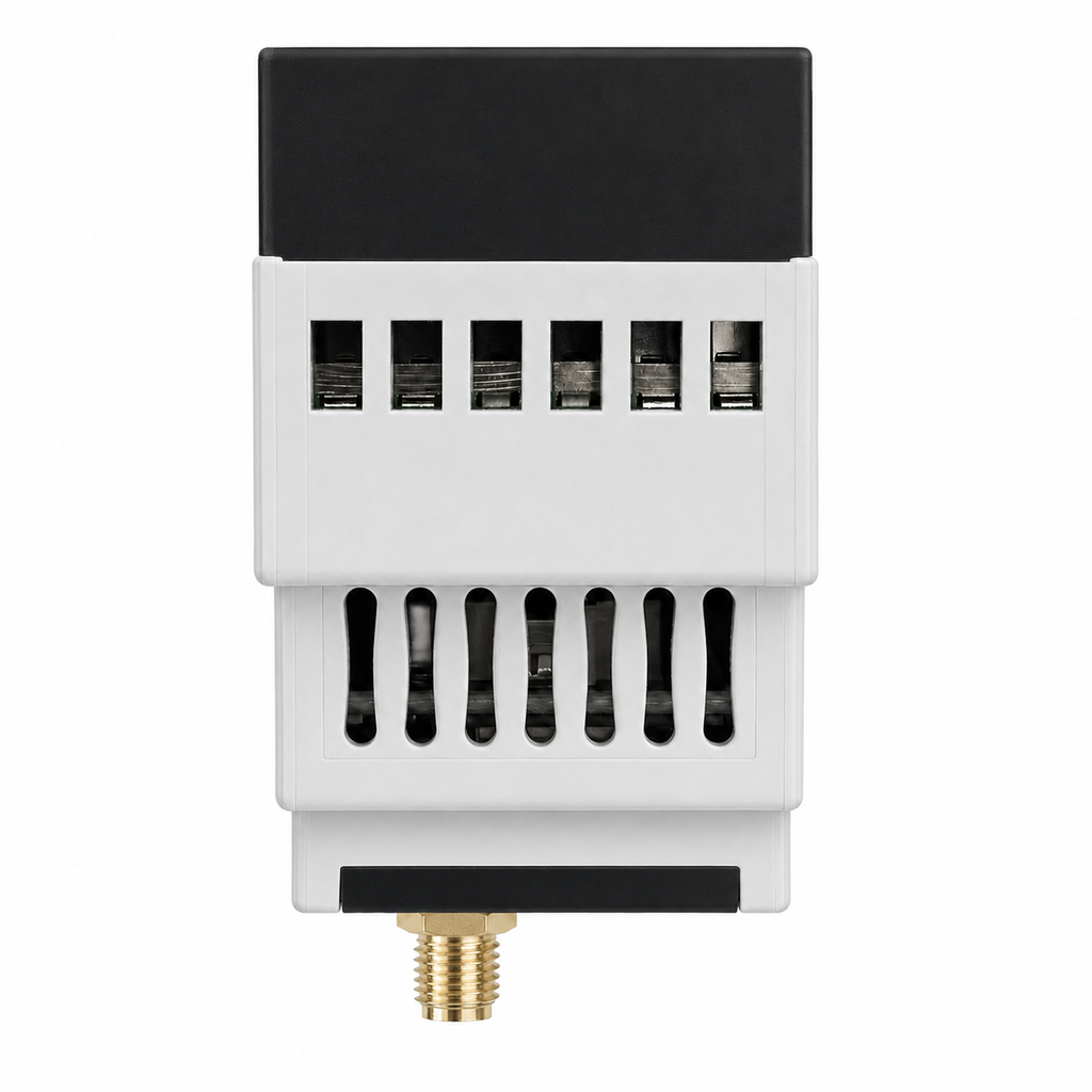
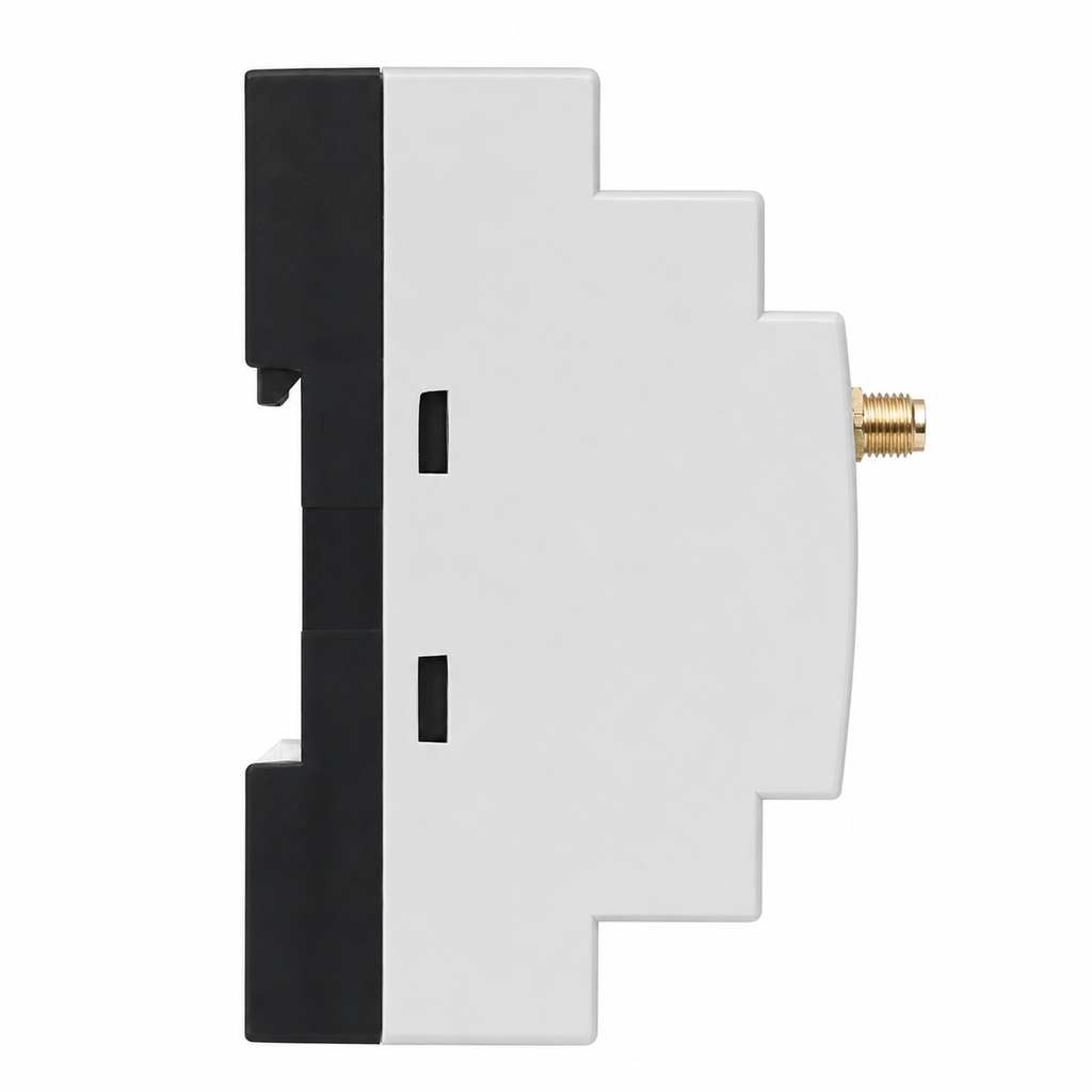
| Mechanical & Packaging | Product dimensions | 35.5 × 90.6 × 67.3 mm (L × W × H) |
| DIN width | 2 modules (2 × 17.5 mm) | |
| Mounting | 35 mm DIN rail | |
| Pack size | 140 × 96 × 95 mm (L × W × H) | |
| Mechanical drawing | Front + side views with DIN-clip depth | |
| Notes | All dimensions shown in millimeters unless stated otherwise |
Install only inside a control cabinet with ventilation; the cabinet must include a protective front plate covering all module connection terminals and a closing protective door; not for outdoor or exposed installation.
All wiring terminals must be protected against accidental contact by an insulating front plate, wiring duct, or terminal cover. Exposed live terminals are not permitted.
Home Assistant & ESPHome Integration
The OpenTherm Gateway comes with ESPHome pre-installed and supports direct integration with Home Assistant. Wi-Fi onboarding is available via Improv (USB Serial or BLE), without manual flashing for basic deployment.
Getting Started
Improv Wi-Fi Setup (Recommended)
- Mount & Power - Install on DIN rail and connect power input.
- Open Improv - Go to improv-wifi.com in Chrome or Edge.
- Connect Device - Use USB-C (serial) or Bluetooth LE.
- Enter Wi-Fi - Provide SSID and password, then connect.
- Auto Discovery - Device appears in Home Assistant / ESPHome Dashboard.
If Wi-Fi credentials change later, power-cycle the device to reopen the 15-minute provisioning window, then set new credentials with Improv (BLE or USB) at improv-wifi.com in Chrome or Edge.
One-Click Import (ESPHome Dashboard)
After Wi-Fi provisioning, click Take control in ESPHome Device Builder to import the official configuration from GitHub and establish the per-device API encryption key (firmware 1.1.0). Save the key — you will need it if you move the device to another Home Assistant instance.
From 1.1.0 the device accepts initial configuration for 15 minutes after power-on. When that window closes, power-cycle the device to reopen it. Until Home Assistant connects with the encryption key, status LED U.2 slow-blinks (expected — no API client yet).
⚠️ Note: After taking control, vendor-managed OTA updates will stop working
unless you keep the http_request, ota: platform: http_request,
and update blocks from the original configuration in your customised YAML.
If you remove these blocks, update via ESPHome OTA or USB instead.
Firmware / YAML Source
Official ESPHome configuration file: opentherm.yaml (GitHub)
Update manifest: manifest.json (GitHub)
- Native Home Assistant API integration
- OTA updates supported
- Improv setup via serial and BLE
- OpenTherm telemetry and control entities

The gateway is not an RS-485 device. It talks OpenTherm to the boiler and reaches Home Assistant over the network on its own, so it works with or without a MiniPLC or MicroPLC in the panel. To size a panel that also carries RS-485 modules, use the System Builder.
New to this kind of system? Two guides cover the ground: building a Home Assistant automation system and a wired ESPHome smart home. Two guides go deeper: weather-compensated heating and a full OpenTherm register scan.
Going deeper on this module: what still works when Home Assistant is down, wiring a new house before the walls close, weather-compensated heating, STR-3221-R1, AIO-422-R1 and the MiniPLC.
Documentation
The OpenTherm Gateway is open-source hardware. Design files, firmware, and documentation are publicly available.
Hardware Design Files
| File | Description | Link |
|---|---|---|
| Schematics | MCU and Field Board schematics | Schematics/ |
Compliance Documents
| File | Description | Link |
|---|---|---|
| EU Declaration of Conformity (DoC) | Signed EU Declaration of Conformity per Reg. (EC) 765/2008 and Decision 768/2008/EC | DoC_OTGW-R1.pdf |
| Datasheet | Technical specifications and electrical characteristics | OpenTherm_Datasheet.pdf |
Firmware & Software
| Resource | Description | Link |
|---|---|---|
| Default ESPHome Config | Official OpenTherm gateway YAML | opentherm.yaml |
| Integration Guide | Setup, wiring, and OpenTherm usage | README.md |
| Module Repository | Firmware and hardware source files | GitHub module folder |
Open-Source Hardware & Firmware
Hardware design files are licensed under CERN-OHL-W v2.
Firmware and ESPHome configuration are licensed under the MIT License.
Full source files are available on GitHub.
Connectors & terminal map
Top row (1 WIRE | OT)
| Pos | Label | Group | Function |
|---|---|---|---|
| 1 | Gnd | ONEWIRE | 1-Wire ground |
| 2 | D1 | ONEWIRE | 1-Wire bus 1 data |
| 3 | D2 | ONEWIRE | 1-Wire bus 2 data |
| 4 | +5V | ONEWIRE | 1-Wire sensor supply, max 50 mA |
| 5 | O+ | OT | OpenTherm bus positive |
| 6 | O- | OT | OpenTherm bus negative |
Bottom row (24Vdc | 220Vac | RELAY)
| Pos | Label | Group | Function |
|---|---|---|---|
| 1 | 0V | POWER_DC | 24 V DC return |
| 2 | +V | POWER_DC | 24 V DC input |
| 3 | L | POWER_AC | AC line 85-265 V (MAINS) |
| 4 | N | POWER_AC | AC neutral (MAINS) |
| 5 | C | RELAY | Relay common |
| 6 | NC | RELAY | Relay normally closed |
Ports & service interfaces
| Id | Type | Note |
|---|---|---|
| USB-C |
Housing notes
- No RS-485 bus. The gateway talks OpenTherm to the boiler and reaches the controller over the network.
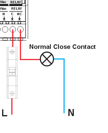
- Relay exposes C and NC only. There is no NO terminal and the contact is CLOSED when the relay is de-energised, so the load is powered by default.
- Two 1-Wire buses (D1, D2) share one Gnd and one +5V.
- The +5V rail is 50 mA - one third of the WLD and STR rails.
- Dual supply, 24 V DC or 230 V AC. Use one at a time.
Cabling and Wirings
Power Supply
The OpenTherm Gateway supports two input options: 24 V DC (V+ / 0V) or 85-265 V AC (L / N). Use only one power input method at a time.


Relay Output Wiring
⚠️ NC relay (reserve): The relay output is dry-contact and exposes only C and NC (no NO). When the device is unpowered or the relay is switched OFF, the NC contact is closed and the load is energized. This channel is a reserve for the installer — use it where equipment must switch on if the panel loses power. For failsafe-off loads (pumps, valves, heaters), use a module with NO/SPDT contacts (e.g. DIO-430-R1).
For boilers without OpenTherm, use the relay output to switch the boiler on/off. Also used to control zone valves, circulation pumps, or two-way and three-way valves.
The relay output exposes C and NC contacts only (normally-closed) and can be used to switch external actuators (zone valves, pumps, backup heaters) through proper external protection devices. System load limits: 3 A @ 250 VAC (resistive, system limit) · 750 VA @ 250 VAC maximum · 90 W @ 30 VDC maximum.
⚠️ External protection required: Relay output MUST be protected by external fuse or circuit breaker. Relay output is not internally fused.
⚠️ Relay output — use restriction (mandatory):
The relay output terminals (C, NC) shall be connected only to:
- the same mains supply circuit as the L/N input of this device, OR
- a SELV (Safety Extra-Low Voltage) circuit, OR
- a Limited Power Source (LPS) circuit per EN 62368-1.
Connection of the relay output to a different mains phase, an isolated mains source, or any circuit at a higher voltage class than the device's L/N input is not permitted. Failure to follow this restriction may cause dielectric breakdown between the device input and relay output circuits and presents electric-shock and fire hazards.
This restriction is required because the printed-circuit-board insulation between the L/N tracks and the C/NC tracks of the Relay board is rated as Basic per EN 62368-1 Table 11/14 (working voltage 250 V r.m.s.). Cross-mains use would require Reinforced insulation that the current hardware revision V1.0 does not provide. The next hardware revision will lift this restriction.
⚠️ Relay default state on power-up: The relay output is dry-contact and exposes only C and NC. When the device is unpowered or the relay is switched OFF, the NC contact is closed and the load is energized. Verify this is safe for your installation before connecting any boiler call-for-heat, pump, or valve to NC.
1-Wire Sensor Wiring
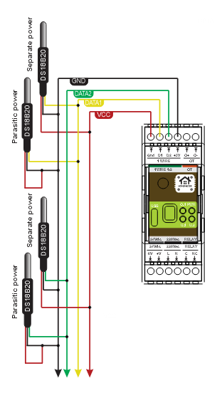
Use both 1-Wire buses to monitor multiple points — flow temperature, return temperature, buffer tank, or room sensors. Works independently of the boiler type.
Two independent 1-Wire channels are available for DS18B20-compatible temperature sensors. Use daisy-chain (bus) topology only — star wiring is not supported. Keep sensor stubs ≤ 0.5 m. See Cable Recommendations below for full wiring guidance.
⚠️ One sensor per bus by default. The shipped configuration does not pin sensor addresses.
With multiple sensors on the same 1-Wire bus, ESPHome reads the first sensor it discovers — assignment is non-deterministic across reboots.
For multiple sensors per bus, set explicit address: values in YAML (visible in ESPHome logs at boot).
OpenTherm Bus Wiring
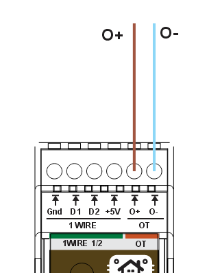
Connect OT+ and OT− to the boiler OpenTherm interface for full modulation control, setpoint management, fault monitoring and flame status reporting in Home Assistant.
Keep OT wiring separated from high-voltage conductors.
Cable Recommendations & Shield Grounding
General Routing Rules
- Route low-level signal cables (1-Wire/OT) separately from mains, relay output wiring, contactors, and power wiring.
- If crossing power cables is unavoidable, cross at 90 degrees.
- Keep cable runs as short as practical and avoid long parallel runs with high-current conductors.
Temperature Cable (1-Wire)
- Recommended: shielded 3-core (+5V / DATA / GND).
- High-EMI / long runs: shielded pairs + overall shield (e.g., LI2YCY PiMF 2x2x0.50).
- Keep sensor stubs ≤ 0.5 m. Use daisy-chain (bus) topology only — star wiring is not supported.
OpenTherm Cable
- Use twisted pair cable for OT+ / OT-.
- Overall shield recommended in industrial/noisy cabinets.
- Recommended cable types: J-Y(ST)Y 2×2×0.5 mm² or LI2YCY PiMF 2×2×0.50.
Shield Grounding
- Default recommendation: bond cable shield(s) to cabinet PE/EMC ground at controller side only.
- Do not connect shields directly to signal terminals (1-Wire/OT).
- If both ends are equipotential bonded cabinets, both-end shield bonding may be used with proper 360-degree clamps.
System Architecture & Pinout


Safety and Installation Notes
- Disconnect all power before installation or wiring changes.
- Use only one power input method at a time (24 V DC or AC L/N input).
- Install only inside a closed control cabinet; protect all terminals from accidental contact.
- Use external overcurrent protection (fuse/breaker) for relay circuits and mains inputs.
- Relay outputs are not internally fused; use external contactors for loads above 3 A and for high inrush/inductive loads.
- Relay output use restriction: terminals C and NC shall be connected only to the same mains supply as L/N, or to SELV / Limited Power Source circuits. Cross-phase or cross-source mains connection is not permitted with hardware revision V1.0.
- L / N terminals may carry hazardous voltage; installation by qualified personnel only.
- Follow local electrical code and boiler manufacturer OpenTherm wiring requirements.
Compliance & Certifications
The OpenTherm Gateway module is CE marked. ISYSTEMS AUTOMATION S.R.L. (HomeMaster® brand) maintains the technical documentation and a signed EU Declaration of Conformity (DoC) available for download in the Documents and Resources section above.
- EMC Directive 2014/30/EU — EN 55032:2015 (Class B emissions), EN 55035:2017 (immunity), tested by Idvorsky Laboratories Ltd. (Job #1648)
- Low Voltage Directive 2014/35/EU — EN 62368-1:2020 + A11:2020, in-house dielectric and isolation testing by ISYSTEMS AUTOMATION compliance laboratory
- RoHS Directive 2011/65/EU — EN IEC 63000 technical documentation
- HomeMaster® — registered EU trademark (EUTM No. 019082911, EUIPO, registered 15 January 2025)
Build Guides & Tutorials
Step-by-step projects built with the OpenTherm Gateway.

Drive the boiler's water temperature from an outdoor-reset curve, trimmed by a room thermostat.

Sweep all 256 Data-IDs to map what your boiler exposes, including undocumented OEM registers.
A relay thermostat gives Home Assistant one command: heat, or don't.
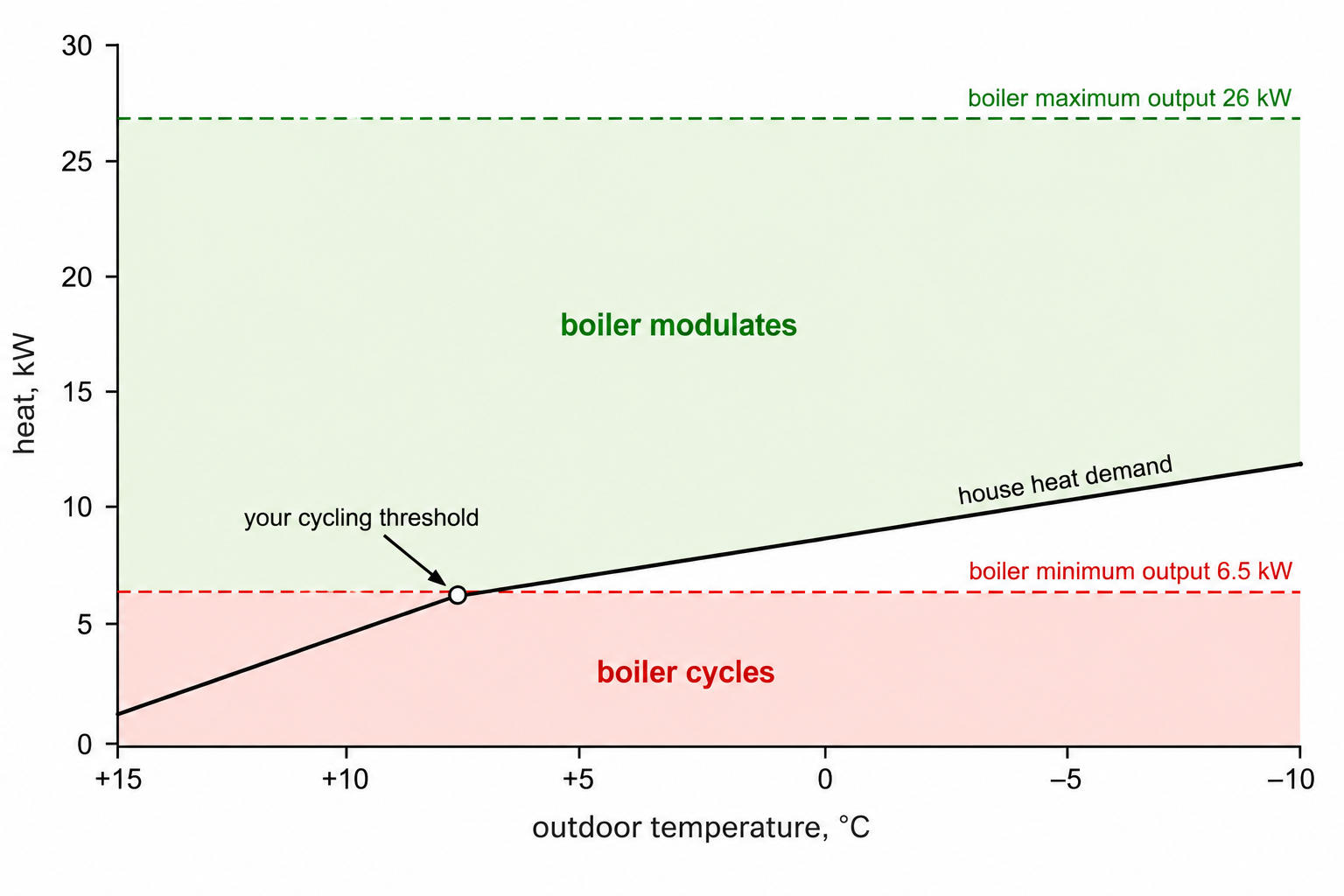
People put a boiler on OpenTherm, connect it to Home Assistant, and in October the burner still starts every few minutes.
OpenTherm® is a registered trademark of The OpenTherm Association. ISYSTEMS AUTOMATION S.R.L. (HomeMaster®) is not affiliated with or certified by the Association; the name is used for compatibility reference only.
Related products
These other products might interest you