
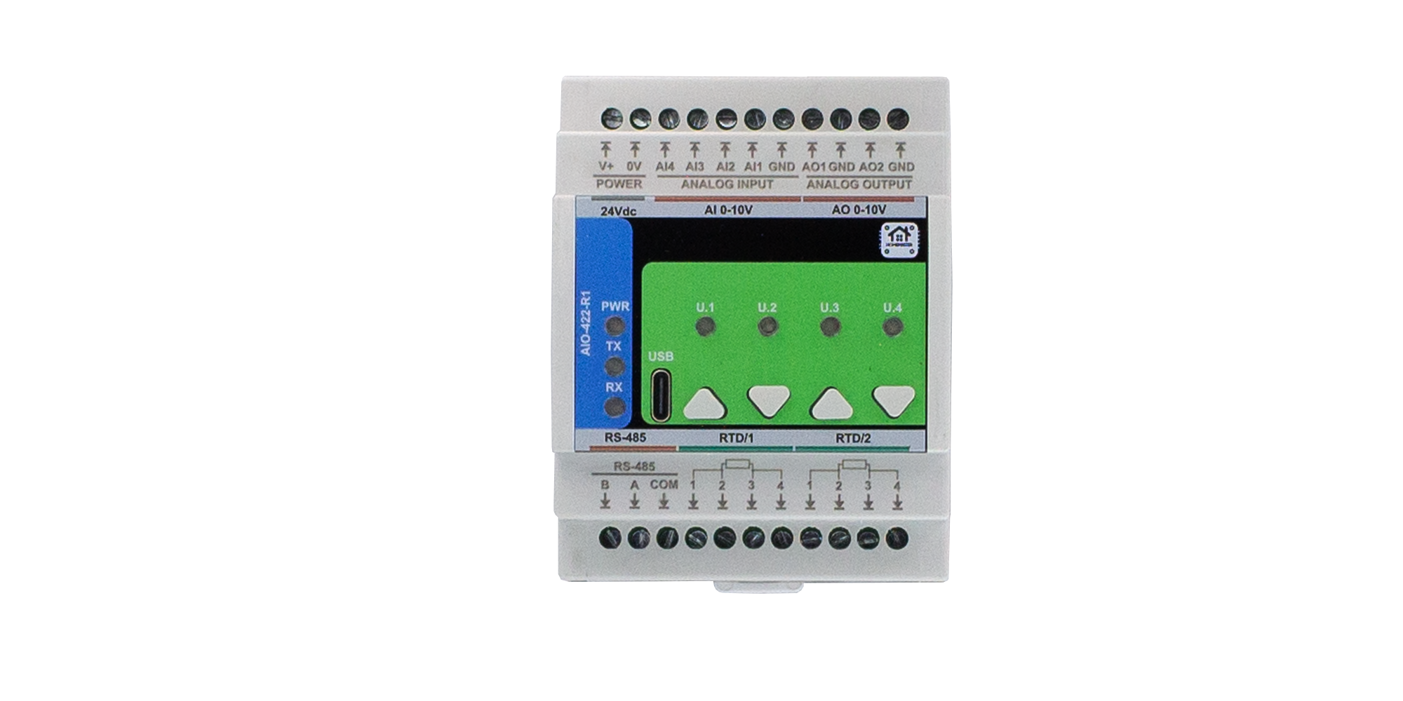
HomeMaster AIO-422-R1
The HomeMaster AIO-422-R1 is a DIN-rail mixed-signal expansion module for analog sensing and control with RTD temperature inputs. It provides 4 analog voltage inputs (0–10 V), 2 analog voltage outputs (0–10 V), and 2 RTD channels (PT100/PT1000 via MAX31865).
The module is a Modbus RTU slave over RS-485 and is configured via USB-C WebConfig using Web Serial. All configuration is stored persistently.
Quick Overview
- High-precision analog I/O for automation and smart home systems
- 4 × analog inputs (0–10 V) with 16-bit ADC (ADS1115)
- 2 × analog outputs (0–10 V) with 12-bit DAC (MCP4725A0)
- 2 × RTD inputs (PT100/PT1000) with MAX31865 (2/3/4-wire support)
- RS-485 Modbus RTU multi-drop communication (half-duplex)
- USB-C setup and firmware/configuration via Web Serial (WebConfig)
- DIN-rail enclosure with protected terminals (IP20, inside cabinet)
Typical Applications
- 0–10 V HVAC control, dampers, and pump speed interfaces
- Analog pressure/level sensors (0–10 V) and environmental monitoring
- RTD temperature monitoring for boilers, heat exchangers, and tanks
- Industrial cabinet automation and SCADA-ready analog telemetry
- ESPHome + Home Assistant control using Modbus polling on the controller
Tech Specs
| Specification | Details |
|---|---|
| Microcontroller | RP2350A dual-core microcontroller |
| Storage | External QSPI flash (32 Mbit) |
| Power input | 24 V DC nominal (recommended range 18–30 V DC); includes reverse polarity protection and surge protection |
| Analog inputs | 4 × voltage inputs, 0–10 V nominal range; ADC ADS1115, 16-bit resolution; input impedance >100 kΩ |
| Analog outputs | 2 × voltage outputs, 0–10 V nominal range; DAC MCP4725A0, 12-bit resolution; recommended max output current 10 mA per channel |
| RTD inputs | 2 × PT100/PT1000 (supports 2-, 3-, or 4-wire); interface MAX31865; 15-bit temperature resolution |
| Communication | RS-485 half-duplex Modbus RTU (MAX485) with surge protection and fail-safe biasing |
| USB | USB-C, 5 V logic, ESD protected (configuration and firmware update) |
| Power consumption | Typical 0.2–0.4 W; maximum module power consumption approx. 1 W |
| Terminal type | Pluggable screw terminal blocks, 5.08 mm pitch |
| Wire cross-section | 0.2–2.5 mm² (AWG 24–12) |
| Tightening torque | 0.4–0.6 Nm |
| Operating temperature | 0 °C to +40 °C |
| Storage temperature | −10 °C to +55 °C |
| Relative humidity | 0–90 % RH, non-condensing |
| Ingress protection | IP20 (inside cabinet only) |
| Max altitude / Pollution | 2000 m / Pollution degree 2 |
| Modbus address / Baud | 1–255; typically default address 3 and baud range 9600–115200 (set via WebConfig) |
Installation, Environmental & Mechanical
| Category | Specification | Details |
|---|---|---|
| Terminal Specifications | Terminal type | Pluggable screw terminal blocks, 5.08 mm pitch |
| Wire cross-section | 0.2–2.5 mm² (AWG 24–12) | |
| Conductor type | Solid or stranded copper | |
| Stranded wire | Ferrules recommended | |
| Tightening torque | 0.4–0.6 Nm | |
| Terminal access | Install in a control cabinet; protect against accidental contact | |
| Environmental Ratings | Operating temperature | 0 °C to +40 °C |
| Storage temperature | −10 °C to +55 °C | |
| Relative humidity | 0–90 % RH, non-condensing | |
| Ingress protection | IP20 (inside cabinet) | |
| Max altitude | 2000 m | |
| Pollution degree | 2 | |
| Mechanical & Packaging | Product dimensions | 71.5 × 90 × 59 mm (L × W × H) |
| DIN units | 4 division units (≈ 72 mm DIN rail mounting width) | |
| Mounting | 35 mm DIN rail (EN 50022) | |
| Enclosure | PC/ABS, UL94-V0 | |
| Net weight | TBD | |
| Gross weight | TBD + 98 g (packing) | |
| Pack size | 140 × 125 × 94 mm (L × W × H) |
Install only inside a control cabinet with ventilation; the cabinet must include a protective front plate covering all module connection terminals and a closing protective door; not for outdoor or exposed installation.
All wiring terminals must be protected against accidental contact by an insulating front plate, wiring duct, or terminal cover. Exposed live terminals are not permitted.
Home Assistant / Modbus / Web Config Integration
The AIO-422-R1 supports flexible integration with:
- HomeMaster MicroPLC / MiniPLC controllers as Modbus RTU masters
- PLC and SCADA systems via RS-485 Modbus RTU
- Home Assistant via ESPHome on the controller (entities from Modbus registers)
- Direct USB-C configuration using browser-based WebConfig
Configuration is saved persistently and restored at power-up.
Quick Setup Process (USB-C WebConfig)
- Mount & Power — mount on DIN rail and connect 24 V DC.
- Connect USB-C — attach USB-C to your PC.
- Open WebConfig — open the WebConfig page in Chrome or Edge.
- Connect Device — click Connect and select the serial device.
- Configure Modbus — set address and baud rate.
- Configure I/O behavior — analog input scaling, analog output setpoints, RTD wiring mode (2/3/4-wire).
- Save & Disconnect — save settings and disconnect USB-C.
Register-level and entity mapping details are available in the AIO-422-R1 README.
Minimal ESPHome YAML (Controller side)
Use this on the MiniPLC/MicroPLC (ESPHome). It enables the RS-485 bus and imports a ready-made AIO package.
uart:
  id: uart_modbus
  tx_pin: 17
  rx_pin: 16
  baud_rate: 19200
  parity: NONE
  stop_bits: 1

modbus:
  id: modbus_bus
  uart_id: uart_modbus

packages:
  aio1:
    url: https://github.com/isystemsautomation/HOMEMASTER
    ref: main
    files:
      - path: AIO-422-R1/Firmware/default_aio_422_r1_plc/default_aio_422_r1_plc.yaml
        vars:
          aio_prefix: "AIO#1" # shown in Home Assistant entity names
          aio_id: aio_1      # internal unique id
          aio_address: 3     # Modbus address set in WebConfig
    refresh: 1d
`aio_address` must match the Modbus address configured in WebConfig.
Documentation
The AIO-422-R1 is open-source hardware. Hardware, firmware, and integration files are available in the HomeMaster repository.
Hardware Design Files
| File | Description | Link |
|---|---|---|
| Field Board Schematic | Analog inputs/outputs and RTD front-end | AIO-422-R1-FieldBoard.pdf |
| MCU Board Schematic | Controller, RS-485, USB-C, power conversion | AIO-422-R1-MCUBoard.pdf |
| Datasheet | Full electrical, mechanical, and compliance summary | AIO-422-R1_Datasheet.pdf |
Firmware & Software
| Resource | Description | Link |
|---|---|---|
| Firmware Source Code | Firmware and configuration tools | GitHub repository |
| Integration Guide | Setup and configuration documentation | README.md |
| WebConfig Tool | Browser-based configuration interface (USB-C Web Serial) | Built-in USB interface |
Cabling and Wirings
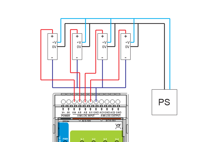
24 V DC Supply (V+ / 0V)
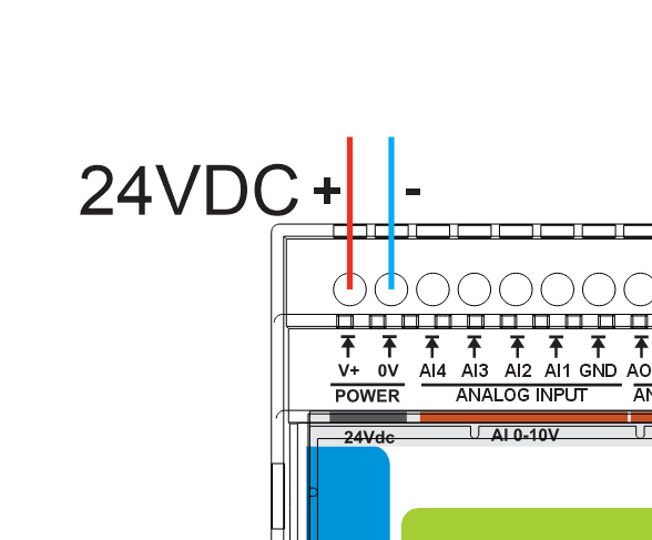
- Use a regulated 24 V DC SELV supply
- Apply upstream fuse protection according to cabinet rules
- Keep power wiring separated from low-level analog/RTD cabling
Analog Inputs (AI1–AI4, 0–10 V)
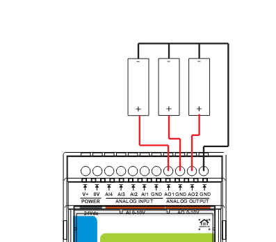
Analog Outputs (AO1–AO2, 0–10 V)
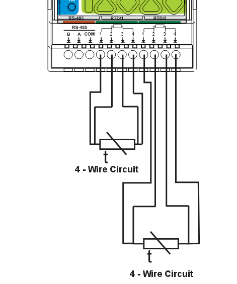
RTD Inputs (RTD1 / RTD2, PT100/PT1000)
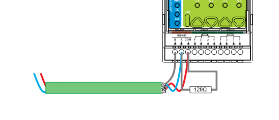
RS-485 Modbus (A / B / COM)
Cable Recommendations & Shield Grounding
General routing rules
- Route low-level signal cables (analog and RTD) separately from power and high-current conductors
- If crossing power cables is unavoidable, cross at 90°
- Keep cable runs as short as practical and avoid parallel runs with high-current wiring
- Label cables and provide strain relief at terminals
Analog (0–10 V) cable
- Use twisted pair (Signal + AGND) per analog channel
- Use overall shielding for typical installs, or individually shielded pairs for high-EMI environments
- Examples: J-Y(ST)Y (overall shield) or LI2YCY PiMF (shielded twisted pairs)
RTD temperature cable
- Recommended: shielded cable for RTD (PT100/PT1000), using 2/3/4-wire wiring as required
- Shielded pairs are recommended for best accuracy (especially for 4-wire)
- Example: J-Y(ST)Y (overall shield) or LI2YCY PiMF (pairs)
RS-485 (Modbus) cable
- Use twisted pair for A/B (characteristic impedance 120 Ω recommended)
- Prefer shielded cable in industrial/noisy panels
- Use an additional conductor/pair as COM reference if required by the RS-485 network design
Shield grounding
- Bond cable shield(s) to cabinet PE/EMC ground at the PLC/controller end only by default
- Do not connect shields directly to signal terminals (A/B/COM)
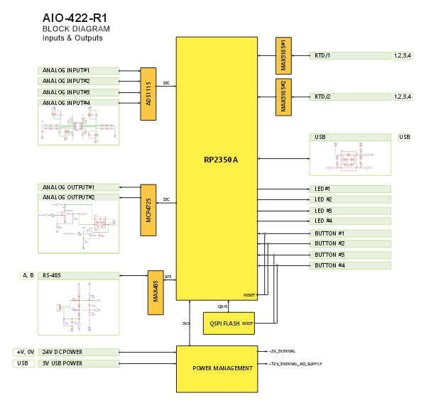
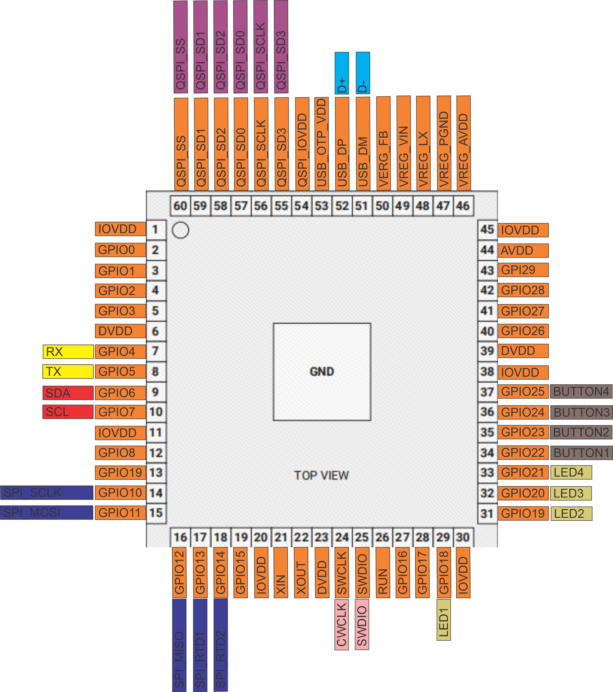
System Architecture & Pinout
Safety and Installation Notes
- SELV circuits: the power input and signal terminals are SELV circuits; install only in an appropriate control cabinet
- Qualified personnel only: installation by trained technicians familiar with analog wiring and industrial control safety
- Protect all module wiring terminals against accidental contact using the required front plate/door
- Do not expose the module to outdoor conditions; the enclosure is IP20 (inside cabinet only)
- Use the recommended cable types (twisted/shielded) to reduce noise and improve analog/RTD accuracy
- Keep analog/RTD cables separated from power and high-current wiring to avoid interference
Compliance & Certifications
The HomeMaster AIO-422-R1 is CE marked and designed to comply with applicable European Union directives. The manufacturer maintains technical documentation and a signed EU Declaration of Conformity (DoC).
EU Directives
EMC 2014/30/EU · LVD 2014/35/EU · RoHS 2011/65/EU
Harmonised Standards
| Area | Standards |
|---|---|
| EMC | EN 61000-6-1 · EN 61000-6-3 |
| Electrical Safety | EN 62368-1 |
| RoHS | EN IEC 63000 |
Safety Notice
The power input and signal terminals are SELV circuits. Relay/contact output circuits are not part of this module.
Related products
These other products might interest you