What Still Works When Home Assistant Is Down
Most smart homes have exactly one place where decisions are made, so when that place goes away the house goes with it. A wired system does not have to be built that way. Automation logic can sit on the module, on the controller or on the server — and which one you choose is a question about how critical the reaction is, not about which product you bought.

The short version. In a HomeMaster panel there are three places a rule can live. Every module is autonomous and does the job it was designed for on its own: a switch operates its relay, a leak closes its valve, a threshold sheds its load, a zone latches its sounder. The controller adds the extended logic — anything that spans several modules or needs values from more than one place. The server adds visualisation, history, remote access and everything that depends on the outside world. When Home Assistant goes down, the first two layers keep running; only the third stops. Where each rule belongs is decided by one question: how badly does the house need this reaction to happen right now?
1. The Three Places Automation Logic Can Live
Almost every argument about smart home reliability is really an argument about one question: when you press the switch, what decides?
In a cloud-first system there is only one honest answer — a server in somebody else's building. The switch tells a vendor's service, the service tells the lamp, and the light in the room you are standing in depends on your internet connection, on that data centre, and on the vendor's continued interest in the product. Everything downstream of that single point of decision fails together.
A wired system built on RS-485 has three levels to choose from instead, and they are not alternatives to one another — they stack. In a HomeMaster panel they map onto the layers set out on the platform overview: field devices, RS-485 modules, a controller and a home automation server.
The module. The input and the output are on the same device, and the rule connecting them is stored in that device's own flash and executed by its own processor. This is where the reactions live that have to happen whatever else is going on.
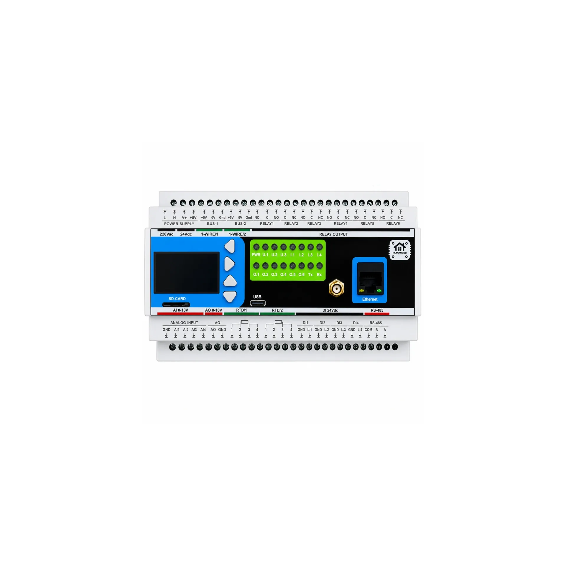
The controller. A MiniPLC or MicroPLC running ESPHome is the Modbus master on the bus, and it runs the extended logic: rules that combine values from several modules, sequences, comparisons, anything one module cannot see by itself. It is a device in the panel, not a service somewhere — it does not need the server and it does not need the internet.
The server. Home Assistant is where the house becomes visible and controllable: dashboards, history, notifications, remote access, voice, integrations with anything outside the building.
The point worth making early, because it is usually misunderstood: this is not an argument about protocols. Zigbee, Z-Wave, Thread and Wi-Fi can each be deployed at any of these levels. The question is never the radio. The question is which box is making the decision — and that choice should follow how critical the decision is.
2. What Actually Breaks, and What It Takes With It
"What if the server goes down" sounds like a hypothetical. In practice it is a small set of very ordinary events, and the useful thing about a layered system is that each of them only reaches so far.
The server updates. By far the most common one. Nothing is broken; you clicked update, and for the next ten or fifteen minutes there are no dashboards and no server-side automations. The modules and the controller do not notice.
The server fails. Storage wears out, a host does not come back cleanly after a reboot, a container refuses to start after a configuration change. Recovery takes as long as it takes you to sit down at a keyboard — and the house keeps operating at the two lower levels while you do.
The network drops. A router reboot, a switch losing power, an access point falling off. The server is healthy and simply cannot be reached. The RS-485 bus in the panel is not affected by any of it.
A vendor's service goes away. Not under your control and not fixable by you — which is precisely why nothing in this architecture is allowed to depend on one.
The power goes off. This one deserves its own treatment, because it is the only failure that no amount of local logic addresses. Section 7.
The reframing worth holding onto: the first four are all cases where the electricity is fine and the equipment is fine, and in a single-decision-point system the house stops responding anyway. That is a design decision, not an act of God.
3. What "Logic on the Module" Actually Means
The phrase gets used loosely, so it is worth being specific about the mechanism.
The configuration lives in the module's own flash. Each module stores its settings in an internal LittleFS filesystem, protected by a version stamp and a checksum, and reads them back on power-up. There is no configuration held on the controller that has to be pushed down, and no first-boot handshake that has to succeed before the module knows what its inputs are for.
The module reads its own inputs. Press timing — short press, long press, double press, press-and-hold — is measured by the module's processor with its own debounce and long-press thresholds. It does not depend on how fast the master happens to be polling, because the master is not involved in the measurement.
The module drives its own outputs. The link from an input to an output is evaluated in the module's own loop and written straight to the relay. So this chain:
sensor → bus → server → automation → bus → relay
is replaced, for the rules that belong on the module, by this one:
input → module logic → relay
Configuration is done over USB-C in the browser, in the module's own web interface, and stored on the module. It survives a power cycle and it does not depend on the controller being present.
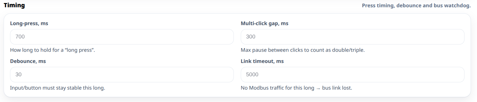
One detail worth stating plainly: the bus watchdog is an indicator, not a fail-safe. The Link timeout setting under Timing in the DIO-430-R1 web configuration does exactly what its help text says — "No Modbus traffic for this long → bus link lost". When the timeout expires the module changes its link indication and sets a status bit the master can read when it returns. It does not move any relay. Outputs stay where they were and local rules carry on running, which is the behaviour you want in a house: a relay that was on when the network died stays on, and the switch beside it still turns it off.
4. What Each Module Does On Its Own
Every module in the range is autonomous: it performs the job it was designed for without a controller on the bus. What follows is what that job is in each case, and where it is configured. All of it is set over USB-C in the module's own web interface and stored on the device.
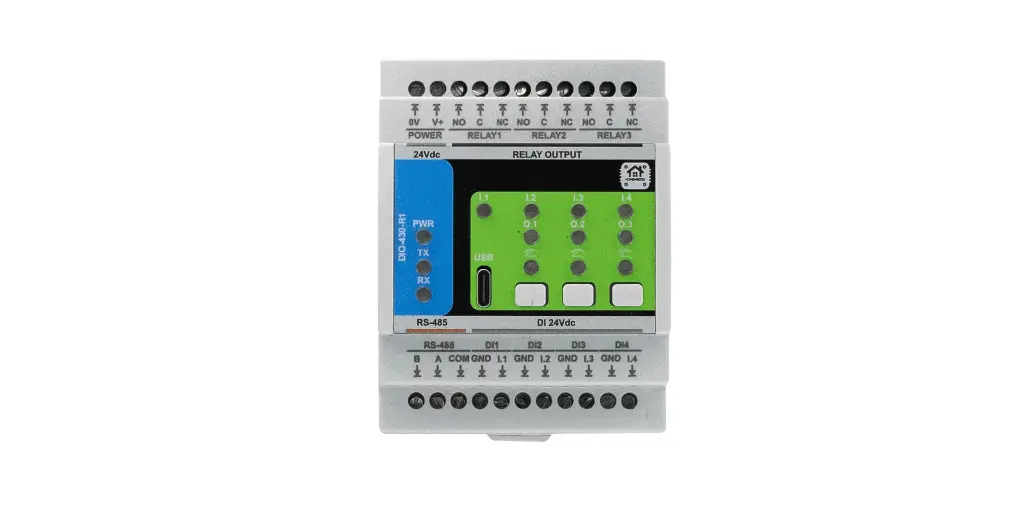
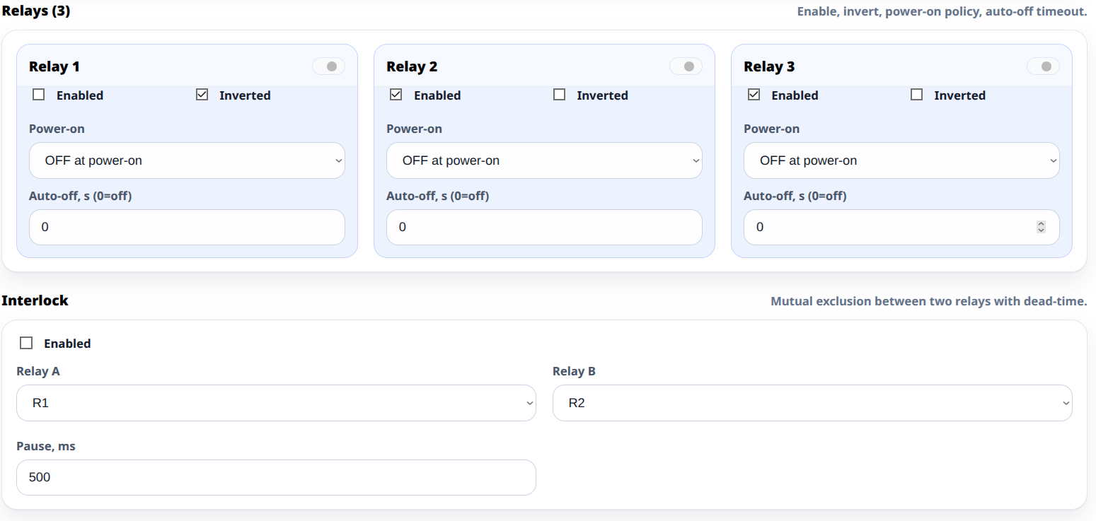
DIO-430-R1 — switches and relays. Digital inputs are tied to relays with an action per press type, so a wall switch operates its circuit directly. Each relay has a power-on policy — off, on, or restore the previous state — and an optional auto-off timer that switches it back off after a set number of seconds. There is also an interlock: two relays declared as a mutually exclusive pair with a dead-time pause between them, which is what you want for anything that must never be driven in both directions at once, such as a roller shutter or a valve actuator.
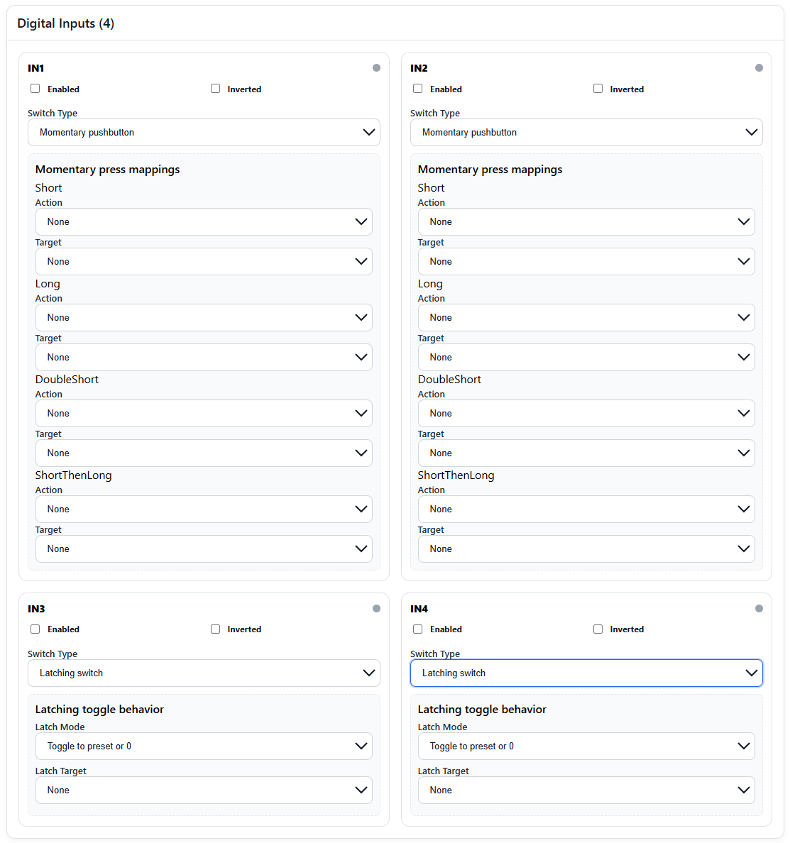
DIM-420-R1 — dimming. Each input is mapped to a dimmer channel, with separate actions for short, long, double and press-then-long, or a latching mode for a conventional switch. The switch on the wall dims its channel and a long press ramps it, with nothing else involved. Channels have their own power-on policy, and where that policy is "on" the channel comes up at its configured preset rather than at full output.
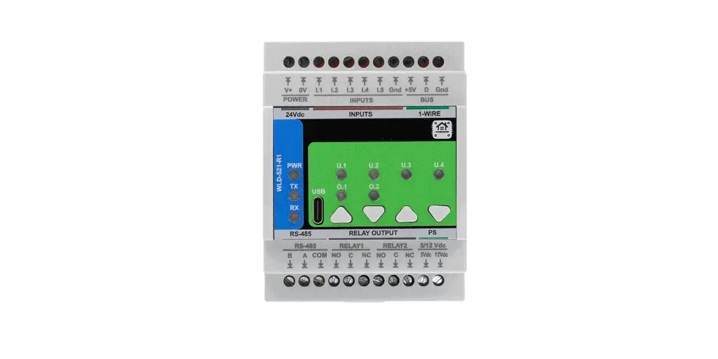
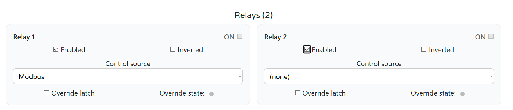
WLD-521-R1 — leaks and water. This is the clearest example of a job that must never wait for anything: a wet sensor closes the valve, on the module, immediately. Each relay has a control source so you can decide who owns it — the module's own leak logic, or the bus — and for leak protection the answer is the module. Pulse metering and 1-Wire temperature run alongside it and are read by the master when there is one.
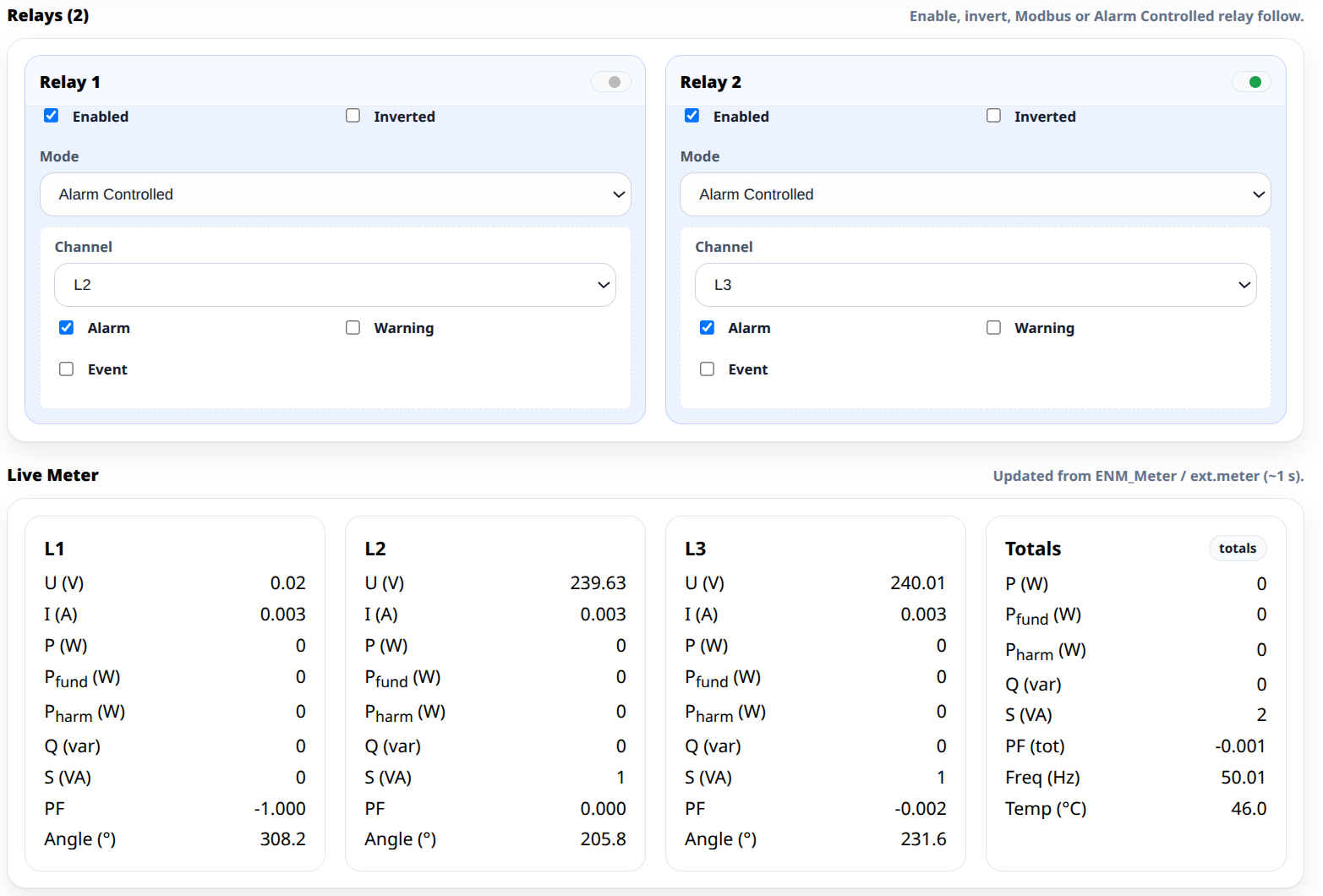
ENM-223-R1 — energy and thresholds. A relay can be set to alarm controlled, bound to a phase and to the alarm, warning or event condition of your choice. The threshold engine runs on the module, so a load-shedding rule — over this current on this phase, drop that contactor — fires on its own. When a relay is in alarm mode the bus does not write to it at all.
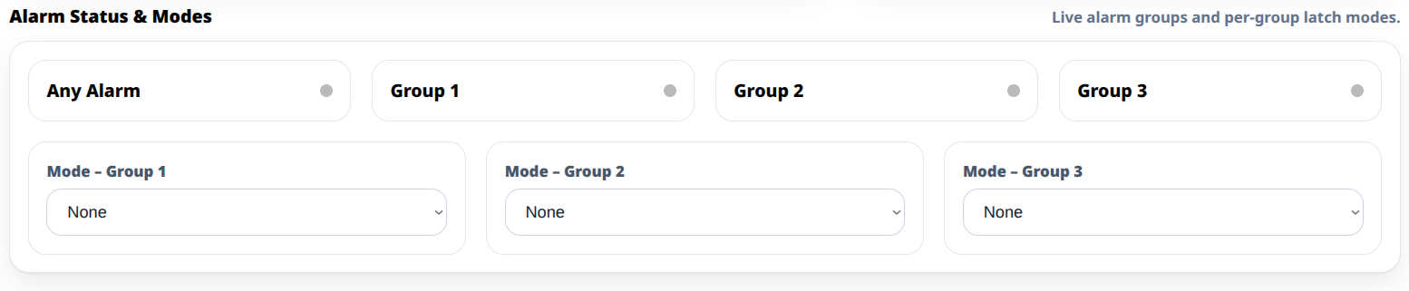
ALM-173-R1 — zones. Inputs are assigned to alarm groups, and each group has its own mode: follow the condition, or latch until acknowledged. A triggered zone holds its group active and holds the relay driving the sounder, and keeps holding it until somebody acknowledges — not until a server notices. Entry and exit delays and the sounder cut-off timer are on the module as well.
STR-3221-R1 — stair lighting. It runs from its own presence inputs and drives its own LED channels. The controller is what turns that into something more elaborate — brightness curves tied to time of day, coordination with the rest of the lighting — but the basic job, somebody on the stairs and the stairs lit, belongs to the module.
AIO-422-R1 — analog. Four 0–10 V inputs and two PT100/PT1000 RTD channels feed two 0–10 V outputs, and those outputs have a configurable power-on state — which is what stops a valve actuator from being driven to full travel the moment the panel is energised. How to wire the front end of all that is a subject of its own, covered in reading 4–20 mA and PT100 sensors without guesswork.
5. What the Controller Keeps Doing
The layer that usually gets forgotten in this discussion is the middle one, and it is the reason a HomeMaster panel degrades so gently.
A module can only decide using what is wired to it. The moment a rule needs two modules — a temperature from one and a pump on another, a leak in the basement and a light upstairs, a sequence that walks across several outputs — it needs something that can see both. That is the controller's job, and the controller is a device on the DIN rail in the same panel, running ESPHome, acting as Modbus master on the RS-485 bus.
Which means the extended logic is not server logic. It keeps running when Home Assistant is down, when the router is rebooting, and when the internet has been out all day. Typical examples:
- ΔT control. Two temperatures from different modules, compared, and a pump relay driven from the result.
- Cross-module reactions. A leak detected on one module also shutting off circuits on another.
- Sequences and staging. Anything that has to happen in order across several outputs.
- Local scenes. One input setting several modules at once.
So the honest picture of a Home Assistant outage is not "everything falls back to switches". It is: the modules keep doing their jobs, the controller keeps running the logic that spans them, and what you lose is the layer above both.
6. What Stops Anyway
The previous two sections are only credible next to this one. Here is what genuinely goes away with the server.
Status and history. Relays change state and nothing records it, because the thing that records it is the thing that is down. Your energy graphs have a gap exactly the shape of the outage.
Notifications. The zone latched, the valve closed — and nobody was told. The alarm state is waiting in the module for the server to come back and read it, which is useful afterwards and no use at the time.
Remote access. Nothing responds from outside the building, because the thing that answers from outside is the server.
Anything that depends on the outside world. Weather compensation, calendars, energy tariffs, third-party integrations, anything driven by an API. The module cannot know it and the controller cannot fetch it.
The interface itself. Dashboards, voice, presence from phones, and the automations you wrote in the server rather than in the panel.
The right sentence to hold onto: the two lower layers hold the house together, and the server is what makes it observable and connected. During an outage the house is quieter and less informed than usual. It is not dead, and nothing is waiting on a reboot to behave.
7. Power: The Failure Nobody Survives
This section is short and deliberately unflattering.
Nothing in the panel does anything without its 24 V supply. "Works when the server is down" and "works when the electricity is off" are two completely different claims, and blurring them is the fastest way to lose somebody's trust at exactly the wrong moment.
Three practical consequences:
- If continuity through a power cut matters, that means a UPS on the automation supply, sized for the control side and separate from the load side. Keeping a relay module and a controller alive is a very different proposition from keeping a pump running.
- The field devices need their own power. A valve actuator, a sounder and a shutter motor are not powered by the module that commands them.
- After power is restored, outputs come up according to their power-on policy, not according to what they were doing before the cut. That policy is a per-output setting — off, on, or restore the previous state — and it is worth deciding deliberately for anything that matters rather than leaving it at the default.
8. How to Decide Where a Rule Belongs
All of the above is only useful if you place rules deliberately. The criterion is criticality, and it sorts almost everything on the first try.
Put it on the module when the reaction has to happen whatever else is going on, within a second, and its absence would be immediately obvious or immediately expensive:
- Lights on a switch in the same room
- Closing a valve when a leak is detected
- Shedding a load when a threshold is crossed
- Latching an alarm zone and driving the sounder
- Interlocking two directions of an actuator so they can never be driven together
Put it on the controller when the rule needs more than one module to decide, but still has to work with no server and no internet:
- Comparisons between values from different modules, ΔT being the classic case
- Sequences and staging across several outputs
- Cross-module reactions and panel-wide scenes
Leave it on the server when the rule needs information from outside the building, or exists for a human to look at:
- Weather compensation, tariffs, calendars, presence from phones
- Dashboards, history and notifications
- Voice and remote control
Designing this way has one wiring consequence worth planning for early: a switch and the load it controls should land on the same module. Put them on different modules and the rule moves up a level by construction — it still works, but it now needs the controller. When you lay out the panel, group by room and function rather than by cable route. The System Builder is useful for working out how many modules that grouping implies and how wide the panel ends up. How the layers fit together is set out on the platform overview.
9. Test Your Own Fallback Before You Need It
Every panel is configured differently, so the only trustworthy answer is the one you get from your own. Run this in daylight, with nobody depending on the outcome, and write down what happens at each step.
| Step | What to do | What should still work |
|---|---|---|
| 1 | Shut the Home Assistant server down, leave the panel powered | Everything on the modules and everything on the controller |
| 2 | Unplug the controller's network connection | The same again — the bus is unaffected by the network |
| 3 | Power the controller down completely | Only the rules stored on the modules |
| 4 | At each step: press every wall switch you care about | The light, the shutter, the dimmer channel |
| 5 | At each step: wet a leak sensor with a damp cloth | The valve closing |
| 6 | At each step: open an alarm zone | The group latching and the sounder relay pulling in |
| 7 | Finally, cut the 24 V supply and restore it | Nothing during; afterwards, outputs at their power-on state |
Step 3 is the interesting one, because it is the step that tells you which of your rules were quietly written at the controller level. Anything that stops there is extended logic — which may be exactly right, as long as you know it.
Re-run the test after changes: after rewiring, after reconfiguring a module, and after a firmware update. Better to find a surprise during a test than during an outage.
Doing this once, before the house is occupied, is worth more than any specification sheet. It leaves you with a written list of what your particular installation does when things go wrong.
10. What This Is Not
Not a safety system. There is no functional safety rating, no certification for life-safety use and no redundancy. This is convenience and property-protection automation that degrades gracefully, not a safety instrumented function. The ALM-173-R1 in particular monitors dry contacts and drives a sounder relay; it is not a certified alarm system and should not be presented as one.
Not power backup. See section 7. Nothing here runs without 24 V.
Not a replacement for the server. The list in section 6 does not shrink. The lower layers hold the house together; the server is what makes it observable, connected and pleasant to use.
Not automatic. A rule runs at the module level because somebody put it there. The architecture makes it possible; the configuration makes it real, and the test in section 9 is how you find out which you have.
11. The Takeaway
The interesting question about a smart home is not how clever it is when everything is running. It is what it does on the ordinary evening when the server is halfway through an update and somebody walks in and reaches for the switch.
If the answer is "the light comes on, and the heating is still deciding for itself", you have built something people can live with. Getting there does not take a different protocol or a more expensive controller. It takes deciding, rule by rule, which of the three levels the decision belongs at — and wiring the panel so that the critical ones can sit at the lowest.
Then test it, write down what you found, and test it again the next time you change something.
If you are planning the wiring that makes this possible, the companion pieces are connecting dozens of wired sensors without a wall of boards and reading 4–20 mA and PT100 sensors without guesswork. For the whole picture from the start, see Building a Wired ESPHome Smart Home.