Reading 4–20 mA and PT100 Sensors in ESPHome Without Guesswork
A pressure transmitter gives you a current, not a voltage. A PT100 gives you a resistance, and your cable is part of it. ESPHome makes the software easy — but the electrical interface has to be right first. Here is what actually happens between the sensor and Home Assistant, including the resistor value most guides get wrong.

The short version. Industrial sensors rarely produce a signal you can wire straight to a GPIO. A 4–20 mA transmitter needs a sense resistor to become a voltage, and the value of that resistor is not a detail — 500 Ω puts the top of the range exactly on the ceiling of a 0–10 V input, with no headroom at all. A PT100 needs three or four wires as soon as the cable is long, because the cable is part of the measurement. This article works through both, plus what it costs to buy the interfaces finished instead of building them from breakout boards.
1. Why the ESP32 ADC Can Give You the Wrong Answer
The ESP32 has an integrated ADC, so reading an analog sensor looks easy at first: connect the signal, configure an ADC component in ESPHome, read the value. The problem is that this ADC is not a precision measurement front end. It is nonlinear, it is sensitive to noise, and its reading depends on the electrical environment and the supply.
For a potentiometer or a light sensor, none of that matters. For a pressure transmitter it matters a great deal — because the transmitter is very likely the most predictable part of the chain, and feeding its signal into a noisy nonlinear ADC makes the measuring device the weakest link.
This is why so many apparently simple ESP32 sensor projects end up accumulating filtering, calibration, an external ADC board and extra signal conditioning. The usual progression is familiar: it worked on the bench, and then the value started wandering once it went into the cabinet.
The electrical interface deserves as much attention as the YAML.
2. The 4–20 mA Current Loop
The 4–20 mA current loop is standard in industry because the information is carried by current rather than voltage. A typical two-wire transmitter sits in a loop with the supply and the receiving device, and the whole loop carries the same current.
Three things follow from that, and all three are the reason the standard has outlived everything around it:
- 4 mA is the bottom of the range and 20 mA is the top. The zero of the measurement is 4 mA, not 0 mA.
- A broken loop is distinguishable from a real zero, precisely because a healthy sensor never sends 0 mA.
- Voltage drop along the cable does not corrupt the reading, because current is the same everywhere in a series loop.
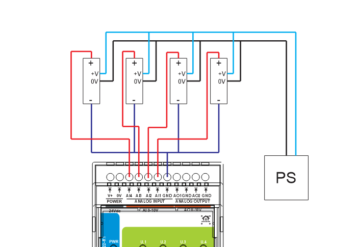
What does not follow is that you can plug it into a voltage input. A 4–20 mA transmitter connected to a 0–10 V input reads nothing useful. The current has to be turned into a voltage first, and that is done with a resistor in the loop — a sense resistor, sometimes called a shunt.
The principle is one line:
4–20 mA → sense resistor → a voltage the analog input can measure
3. Sizing the Sense Resistor: Why 470 Ω and Not 500
This is the part that decides whether the installation works at the top of its range, and it is worth two minutes of arithmetic.
The sensor pushes 4–20 mA through your resistor, so the voltage the module sees is simply Ohm's law:
So the resistor value sets the span, and the only hard constraint is that the top of the range has to stay inside the input. Our first build used 510 Ω, and that is exactly where the arithmetic goes wrong:
| Resistor | At 4 mA | At 20 mA | Verdict |
|---|---|---|---|
| 510 Ω | 2.04 V | 10.20 V | Overshoots the 0–10 V input — the top of the scale is unreadable |
| 500 Ω | 2.00 V | 10.00 V | Lands exactly on the ceiling. No headroom at all |
| 470 Ω | 1.88 V | 9.40 V | Recommended. Standard value, 6 % headroom at full scale |
| 499 Ω (0.1 %) | 2.00 V | 9.98 V | Tidy round numbers, almost no headroom — the precision option |
With 510 Ω on a 0–30 m/s wind sensor, everything above roughly 29.4 m/s lands past the top of the input range. On a domestic mast you may never see it. On a site where the top of the scale is the reading that matters, you lose exactly the event you installed the sensor for.
Two more things about that resistor.
Its tolerance is your accuracy. The value scales every reading one for one — a 5 % resistor is a 5 % error before you have measured anything, and it drifts with temperature as well. Use 1 % metal film, or 0.1 % where the numbers matter. Better still, measure the part you actually fitted and put that value into the configuration.
Its power rating is a non-issue. 20 mA through 470 Ω dissipates under 0.2 mW. Any ordinary part will do.
For a full worked example with real sensors, wiring and the ESPHome maths, see reading industrial wind sensors with the AIO-422-R1.
4. What the AIO-422-R1 Actually Accepts
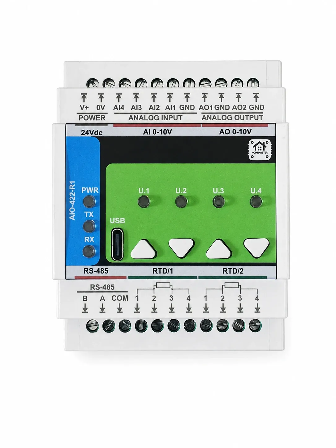
The first thing to understand about the AIO-422-R1 is what it does not do. It accepts 0–10 V analog inputs. It does not accept a 4–20 mA signal directly. There is no current-input mode to enable; the conversion happens in the resistor, outside the module, before the input sees anything.
The module provides four 0–10 V analog inputs on a 16-bit ADS1115, with an input resistance above 100 kΩ. That high input resistance is what makes the arrangement work: the sense resistor develops the voltage, and the input measures it without diverting a meaningful share of the loop current away from the resistor. A low-impedance input in parallel would take part of the current and drag the reading down.
It occupies four DIN modules and runs from the panel's 24 V DC supply, so nothing extra has to be found for it.
5. PT100, PT1000 and Why Three Wires Exist
A PT100 is a resistance temperature detector. The measurement is a resistance, which creates an immediate problem: the cable between the probe and the measuring circuit has resistance too, and the circuit cannot tell the two apart.
At its reference temperature a PT100 is around 100 Ω. A few tenths of an ohm contributed by the wiring is therefore a visible temperature error. That is the whole reason three- and four-wire connections exist.
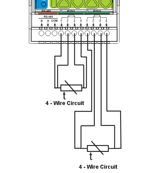
Two-wire measures sensor resistance plus cable resistance, and cannot separate them. Fine on a short run, wrong on a long one. Three-wire uses the wiring arrangement to compensate for the resistance of the connecting conductors — the usual compromise between accuracy and cabling effort. Four-wire separates the current path from the voltage measurement path, which removes the conductor resistance from the result. On a long run it is the cleanest of the three.
The practical rule: the longer the cable, the less attractive a two-wire PT100 becomes. That is exactly the case when the probe sits at a boiler, a buffer tank, a pipe, a heat exchanger or outdoors, and the controller is in a cabinet somewhere else.
PT1000 is the same principle with ten times the resistance. Around 1000 Ω at the reference temperature instead of 100, which means the cable contributes a ten times smaller share of the total. On a long run PT1000 forgives more. It does not make the measurement accurate by itself — routing, terminations, electronics and the probe's own tolerance all still apply.
6. Building the RTD Input Yourself
You can absolutely build an RTD input for an ESP32. The architecture is short: ESP32 → MAX31865 → PT100 or PT1000. The MAX31865 exists specifically for this job and it does it well.
The electronics are the easy part. The integration is where the time goes:
- choosing the reference resistor to match the probe;
- configuring the board for PT100 or PT1000;
- deciding between two-, three- and four-wire connection and wiring it accordingly;
- connecting SPI correctly;
- choosing ESP32 pins that actually work for it;
- configuring the software component;
- calibrating the result.
Pin choice is not a formality. SPI is not one abstract interface — the ESP32 variant and the specific GPIOs matter, and a wiring that works on one board can misbehave on another. A MAX31865 breakout wired to an arbitrary set of pins is a common way to turn an afternoon into a debugging session.
And Arduino code is not ESPHome configuration. The same chip working under an Arduino library does not mean the implementation transfers: ESPHome has its own component model. The hardware is identical; the software integration is not.
None of this is an argument against doing it yourself. It is an accurate description of what the job contains. A finished module differs in one respect: the reference resistor, the jumper options and the field wiring are already reconciled with each other.
7. The RTD Inputs on the Module
The AIO-422-R1 has two RTD channels on the MAX31865, supporting PT100 and PT1000 in two-, three- and four-wire connection.
The configuration is selected per channel with jumpers J1–J8 on the field board, and the reference resistor follows the sensor type. The factory position is PT100 in two-wire mode.
That last sentence is worth reading twice before ordering probes. An RTD input is not simply a connector for a temperature sensor: the measuring circuit has to match the resistance range and the wiring of the actual probe. Fit a PT1000 while the interface is set for a PT100 and the hardware and the sensor disagree.
8. Analog Outputs: Measuring and Controlling from One Module
The AIO-422-R1 is not only an input module. It also has two 0–10 V analog outputs on a 12-bit DAC, with a recommended output current of up to 10 mA per channel and a configurable state at startup.
That combination is the point: read a process value and produce the control signal for it from the same device, on the same bus address. Typical 0–10 V consumers are mixing-valve actuators, speed references for variable-frequency drives, dimmable electronic ballasts and 0–10 V LED drivers.
A 0–10 V output is a control signal, not a power output. It does not drive a motor or a valve; it tells the external device what to do, and that device has its own supply.
Why the startup state is worth caring about. Consider a valve actuator on 0–10 V. If the output sits at an unintended value while the controller boots, the actuator starts moving before any control logic has run. Being able to define what the output does at power-up is a small feature that matters more in a real cabinet than another couple of bits of resolution.
9. Bringing It Into Home Assistant
The module talks Modbus RTU over RS-485, and a MiniPLC or MicroPLC acts as the master. The chain is:
sensors and actuators → AIO-422-R1 → RS-485 → MiniPLC or MicroPLC → ESPHome → Home Assistant
The module is a standard Modbus RTU slave: address 1–247, 9600 to 115200 baud, configured over USB-C in WebConfig. Being standard, it is equally reachable from a third-party PLC or a SCADA system — it is not tied to the controller it was bought with.
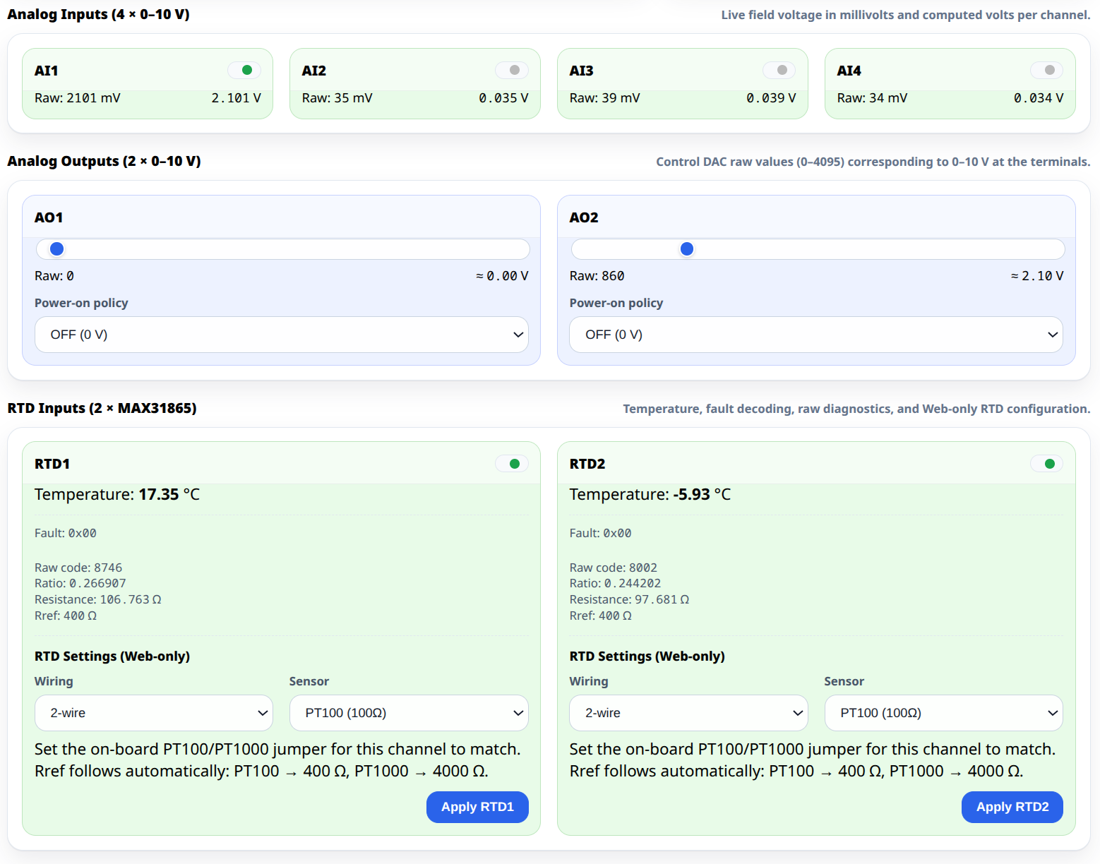
WebConfig earns its place before Home Assistant is involved at all. It shows live values from the analog inputs, the analog outputs and the RTD channels straight in the browser, which means the electrical installation can be verified on its own:
First verify the signal. Then verify Modbus. Then verify Home Assistant.
Three separate questions instead of one tangled one — which is the difference between finding a fault in ten minutes and losing an evening.
10. What It Costs Against a Pile of Breakout Boards
This is where the comparison gets uncomfortable, and therefore useful.
At the list price at the time of writing the AIO-422-R1 is €127.05 including VAT. A do-it-yourself equivalent — an ESP32, an ADS1115 breakout, a MAX31865 breakout, precision resistors, an enclosure and a power supply — costs a small fraction of that in parts. On components alone there is no contest, and pretending otherwise would be insulting.
So the honest question is not which is cheaper. It is what the difference buys:
- DIN-rail mounting in four modules, in the same cabinet as everything else;
- one RS-485 device instead of several network-connected boards;
- four 0–10 V inputs, two RTD channels and two 0–10 V outputs already reconciled with each other;
- jumper-selected RTD type and wiring mode with a matching reference resistor;
- field-side circuitry, terminals and cable entry designed for a panel rather than a bench;
- 24 V panel power instead of another adapter;
- one configuration tool for all of it.
When do-it-yourself still wins: one sensor, a short cable, a prototype. Build it.
When the module wins: several analog sensors plus RTDs plus analog control, in a cabinet, in an installation you or someone else will have to service in three years.
The value is not the price of an ADS1115 against the price of a module. It is the wiring, mechanical work, configuration and integration you do not have to invent.
11. Calibration: Resolution Is Not Accuracy
Sixteen bits sounds impressive. Sixteen-bit resolution is not sixteen-bit accuracy, and the difference is where most disappointment comes from.
For a 4–20 mA input the result depends on the sense resistor's value and its stability, on temperature, on cable length and construction, on shielding and how it is grounded, on how close the run passes to mains and switching equipment, on electrical noise, and on the accuracy class of the sensor itself.
A perfectly configured ADC cannot compensate for a badly installed cable, and a high-resolution ADC cannot turn a 1 % sensor into a precision instrument.
Treat an analog run as an analog run. Twisted pair per channel, shield bonded at the controller end only, routed away from power conductors, crossing them at right angles where it must. Share the ground: the loop's 0 V and the module's analog ground must be the same node, or the reading drifts with everything else in the cabinet.
The measurement chain is sensor → cable → field wiring → signal conditioning → ADC or DAC → firmware → Home Assistant, and every link contributes.
12. What the AIO-422-R1 Is Not
It does not accept 4–20 mA directly. The inputs are 0–10 V; a current loop needs an external sense resistor. This is the single most common misunderstanding about the module, which is why it appears twice in this article.
It has no digital inputs and no relays. It is an analog module, not a general-purpose I/O card. Dry contacts belong on a different module.
The RS-485 port is not galvanically isolated. There is transient protection, which is not the same thing. Where isolation between electrical domains is required, fit an external isolated RS-485 interface.
It is IP20 and specified for 0 °C to +40 °C. A closed control cabinet in a heated part of the building — not an outdoor enclosure, not an unheated garage.
It is not a metrological instrument. There is no stated accuracy class, so it should not be presented as certified measurement. What can be stated is the architecture: 16-bit ADS1115 inputs, MAX31865 RTD channels, a 12-bit output stage and the supported wiring configurations.
13. Choose the Module by the Signal, Not by the Sensor Name
One of the easiest mistakes in automation is classifying equipment by what it measures instead of by how it communicates. "Temperature sensor" describes a purpose, not an electrical interface — it can be 1-Wire, a PT100 or PT1000 RTD, 0–10 V or 4–20 mA, and those are four different things to wire. The same is true of pressure.
So the useful question is not which module supports your temperature sensor. It is what signal your sensor actually produces.
| Signal or function | Module |
|---|---|
| Dry contact | ALM-173-R1 |
| 0–10 V analog, PT100 / PT1000 RTD | AIO-422-R1 |
| Leak detection, pulse counting, 1-Wire temperature | WLD-521-R1 |
To work out how many of each a panel needs and how wide it comes out, use the System Builder.
14. The Takeaway
ESPHome makes industrial sensors far more accessible than they used to be, but it does not remove the electrical engineering underneath them. A 4–20 mA transmitter is a current-loop device. A PT100 is a resistance measurement, and the cable is part of it. A 0–10 V actuator wants an analog control voltage. Each of those needs the right signal conditioning before any software becomes relevant.
For a one-off experiment, breakout boards are cheaper and that is a legitimate answer. For a panel with several field devices that has to be wired, configured and troubleshot systematically, the advantage is not ADC resolution — it is having the interfaces, the wiring options, the mechanical format and the bus brought together in one device.
That is the difference between making a sensor work on a bench and building an installation that still reads true in three years.
If you are wiring a house from scratch, the companion piece is Building a Wired ESPHome Smart Home. If you have dozens of dry contacts rather than analog signals, see connecting dozens of wired sensors without a wall of boards.
Prices quoted are list prices including VAT at the time of writing, shown in euro for comparability. Check the product page for current pricing in your currency.