How to Connect Dozens of Wired Sensors to Home Assistant Without a Wall of Boards
The first few wired sensors are easy. At thirty the cabinet starts to matter, and at sixty the architecture matters more than the individual input. This is how the arithmetic actually works: how many modules, how much DIN width, how much sensor current — and what an input really costs when you stop counting only the GPIO.

The short version. Wiring one sensor into Home Assistant is easy; ESPHome does that well. Wiring sixty is a different problem, because every additional bank of inputs normally drags along another controller, another power supply and another device that can vanish from the network. Putting the inputs on an RS-485 Modbus RTU bus breaks that link: input modules become field nodes with Modbus addresses instead of network endpoints. This article works through the real numbers — modules, DIN width, sensor current budget and cost per input — including the part where a bare sixteen-input board is ten times cheaper per input than we are, and when that is the right answer.
1. Where the Problem Starts
The usual installation starts innocently. You connect several door contacts to an ESP32 and expose them to Home Assistant through ESPHome. Then you discover that the ESP32 does not have an unlimited number of useful GPIOs — some pins are already taken by flash, USB, Ethernet or UARTs, and others carry electrical restrictions. So you add another board.
The second board solves the input count and creates an architecture problem. Now there are two controllers, two network connections, two power connections, two firmware configurations, and two devices that can disappear from the network. And if the sensors are spread around the building, you still have to get their wiring back to those boards.
At that point most people look for a dedicated wired-alarm I/O board. That is better integrated, but it does not change the underlying scaling problem if every additional group of zones still requires another network-connected controller.
There is a third option: put the input expansion on a field bus instead of putting every bank of inputs on the network.
2. Three Ways to Get Many Inputs
There are three fundamentally different architectures, and the difference is not the input itself.
| Architecture | What happens when you need more inputs | Main limitation |
|---|---|---|
| Microcontroller GPIO board | Add another controller board | Limited GPIO, and another network device each time |
| Dedicated wired-alarm board | Add another alarm I/O board | Usually a fixed number of zones per board |
| RS-485 I/O bus | Add another bus module | Bus design, addressing and the sensor power budget |
The number that matters is not cost per input. It is input plus wiring plus power plus enclosure plus network connection plus controller plus failure point. A twenty-euro sixteen-input board is genuinely attractive if you need sixteen inputs and everything else is already solved. A large installation asks a different question: how many complete devices do I have to install to get sixty inputs?
3. What the Bus Actually Changes
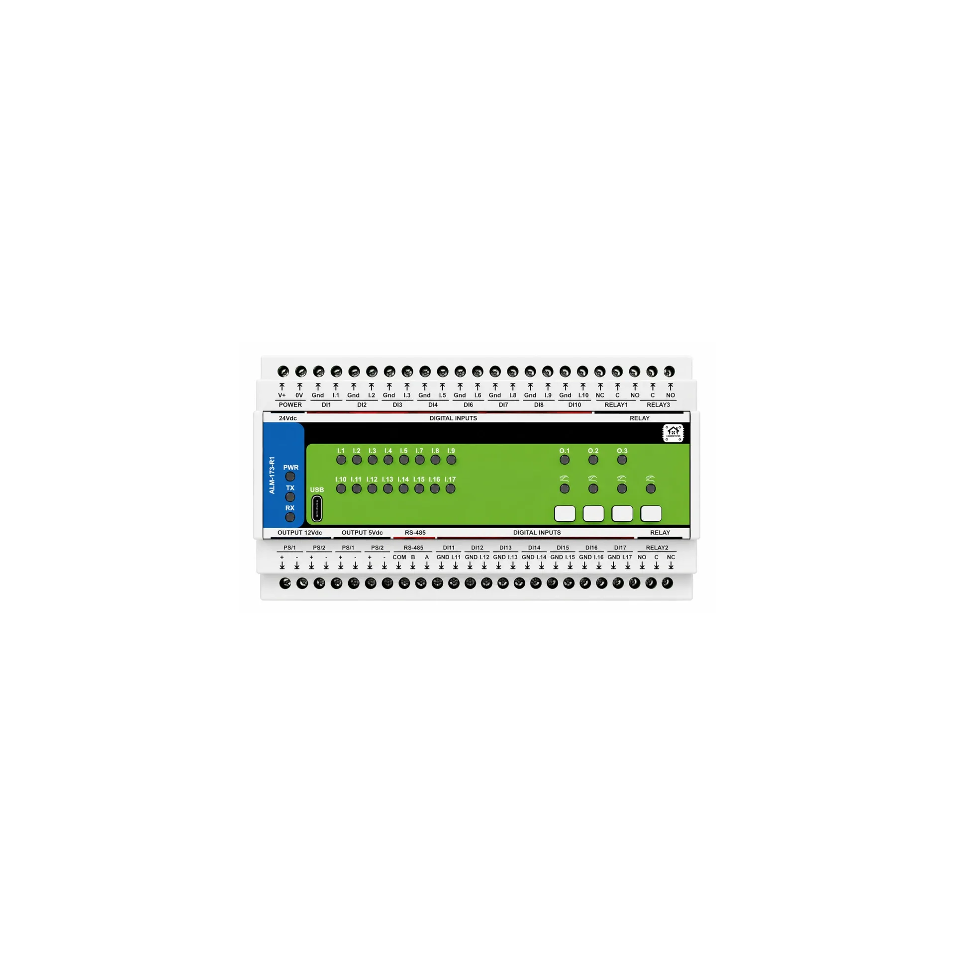
The HomeMaster architecture uses RS-485 with Modbus RTU. The controller is the Modbus master; the ALM-173-R1 modules are slaves on the bus. The input modules need no IP address, no Wi-Fi connection, and they do not appear as separate network devices. The controller talks to them over one RS-485 pair and publishes their data to Home Assistant through the native ESPHome API. The module is a standard Modbus RTU slave, so it also works with a third-party PLC or a SCADA system.
The ALM-173-R1 supports Modbus addresses 1–247 with address 3 as the default, and baud rates from 9600 to 115200 with 19200 8N1 as the default.
One network device instead of ten. Suppose a house eventually needs ten groups of inputs. With independent controllers those groups become ten network endpoints. On a bus they remain field I/O nodes behind one controller: the controller has the IP address, the modules have Modbus addresses. The network topology becomes independent of the number of sensor inputs, and adding another input module no longer means adding another Wi-Fi client or Ethernet port.
One bus instead of a collection of independent connections. RS-485 is designed for multi-drop serial communication. Run the communication pair from node to node rather than creating star branches, and fit 120 Ω termination at the two physical ends of the bus only — not at every node.
Run COM to every node on the bus, not just to the ends. A two-wire A/B installation without a common reference conductor works until it doesn't, and the failure is intermittent and unpleasant to diagnose.
One limitation that should not be hidden: the RS-485 interface on the ALM-173-R1 is not galvanically isolated. The sensor inputs are opto-isolated at 5300 VRMS, but the transceiver shares the device's logic ground. The board has TVS surge protection, resettable PTC fuses, common-mode filtering and fail-safe biasing — that is transient protection, not galvanic isolation. Where the bus crosses into a separate electrical installation with its own earthing reference, fit an external isolated RS-485 interface at that boundary.
4. Who Powers the Sensors?
This is the least obvious problem in a large wired installation, and it is usually what breaks a plan that counted only terminals.
A door contact is easy — it is just a contact. A PIR detector is not: it needs a signal connection and a power connection. Twenty powered detectors means distributing power to twenty places, which normally means another power supply and another distribution block in the cabinet.
The ALM-173-R1 carries isolated sensor power for exactly this. On the isolated ground domain it provides +12 V shared at 150 mA across the PS/1 and PS/2 branches and +5 V at 200 mA, both protected, on a common isolated sensor ground. These are not four independent islands — the 12 V budget is shared.
So the number that limits a module is not seventeen terminals. It is the sensor current budget.
| Sensor type | Typical current | How many fit in 150 mA |
|---|---|---|
| PIR motion detector | 10–20 mA | 6–10 |
| Curtain PIR | 10–15 mA | 8–12 |
| Dual-technology detector (PIR + microwave) | 20–30 mA | 4–6 |
| Glass-break detector | 15–25 mA | 6–8 |
| 12 V smoke detector with relay output | 20–50 mA | 3–6 |
| Gas or CO detector with relay output | 30–60 mA | 2–4 |
| Infrared beam sensor or photoelectric barrier | 20–40 mA | 3–6 |
| Inductive or capacitive proximity sensor (NPN) | 5–15 mA | 8–15 |
The arithmetic is worth doing explicitly. Eight PIRs at 15 mA each draw 120 mA and fit inside the 150 mA budget. Eight smoke detectors at 40 mA each draw 320 mA and do not — those need an external supply. Always calculate from the detector's own datasheet rather than from the table.
When planning a large installation, count inputs and sensor current as two separate budgets.
5. How Many Modules Does a Real House Need?
Each ALM-173-R1 provides 17 digital inputs, so the scaling is simple arithmetic.
| Zones required | ALM modules | Available inputs | Spare inputs | DIN width |
|---|---|---|---|---|
| 18 | 2 | 34 | 16 | 18 DIN |
| 30 | 2 | 34 | 4 | 18 DIN |
| 50 | 3 | 51 | 1 | 27 DIN |
| 60 | 4 | 68 | 8 | 36 DIN |
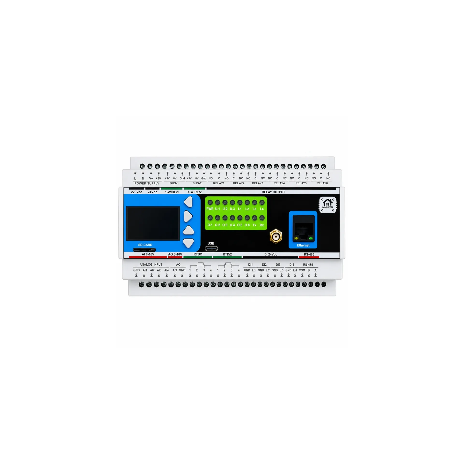
Each ALM-173-R1 is 9 DIN modules wide. Then add the controller: the MicroPLC occupies 2 DIN modules and the MiniPLC occupies 9. So sixty zones on four ALM modules plus a MicroPLC comes to 38 DIN modules of active equipment — before the power supply, breakers, terminal blocks, cable duct and spare space that any real cabinet also needs.
The spare inputs are not waste. They are the doors, windows, tamper circuits and equipment alarms you will add in the next three years.
What does an input actually cost? This is where the comparison becomes less comfortable, and therefore more useful.
At the list price at the time of writing, the ALM-173-R1 is €205.70 including VAT. Across seventeen inputs that is about €12.10 per input. A bare sixteen-input board of the kind sold for around €20 works out at roughly €1.25 per input. A ready-made wired-alarm interface board of around €200 covering twelve zones works out at roughly €16.70 per input.
So on price per input the module is about ten times a bare board, and slightly below a ready-made alarm interface.
If all you need is sixteen simple contacts, and you are comfortable supplying, enclosing, wiring and integrating the board yourself, the cheap board can be the better economic choice. That is a real answer, not a rhetorical one.
The reason to use a DIN-rail I/O module is not that the individual input is cheap. It is that the input arrives as part of a field-installation subsystem. In one DIN-rail module the ALM-173-R1 combines seventeen opto-isolated inputs, 5300 VRMS input isolation, isolated 12 V and 5 V sensor supplies, RS-485 Modbus RTU, three relay outputs, local alarm grouping with latching and acknowledgement, optional local arming, persistent configuration and a cabinet-ready enclosure.
The honest framing is not cheap input versus expensive input. It is bare PCB versus complete field I/O node — and which of those you need depends entirely on how big the installation is.
6. Reusing Old Alarm Wiring
This is one of the most useful applications for a system like this, and one of the most common questions.
A house may already have dozens of cables running from doors, windows and motion detectors back to where an old alarm panel used to be. The panel gets removed. The cables stay in the walls. Replacing those cables is usually far more expensive than replacing the electronics.
If the existing wiring is in good condition and electrically suitable, it can become the field wiring of the Home Assistant installation. Typical existing circuits include door and window contacts, garage door contacts, motion detectors, tamper switches, glass-break detectors, gate contacts, shutter end-position contacts and siren wiring.
Two kinds of circuit, two treatments. Dry-contact zones — reed contacts, tamper switches, other passive contacts — need no power; the two wires simply represent the state of the contact, and they land straight on the inputs. Powered detectors need both power and a signal circuit, and those are the ones where the module's own isolated 12 V supply removes a whole distribution problem from the cabinet.
The ALM-173-R1 is designed for dry-contact and SELV low-voltage signals, so every existing circuit has to be checked individually before it is connected. Old does not automatically mean compatible.
What about the old panel's end-of-line resistors? This is a real limitation and worth stating plainly. The ALM-173-R1 does not implement end-of-line resistor line supervision, so it does not reproduce the supervision behaviour of a traditional alarm panel. A conventional panel uses an EOL resistor to distinguish normal, alarm and certain wiring faults from each other. This module does not measure the loop that way.
There is a practical partial answer: wire security zones normally closed and use the input inversion function. A cut or disconnected wire then reads as the same state as an opened zone, so a damaged loop is visible instead of failing silently. That is useful, and it is not the same thing as EOL supervision. If graded line supervision is a requirement, use a system designed for it.
7. What Continues Working When Home Assistant Is Down
This is where a bus input module stops being a remote GPIO expander.
The ALM-173-R1 has its own local alarm logic. Inputs are assigned to alarm groups; groups run in modes including active-while and latched-until-acknowledge; the module drives its own relay outputs from those groups; and the whole configuration is stored in on-device flash. Zone types include Instant, Delayed and 24h/Tamper, and optional local arming adds entry and exit delays.
So the basic reaction does not have to travel sensor → network → Home Assistant → automation → network → relay. It can stay as sensor → input → local alarm logic → relay, executed on the module. If Home Assistant is updating, the controller is off or the network is down, that reaction still happens.
What does not continue is everything that belongs to Home Assistant itself: the interface, notifications, history, and any Home/Away/Night logic implemented on the server. Nothing makes an offline application keep running. The point is narrower and more useful than that — the local reaction does not depend on it.
8. What This System Is Not
It is not a certified intruder-alarm system. The ALM-173-R1 is an automation and monitoring module with alarm-style logic. It is not certified to any security grade and should not be specified where an insurer, a regulation or a project specification requires a graded alarm system.
It does not provide end-of-line supervision. See the previous section for what can and cannot be done about that.
The RS-485 port is not galvanically isolated. The inputs are, at 5300 VRMS. The bus interface is not. Where isolation between electrical domains is required, fit an external isolated RS-485 interface.
The relay outputs are not power relays. They are rated 3 A at 250 V AC resistive as a module-level system limit, which suits control duties — a siren, an indicator, a contactor coil. Heavier or inductive loads go through an external contactor or an appropriately rated power relay.
It lives in a cabinet, indoors. The module is IP20 and specified for 0 °C to +40 °C. That means a closed control cabinet in a heated part of the building — not an unheated garage, a loft or an outdoor enclosure.
9. What to Use for Sensors That Are Not Dry Contacts
The ALM-173-R1 is a digital-input module, not a universal sensor interface. If a device produces a dry contact it fits the problem very well: door and window contacts, float switches, leak contacts, boiler and pump fault contacts, thermostat contacts, tamper switches, limit switches, equipment fault relays.
If the sensor produces an analogue signal — 0–10 V, 4–20 mA, PT100 or PT1000 — it needs an analogue interface instead. The AIO-422-R1 covers analogue I/O and RTD channels. For water applications the WLD-521-R1 combines isolated universal inputs, relay outputs, a 1-Wire bus and isolated sensor power.
The rule is simple: choose the module by the electrical signal, not by what the sensor is called. A "temperature sensor" can be 1-Wire, RTD, 0–10 V or 4–20 mA, and those are four different electrical interfaces.
10. How to Size Your Own Installation
Step 1 — count zones, not devices. A PIR with one alarm contact is one input; a detector with several independent contacts may need more.
| Zone | Inputs |
|---|---|
| Front door | 1 |
| Windows | 12 |
| Garage doors | 2 |
| PIR detectors | 8 |
| Tamper contacts | 3 |
| Leak contacts | 4 |
| Boiler and equipment faults | 4 |
| Total | 34 |
Step 2 — separate dry contacts from powered detectors. In the example above that is 23 dry contacts and 11 powered detectors. The dry contacts determine input capacity; the powered detectors determine whether the 150 mA sensor budget is enough or whether an external supply is needed.
Step 3 — calculate the module count. Modules = zones ÷ 17, rounded up. Thirty-four zones is 2 modules; fifty zones is 2.94, so 3; sixty zones is 3.53, so 4.
Step 4 — calculate cabinet space. Each ALM is 9 DIN. Add the controller, the 24 V supply, circuit protection, terminal blocks, RS-485 wiring, cable duct, spare space, and any external contactors or isolated bus interfaces the installation needs.
The System Builder works through this and returns the module count and the DIN width, which is where most plans meet reality.
11. The Trade-off, Stated Plainly
There is no magic here. If you compare only the price of a GPIO input, an inexpensive generic board wins and it is not close. If you need sixteen inputs, already have a power supply, already have an enclosure and do not care about local processing, that may be the correct engineering decision — and this article is not going to pretend otherwise.
The value of a DIN-rail bus module appears when the problem stops being a PCB and becomes an installation. At that point you are not buying seventeen GPIOs; you are buying a field I/O node with isolated inputs, integrated sensor power, bus connectivity, local alarm processing, persistent configuration, relay outputs, mechanical integration and documented electrical interfaces.
At ten sensors you may not care. At thirty, the cabinet starts to matter. At sixty, the architecture matters more than the individual input — and that is the point at which it is worth designing the bus before buying anything.
If you are wiring a house from scratch, the companion piece is Building a Wired ESPHome Smart Home.
Prices quoted are list prices including VAT at the time of writing, shown in euro for comparability. Check the product page for current pricing in your currency.