Nine Circuits in Four DIN Modules: Multi-Circuit Energy Metering That Keeps Working When the Server Does Not
HomeMaster case study — auto repair shop, Ploiești, September 2026
Circuit-level metering usually means a cloud box with clamps, a whole-house meter that reports one number, or a pile of DIY boards. This is what the fourth option looks like on a real job: nine channels, three-phase, Modbus RTU, with disconnect relays and alarm logic inside each meter.
The short version. Nine circuit-level channels fit in four DIN modules. Each meter is an autonomous instrument — it measures, decides and switches its own relays with the controller, the network and the Home Assistant server all gone. Every value lands in Home Assistant over the native ESPHome API, with no cloud account and no subscription.
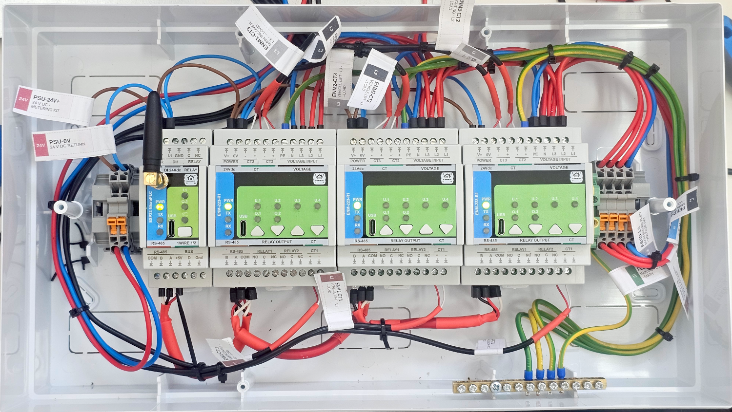
The problem everyone hits first: space
The most common complaint about circuit-level metering is not price. It is that nobody can fit it in the board. Sub-metering six, nine or sixteen circuits usually means either a stack of single-channel meters or a fistful of clamps with nowhere to land them.
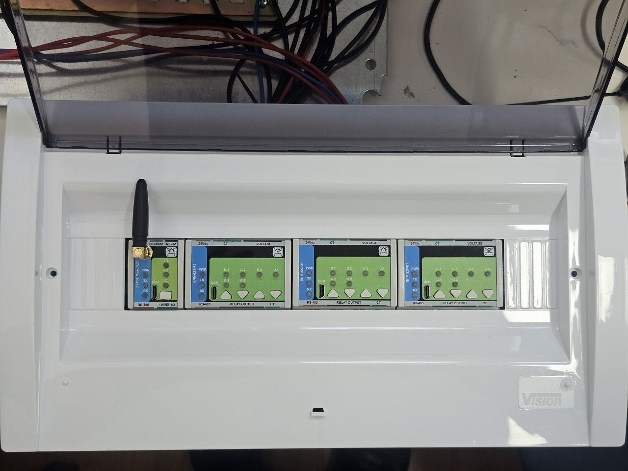
Nine channels here take four DIN modules — one controller and three three-phase meters, three CTs each. The clamps land on screw terminals inside the metering enclosure, which sits under the existing distribution board, so the CT leads are the only thing that crosses between the two. Adding channels later is another module on the same RS-485 pair, not a second system.
| Module | Channels | Measures |
|---|---|---|
| ENM #1 | CT1 / CT2 / CT3 | Main incomer, three phases |
| ENM #2 | CT1 / CT2 / CT3 | Vehicle lift, three phases |
| ENM #3 | CT1 / CT2 / CT3 | Compressor, lighting, socket circuits |
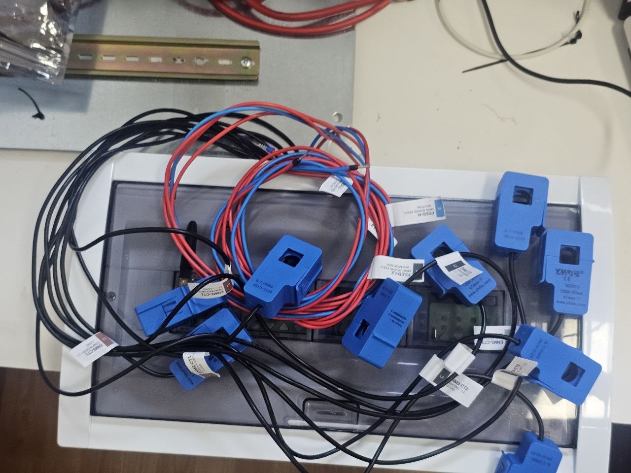
What makes these meters different
Each module is an autonomous instrument, not a sensor. An RP2350 with an ATM90E32AS metering front end, its own alarm engine (L1/L2/L3 and totals × alarm / warning / event, with an optional acknowledge latch) and two SPDT disconnect relays it drives itself. Voltage sag, overvoltage, phase loss, overcurrent, frequency drift and reverse phase sequence are detected inside the meter. Pull the network cable, switch off the server, unplug the controller — the meter keeps measuring and the relay still trips.
Power quality, not just kilowatt hours. Urms and Irms including neutral, signed active and reactive power, apparent power, power factor, phase angle, THD, frequency, board temperature, and import and export energy per phase and in total. Signed and per-phase matters the moment PV appears on site.
5 kV RMS isolation between the metering front end and the logic, with the analog domain on its own isolated supply. That is why a mains instrument can share an enclosure with 24 V, USB and RS-485.
Configured in a browser over USB-C, no driver and no app. Modbus address and baud, CT ratio and PGA, phase mapping, 3P4W or 3P3W, line frequency, calibration, alarm rules, relay and LED behaviour — all in WebConfig, stored in the module's own flash.
Standard Modbus RTU, and open. Hardware under CERN-OHL-W v2, firmware under MIT, the register map published. It works with our controller and equally with any Modbus master, HMI or SCADA already on site.
With our controller, zero integration work. The MicroPLC runs a ready-made ESPHome package: declare the meter once per Modbus address and every register arrives in Home Assistant as a named entity. No MQTT broker, no hand-written register map, no templating to get a number on screen.
How it compares to what people usually buy
| Typical cloud clamp system | Whole-house smart meter | DIY ESPHome board | ENM-223-R1 | |
|---|---|---|---|---|
| Circuit-level channels | many, one box | 1–3 | many | 3 per module, extend on the bus |
| Works with no cloud | often not | varies | yes | yes |
| Works with no server | no | no | no | yes — local alarms and relays |
| Disconnect relay on board | no | some | no | 2 SPDT per module |
| Power quality (THD, angle, PF) | rarely | rarely | no | yes |
| Ready product, no soldering | yes | yes | no | yes |
| Open firmware and register map | no | no | yes | yes |
| Protocol | vendor | vendor / P1 | yours | Modbus RTU |
The two columns people usually have to choose between are "finished but closed" and "open but self-assembled". This is the one that is both.
The job
A repair shop gets one electricity bill a month. It says what the building cost and nothing about what caused it, so every conversation about it is an argument between opinions.
The owner wants Home Assistant running the place eventually — protections in the switchboard, the compressor watched, cameras, lighting. The first stage was scoped as one panel that stands on its own: four modules, under the existing board, in an afternoon.
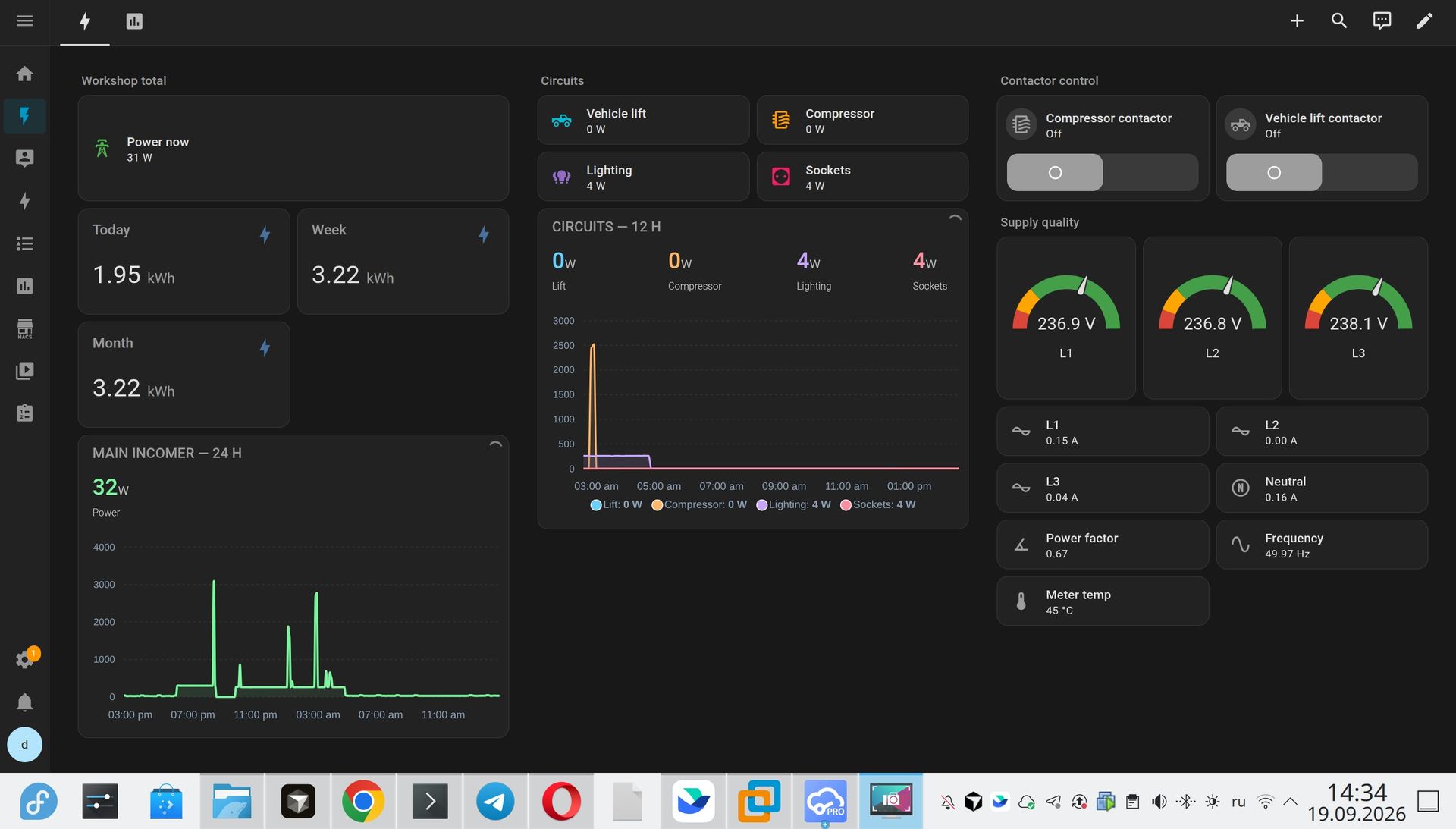
What the first day of sub-metering showed
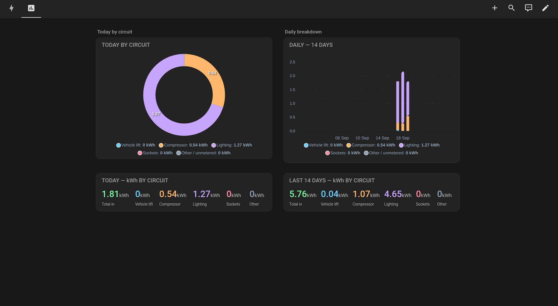
The shop had not opened yet, so the first full day is pure standby. That turned out to be the interesting part.
| Circuit | kWh | Share |
|---|---|---|
| Lighting | 2.09 | 84 % |
| Compressor | 0.35 | 14 % |
| Vehicle lift | 0.04 | 2 % |
| Sockets | ~0 | — |
| Total | 2.48 |
In an empty building the lights are not "nothing" — they are nearly everything. One timer away from being fixed, and invisible from the bill. This is the entire argument for splitting circuits instead of metering the total: a whole-house number would have shown 2.48 kWh and told you nothing.
Three-phase: the mistake that produces plausible wrong numbers
If you have ever seen one phase read negative, or a power factor that makes no sense, this is usually why. Inside the metering chip each current channel is paired with the voltage input of the same number: CT1 with L1, CT2 with L2, CT3 with L3. For a three-phase load that is automatic. For single-phase branches it is a hard constraint — three single-phase circuits on one meter have to sit on three different phases.
Get it wrong and you still get numbers. They look plausible. They are wrong, and not by a scale factor: the phase relationship is meaningless, so active power, reactive power and power factor are all garbage, and no arithmetic afterwards recovers them.
We got this wrong on this very job and redid the channel plan. Phase mapping is configurable in WebConfig, which covers the wiring you cannot change — but the channel plan itself is decided at the distribution board, with a phase tester, before anything is clamped. It is the sort of thing you should hear from your supplier before you order, not from a forum three weeks after.
channel plan is wrong.
What you are actually buying
Not a payback on kilowatt hours. In a shop with a bill in the low hundreds per month, the energy saved by knowing where it goes will not repay the hardware in any sensible time, and anyone who tells you otherwise is selling a spreadsheet.
What it does pay for:
Protection that depends on nothing else. One three-phase motor lost to a dropped phase or a sustained undervoltage costs more than the whole panel. The meter sees both and its own relay acts, server or no server.
Condition instead of consumption. A compressor with a leak in the ring main runs thirty percent longer for the same work, and that shows up in current long before it shows up in a bill. A failing bearing raises starting current. The useful sentence is not "you saved eight euros", it is "you did not lose two days without air".
Splitting one supply. Two bays or two tenants behind one meter, and the arguments end in month one.
Everything added later. The controller, the RS-485 bus and the 24 V rail are shared with every later stage. Amortise the panel across the whole system, not across the metering.
To be explicit: the alarm logic and relays are supplementary monitoring and control. They do not replace the protective devices an installation requires, and the relay drives a contactor coil — the motor is switched by the contactor, with its own motor protection.
The hardware
MicroPLC, three ENM-223-R1 three-phase meters and nine current transformers, with the Home Assistant configuration. The four modules are sold together as one kit — 9-Channel Energy Metering Kit, HM-KIT-ENM-9CH, 425 € excl. VAT. Individually: ENM-223-R1 and MicroPLC.
The full technical build — terminal-level wiring, the commissioning order and the Home Assistant configuration — is on Hackster: Nine Circuits, One Panel: Modbus Metering in Home Assistant.
Want the same in your panel? Tell us what you need to see and we will tell you how many channels and how many DIN modules it takes. To size it yourself, use the System Builder.