4–20 mA to 0–10 V: Reading Industrial Wind Sensors with the AIO-422-R1
The AIO-422-R1 takes 0–10 V. Industrial wind sensors put out 4–20 mA. One resistor bridges the two — but which resistor, and what does the arithmetic look like on the other side? Here is the whole chain: current loop conversion, wiring, ESPHome scaling, and a clean m/s reading in Home Assistant — including the value we got slightly wrong on the first build.
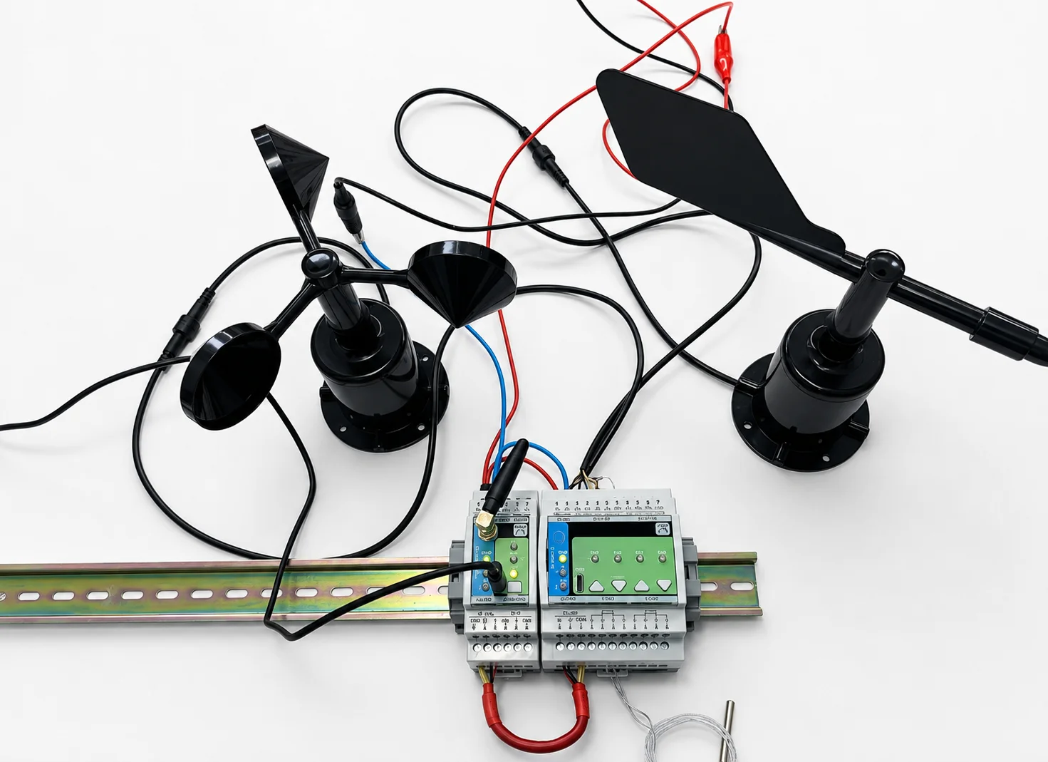
The short version. A weather mast — wind speed, wind direction, PT100 temperature — wired into an AIO-422-R1 and read by a MicroPLC over RS-485 Modbus RTU.
- The sensors are 4–20 mA; the AIO's analog inputs are 0–10 V, so each loop passes through a sense resistor.
- We first fitted 510 Ω, which puts 20 mA at 10.2 V — just above the input ceiling, so the top of the scale clips. 470 Ω is the value to fit.
- Scaling, loop-fault detection and temperature all run on the DIN rail. Home Assistant only draws the graphs.
1. The Build: Modbus Wind Sensors on a DIN Rail
Four DIN modules and a mast. No cloud, no vendor app, no bridge in between:
| Part | Role |
|---|---|
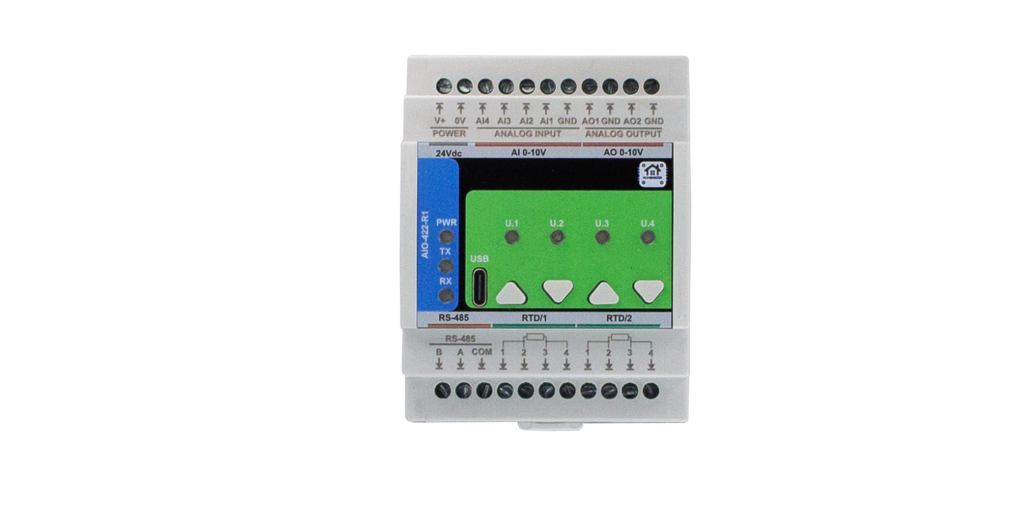
| AIO-422-R1 | Analog acquisition — 4 × AI 0–10 V (16-bit), 2 × RTD PT100/PT1000, 2 × AO 0–10 V. Modbus RTU slave on RS-485. |
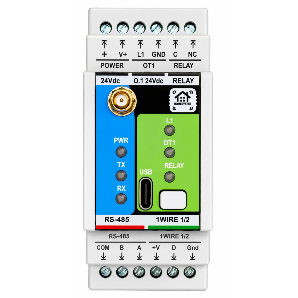
| MicroPLC | ESP32 controller running ESPHome. Modbus RTU master, and the place the scaling maths lives. |
| Wind speed sensor | ZTS-3000-FSJT-I20, 0–30 m/s, 4–20 mA, loop-powered from 24 V |
| Wind direction sensor | ZTS-3000-FXJT-I20, 0–360°, 4–20 mA, loop-powered from 24 V |
| RTD probe | PT100, 2-wire on this build |
| 2 × sense resistor | 470 Ω, 1 % metal film — one per current loop |
| 24 V DC supply | Feeds the modules and both sensor loops |
Channel assignment:
| Signal | AIO channel | Interface |
|---|---|---|
| Wind speed | AI2 | 4–20 mA via 470 Ω |
| Wind direction | AI4 | 4–20 mA via 470 Ω |
| Temperature | RTD1 | PT100, direct |
Takeaway: Three field signals, one module, one RS-485 pair back to the controller — the analog front end and the RTD front end are the same device, so there is nothing to daisy-chain between them.
2. Why 4–20 mA, and What the AIO-422-R1 Accepts
Settle this before ordering parts: the AIO-422-R1's analog inputs are 0–10 V. There is no current-input mode.
Its channels are voltage inputs with high input impedance (>100 kΩ) — right for a voltage sensor, and exactly what a current loop cannot drive on its own. Buy the 0–10 V variant of a sensor and you wire it straight in, skipping this entire article.
We bought the 4–20 mA variants anyway, for the two reasons that usually decide it:
- Cable length doesn't corrupt the reading. A current loop carries the same current at both ends; the volt drop along the run doesn't matter as long as the supply can push through it. A 0–10 V signal loses accuracy over a long run and picks up more noise on the way.
- A broken wire is detectable. 4 mA is the "live zero" — the bottom of the range is still current. Zero current is not a valid reading; it means the loop is open. A 0–10 V sensor reading 0 V could be a calm day or a cut cable, and nothing in the signal says which. We cash this in at §8.
Current loop conversion is one component: put a resistor in the loop's return path and measure the voltage across it. Ohm's law does the rest.
Takeaway: The AIO reads voltage only, so a 4–20 mA sensor needs an external sense resistor — but the live zero you get in exchange is worth the part.
3. Sizing the 4–20 mA Sense Resistor: Why 470 Ω
The sensor pushes 4–20 mA through your resistor, so:
V(4 mA)  = 0.004 × R      bottom of the sensor's range
V(20 mA) = 0.020 × R      top of the range — must stay under 10 V
Our first build used 510 Ω. That is where the arithmetic goes wrong:
| Resistor | At 4 mA | At 20 mA | Verdict |
|---|---|---|---|
| 510 Ω | 2.04 V | 10.20 V | Overshoots the 0–10 V input range — the top of the scale is unreadable |
| 470 Ω | 1.88 V | 9.40 V | Recommended. Standard value, 6 % headroom at full scale |
| 499 Ω (0.1 %) | 2.00 V | 9.98 V | Tidy round numbers, almost no headroom — precision option |
With 510 Ω on a 0–30 m/s sensor, everything above roughly 29.4 m/s lands past the top of the input range. On a domestic mast you may never see it; on a site where the top of the scale is the reading that matters, you lose exactly the event you installed the sensor for.
Two more things about that resistor:
- Tolerance is your accuracy. Its value scales every reading one for one — a 5 % resistor is a 5 % error before you measure anything. Use 1 % metal film, or 0.1 % if the numbers matter. Better still: measure the part you actually fitted and put that value into the config in §8.
- Power is a non-issue. 20 mA through 470 Ω is under 0.2 mW. Any ordinary part will do.
Takeaway: 470 Ω is the safest standard value, because it keeps the entire 4–20 mA range inside the AIO's 0–10 V input with headroom to spare.
4. Wiring the Current Loop
Both wind sensors are 2-wire loop-powered devices: one pair carries supply and signal. The loop runs 24 V+ → sensor → sense resistor → 0 V, and the AIO measures across the resistor.

Three rules for the run:
- Share the ground. The sensor supply's 0 V and the AIO's AGND must be the same node. The module measures across the resistor relative to its own analog ground; return the loop to a different 0 V and the reading drifts with everything else in the cabinet.
- Treat it as an analog run. Twisted pair per channel, shield bonded at the controller end only, away from power conductors, crossings at 90°. The AIO-422-R1 product page carries the full wiring reference and cable recommendations.
- RS-485 as usual. A → A, B → B, COM → COM, 120 Ω twisted pair, terminated at the ends of the run.
Takeaway: The sense resistor only measures correctly if the loop returns to the same ground the module measures against — a shared 0 V is not optional.
5. Configuring the Module in WebConfig — USB-C, No Drivers
The AIO is set up from a browser over USB-C using Web Serial. Nothing to install, no vendor tool, no licence: plug the module into a laptop and open WebConfig in Chrome or Edge.
What we set for this build:
- Modbus tab — address and baud rate. Address 3 at 19200 baud here; the module accepts addresses 1–247 and 9600–115200 baud. Whatever you pick must match the controller in §6.
- RTD tab — sensor type (PT100), wiring mode and reference resistor. RTD wiring is set in two places: field-board jumpers select 2/3/4-wire and PT100/PT1000, and WebConfig has to agree with them. Factory default is PT100, 2-wire.
- Analog I/O tab — live mV from AI1–AI4. This is how you sanity-check the resistor before writing a line of YAML: blow on the anemometer and watch the millivolts move.
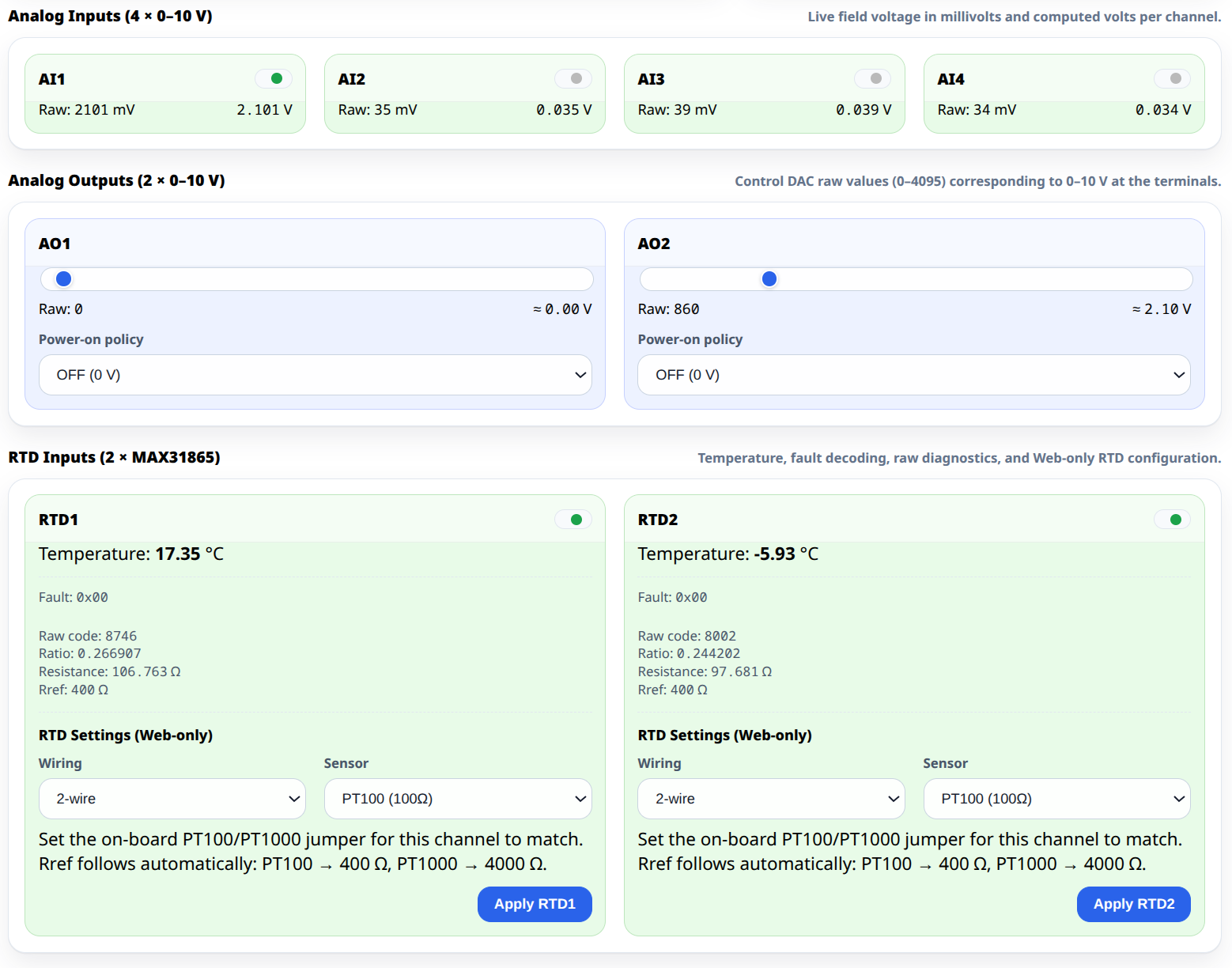
Configuration lives in the module's own flash (LittleFS) and survives a reboot and a power cut. The module comes up configured whether or not a controller is on the bus.
Takeaway: Verify the resistor in WebConfig's live mV view first — a scaling bug found in the browser is cheaper than one found in a lambda.
6. The Controller Side: Minimal ESPHome Config
The MicroPLC is the Modbus master. The integration is a UART, a Modbus bus and an imported package — no register list to write by hand:
uart:
  id: uart_modbus
  tx_pin: 17
  rx_pin: 16
  baud_rate: 19200        # must match the module's WebConfig setting
  parity: NONE
  stop_bits: 1

modbus:
  id: modbus_bus
  uart_id: uart_modbus
  turnaround_time: 100ms
  send_wait_time: 250ms

packages:
  aio1:
    url: https://github.com/isystemsautomation/homemaster-dev
    ref: main
    files:
      - path: AIO-422-R1/Firmware/v0.1.0/default_aio_422_r1_plc/default_aio_422_r1_plc.yaml
        vars:
          aio_prefix: "AIO#1"   # entity name prefix in Home Assistant
          aio_id: aio_1        # internal id, used by lambdas below
          aio_address: 3       # Modbus address set in WebConfig
    refresh: 1d
Do not leave out turnaround_time and send_wait_time. ESPHome 2026.7.0 raised the Modbus client defaults to 600 ms and 2000 ms. At a 600 ms turnaround the bus carries roughly 1.5 transactions per second whatever the UART speed, because the controller sits silent after every response. Two modules on one bus get sluggish; with three or more, one can stop being polled altogether — quietly, with no timeout and no CRC error in the log.
Three variables decide whether this works:
aio_addressandbaud_rate— must match WebConfig. Get either wrong and the module is simply silent.aio_prefix— cosmetic; prefixes entity names in Home Assistant.aio_id— not cosmetic. It is the handle every lambda uses, soaio_id: aio_1gives youaio_1_ai2,aio_1_ai4,aio_1_rtd1.
Takeaway: Twenty lines of YAML replace a hand-written Modbus register map — but on ESPHome 2026.7.0 and newer, the two timing values are mandatory, not optional.
7. What the ESPHome Package Gives You
Flash that and the module's entities reach Home Assistant over the ESPHome native API within seconds — no MQTT broker, no Modbus register mapping in Home Assistant, no converters:
| Entity | ESPHome id | Units |
|---|---|---|
| AI1–AI4 field voltage | aio_1_ai1 … aio_1_ai4 | mV, raw |
| RTD1 / RTD2 temperature | aio_1_rtd1, aio_1_rtd2 | °C, already scaled |
| AO0 / AO1 setpoint | — | slider, raw DAC counts 0–4095 |
Three details worth knowing:
- Analog inputs arrive as raw millivolts. The package deliberately does not guess what your sensor means — which is why §8 exists.
- Temperature needs none of that. RTD1 is already a °C sensor with one decimal, ready for the dashboard as it stands.
- A fuller variant exists.
default_aio_422_r1_plc_full.yamladds the module's four front-panel buttons and four LEDs as entities.
One thing is not in the package, and it is easy to assume otherwise: the module's four PID loops are configured in WebConfig and run on the module itself. That is the point of them — they keep running while the controller reboots.
Takeaway: The package is the difference between integrating a module and integrating a register map; everything except the sensor-specific scaling is already done.
8. Converting 4–20 mA to m/s in ESPHome
Derive the constants from the resistor you actually fitted, rather than hard-coding magic numbers. A different resistor then becomes a one-line change instead of a puzzle six months from now:
sensor:
  - platform: template
    name: "Wind Speed"
    id: wind_speed
    unit_of_measurement: "m/s"
    device_class: wind_speed
    state_class: measurement
    accuracy_decimals: 1
    update_interval: 1s
    lambda: |-
      const float R    = 470.0;        // measured value of the sense resistor, ohms
      const float ZERO =  4.0 * R;     //  4 mA -> mV, the sensor's live zero
      const float SPAN = 16.0 * R;     // 16 mA -> mV, the usable span

      float mv = id(aio_1_ai2).state;
      if (isnan(mv))          return {};    // no Modbus reply yet: stay unavailable
      if (mv < ZERO * 0.75)   return {};    // below live zero: broken loop, NOT calm weather

      float v = (mv - ZERO) * 30.0 / SPAN;  // 0-30 m/s sensor
      if (v < 0.0)  v = 0.0;
      if (v > 30.0) v = 30.0;
      return v;

  - platform: template
    name: "Wind Direction"
    id: wind_direction
    unit_of_measurement: "°"
    state_class: measurement
    icon: "mdi:compass-outline"
    accuracy_decimals: 0
    update_interval: 1s
    lambda: |-
      const float R    = 470.0;
      const float ZERO =  4.0 * R;
      const float SPAN = 16.0 * R;

      float mv = id(aio_1_ai4).state;
      if (isnan(mv))          return {};
      if (mv < ZERO * 0.75)   return {};

      float d = (mv - ZERO) * 360.0 / SPAN;  // 0-360 degrees
      if (d < 0.0)   d = 0.0;
      if (d > 360.0) d = 360.0;
      return d;
The two guard clauses matter more than the formula:
return {}publishes nothing, so the entity goes unavailable — which is the truth. Returning0.0, as the obvious first draft does, invents a reading: a dead sensor and a windless afternoon become the same number on the graph, and every automation downstream believes it.- The live-zero check is the payoff for choosing 4–20 mA. Below 4 mA there is no valid reading, so say so rather than smoothing it into the data.
Polling is every second, because that is what every HomeMaster ESPHome package does — 1 s interval, no command throttle, on every module in the range. You are not tuning a cadence here.
Takeaway: Scale from the measured resistor value, and let a broken loop read unavailable rather than zero — a fake zero is worse than no data.
9. Gotchas That Will Fool You
- Never average wind direction. It is circular: 359° and 1° are two degrees apart, yet their arithmetic mean is 180° — a south wind invented out of two northerlies. Any sliding average, median or smoothing filter on raw degrees does this, and the result looks plausible enough to survive review. Average the sine and cosine components and take the arctangent, or leave the reading instantaneous.
- The resistor is part of your calibration. Nominal 470 Ω parts are not 470 Ω. Measure yours, put the measured value into
R, and the scale error disappears for free. - The module is a cabinet device, the mast is not. The AIO-422-R1 is IP20 and rated 0…+40 °C — it belongs in a ventilated, heated enclosure. The sensors live outdoors and are rated for it; the module is not, and an unheated outbuilding in a Romanian January is outside its range.
- 2-wire PT100 puts the cable in the measurement. Lead resistance adds directly to the sensed resistance — roughly 0.39 Ω of cable reads as a whole extra degree. Fine for a short run inside the cabinet, which is what we had. For anything longer, move to 3-wire: field-board jumpers and the WebConfig RTD tab both support it, and both must change together.
- Baud and address mismatches are silent. A wrong
aio_addressor a mismatchedbaud_rateproduces no error worth the name — the module just never answers. Check the Modbus tab in WebConfig before debugging anything else.
Takeaway: Most of what will waste your afternoon is not the analog chain — it is a circular average, an unmeasured resistor or a baud rate nobody checked.
10. Where the Logic Actually Lives
Everything above runs on the DIN rail:
- Millivolts become metres per second in the MicroPLC.
- Resistance becomes °C on the AIO-422-R1.
- PID loops, if used, run on the module with their settings in its own flash.
Home Assistant receives finished values in real units and does what it is good at: dashboards, history, cross-system automations. The controller does the thinking, the server visualises.
That split answers the question every self-hosted setup eventually faces — what happens while the server is rebooting? Here, acquisition and local logic don't notice. And because the modules speak plain Modbus RTU rather than a proprietary bus, none of this is locked to HomeMaster: the same AIO-422-R1 answers any Modbus master on the wire, including a third-party PLC or a SCADA system, if the rail ever ends up in a different system.
There is a general rule underneath this particular mast. Convert signals as close to the hardware as you can, and detect failures before the data ever reaches the server. A resistor chosen with headroom, a live-zero check in a lambda and a scale factor derived from a measured part are three decisions made on the rail — and each one removes a class of error that Home Assistant, working from a number that already arrived, has no way to catch. A dashboard cannot tell a broken loop from calm weather. The module can.
Takeaway: Put measurement logic where the measurement happens. Home Assistant should visualise data, not be the place where you find out the data was wrong.