Driving Roller Shutters from Home Assistant with a Relay Pair and Interlock
A shutter motor has two windings and one absolute rule: never energise both at once. Everything else about automating shutters — the buttons, the timing, the position in the app — is built on top of that rule being enforced by something that cannot forget it, which is not the same thing as being enforced by an automation.
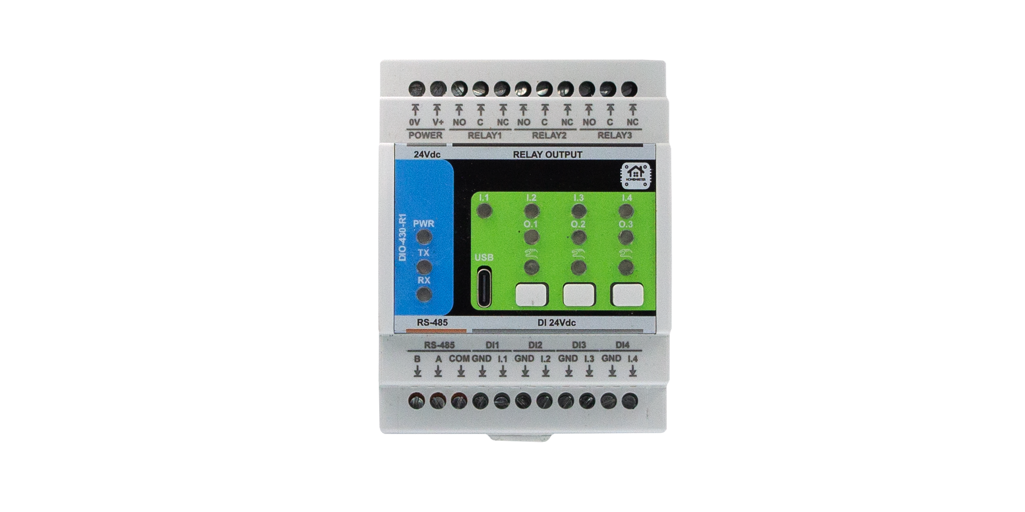
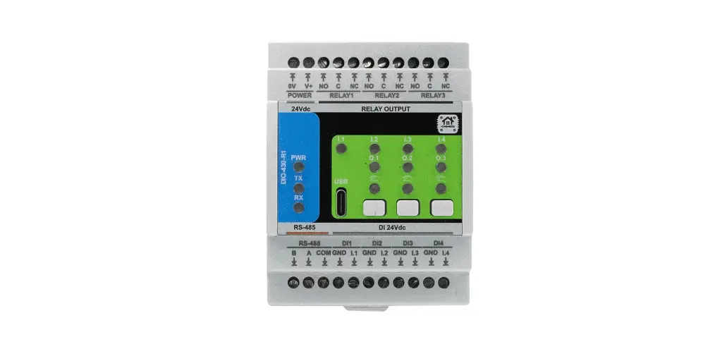
The short version. One shutter needs two relays — up and down — and a hardware-enforced guarantee that they are never closed together, with a pause between reversals so the motor stops before it is asked to run the other way. On the DIO-430-R1 that guarantee is a setting on the module, not an automation on a server: a mutually exclusive relay pair with a configurable dead time. Add an auto-off timer as a travel timeout, decide the power-on state deliberately, and remember that without an encoder there is no such thing as a real position — only a stopwatch.
1. A Shutter Is Not a Lamp
A lamp has one state that matters and no way to hurt itself. A tubular shutter motor is a different animal in three ways, and each one changes the wiring.
It has two directions, and they are two separate windings. Common neutral, one live for up, one live for down. Energise the up winding and it runs up; energise the down winding and it runs down; energise both and, on most motors, you have destroyed something — the winding, the capacitor, or the motor's own end switches.
It stops itself. Mechanical or electronic end stops inside the motor cut the power at the top and the bottom of travel. That is deliberate and it is why you do not need position feedback to avoid damage — but it also means the control side has no idea when the motor stopped, only when it was told to start.
It is an inductive load with real inrush. A motor starting is not a resistive load, and the contact that breaks it takes the arc. That is the ordinary case for relay contacts and it is why the ratings matter, which comes up in section 6.
2. Two Relays, and Why Both-On Is Not a Fault But a Failure
The naive way to build this is two independent relay channels and an automation that promises never to turn both on. That promise is worth exactly as much as the thing making it.
Consider what has to hold for the promise to be kept: the automation is correct, the server is running, the network delivered both commands in the right order, no one pressed the wall button while a scene was executing, no one wrote a second automation last year that also touches these relays, and nothing crashed halfway through. Every one of those is fine on a Tuesday. The one time they are not is the time the motor is destroyed.
Interlock moves the guarantee down to the device. Two relays are declared a mutually exclusive pair on the module: closing one opens the other, unconditionally, evaluated in the module's own loop regardless of what the bus or the server just asked for. There is no state of the system in which both are closed, because the module does not have that state.
The dead time is the second half of it. Reversing a running motor instantly is bad even if the two contacts never overlap: the motor is still turning, the contact is still hot, and the inrush of starting the opposite winding lands on top of the back-EMF of the one just released. A configurable pause with both contacts open lets the motor stop before it is asked to do anything else. It costs a fraction of a second and it costs nothing in comfort.
3. What That Looks Like in Configuration
Three settings on one screen do the whole job.
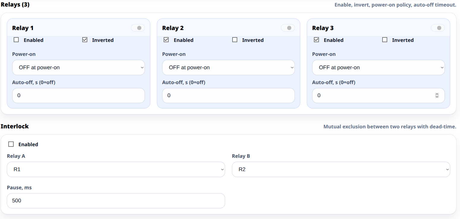
The interlock pair. Declare which two relays are the pair and how long the dead time is. That is the safety property, and once it is set, nothing above it can violate it.
Auto-off as a travel timeout. A shutter takes a known time to travel end to end — typically some tens of seconds. Set the auto-off a little longer than that and the relay switches itself off afterwards, unconditionally. This matters more than it looks: if a stop command is ever lost, the motor is not left energised against its end stop waiting for a network to recover.
Power-on state. When the panel is energised — after an outage, after work in the consumer unit — what should the shutters do? The honest default is nothing: both relays off, shutters stay where they are. It is worth choosing that on purpose rather than discovering that every shutter in the house tries to move at seven in the morning after a power cut.
4. Wall Buttons, and Why They Belong on the Same Module
The module has four digital inputs alongside its relays, and the natural thing is to put the shutter's own wall buttons on them.
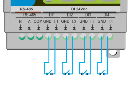
Two buttons, up and down, is the conventional arrangement, and the module's press logic gives you the rest: a short press to run, a second press to stop, a long press for continuous travel. Because the inputs and the relays are on the same device, that behaviour is a local rule — the buttons keep working with the controller off, the server down, or the network unplugged, which for a shutter is not a nice-to-have. A stuck shutter on a hot afternoon is the kind of thing people remember about a smart home.
Which rules belong on the module and which belong upstairs is the whole subject of what still works when Home Assistant is down. Shutters are close to the top of the list of things that should not wait for a server.
5. Counting: Three Relays Means One Shutter Per Module
Here is the arithmetic that surprises people. A module has three relays. A shutter needs two. So one module drives one shutter, with one relay left over for something else — an awning, a light, a contactor coil.
Two shutters is two modules. Six shutters is six modules, or eighteen relay channels of which twelve are used. That is the real cost of motorised shutters in a panel-based system, and it is better to know it while sizing the enclosure than while ordering the second batch.
The spare relay is genuinely useful, though, and worth planning for rather than wasting. On a window group it often ends up driving the room's lighting circuit, which means the shutter module and the light it shares a room with are the same device — and therefore the same local rule.
To turn a window count into a module count and a panel width, the System Builder does it directly.
6. Ratings, Because a Motor Is Not a Lamp Either
Relay outputs on these modules are rated 3 A at 250 V AC resistive, with system limits of 750 VA and 90 W at 30 V DC, and they are not internally fused.
A single domestic tubular shutter motor is typically well inside that on running current. What is not inside it is the assumption that running current is the whole story: the motor is inductive, starting draws more than running, and the contact takes an arc on every break. A relay switching one small motor a few times a day is doing an ordinary job. The same relay switching a group of motors together, or a larger motor, is not.
So the rule is the usual one: one motor per relay pair, and anything bigger or ganged goes through a contactor, with the module switching the coil. The full treatment of that decision, including what inrush actually does to a contact, is in how many relay channels you need and what should switch the load.
And the protection: the shutter circuit gets its overcurrent device in the panel, like any other circuit. Nothing about the relay changes that.
7. The Honest Bit About Position
Home Assistant will happily show a shutter as 70 % closed. It is worth understanding what that number is.
With relay control and no encoder, position is a stopwatch. The system knows how long a full travel takes, it knows how long it has been running, and it infers the rest. There is no feedback from the motor — the end stops are internal and silent, and a relay cannot tell whether the shutter moved or whether the slats were jammed by ice.
What that means in practice:
- Intermediate positions drift. Small timing errors accumulate over a day of partial movements.
- Full travel resets it. Sending the shutter all the way to an end stop re-synchronises the estimate, which is why a nightly full close is a good habit rather than a waste.
- An obstruction is invisible. The system reports what it commanded, not what happened.
None of this is a defect of the module — it is what relay control is. If a project genuinely needs true position, that requires a motor with feedback and a different control strategy, and it is worth knowing that before promising anyone a percentage.
8. What This Is Not
Not a safety device. No obstruction detection, no force limiting, no safety rating. Motorised shutters near people and pets are covered by their own standards, and a relay module is not part of that story.
Not position feedback. Section 7.
Not a substitute for the motor's own end stops. The auto-off timer is a backstop for a lost command, not a way to stop travel. Setting the shutter's limits is done on the motor.
Not fused, and not rated for ganged motors. Section 6.
Not rated for outdoors. IP20, 0 °C to +40 °C — the module lives in the panel, not in the shutter box.
9. The Takeaway
Automating shutters is mostly one decision made correctly: the guarantee that both directions are never live at the same time has to sit in hardware, below anything that can be reconfigured, crash or be forgotten. Once it does, everything above it is free — buttons, scenes, sun-tracking, a nightly close — because none of it can break the motor.
After that it is arithmetic. Two relays per shutter, three relays per module, one shutter per module with a spare. A travel timeout so a lost command cannot leave a motor energised. A deliberate power-on state. And an honest description of what the percentage in the app really is.
For the wiring that has to be in place before any of this, see connecting dozens of wired sensors, and for the bus that ties the modules together, RS-485 and Modbus in ESPHome.