RS-485 and Modbus in ESPHome: Wiring, Termination and Why It Times Out
A Modbus bus either works perfectly or does not work at all, and the difference is almost never the software. It is two wires that got swapped, a common return nobody connected, two devices claiming the same address, or a terminator in the wrong place. Here is the wiring, the settings, and the fault list in the order the faults actually happen.
The short version. RS-485 is the electrical layer — a differential pair plus a common return. Modbus RTU is the protocol riding on it. Most "it times out" reports come down to six things: A and B swapped, COM not connected, duplicate addresses, mismatched baud rate, termination missing or fitted in too many places, and a star topology where a daisy chain belongs. Work through them in that order and the bus usually comes up in ten minutes. The one thing worth knowing before you start: the terminal order is not the same on every module, so read the silkscreen instead of copying the module next to it.
1. Two Different Things With One Name
Half the confusion in this subject comes from treating RS-485 and Modbus as one thing. They are two layers, and they fail differently.
RS-485 is electrical. It defines how a bit is put on a wire: a differential pair, where the signal is the difference in voltage between two conductors rather than the voltage of one conductor against ground. That is the entire trick, and it is why the bus tolerates a noisy cabinet — interference lands on both conductors roughly equally and cancels out in the subtraction. It is also why the pair must actually be a twisted pair, and why the two conductors must not be swapped.
Modbus RTU is a protocol. It defines who may speak, when, and what the bytes mean: one master polls, slaves answer when addressed, each frame carries an address and a checksum. Modbus does not care about cable. RS-485 does not care about registers.
The practical value of keeping them apart is diagnostic. Electrical problems affect every device on the bus and usually all at once. Protocol problems — a wrong address, a wrong register, a wrong data type — affect one device while the rest carry on. That single observation narrows most faults in half a minute.
2. Three Wires, and the Third One Is Not Optional
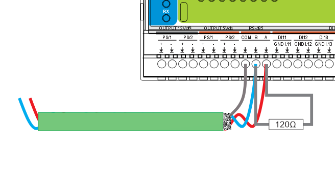
The bus needs A, B and a common return, usually labelled COM. Two of those are obvious and the third gets skipped constantly.
Differential signalling measures the difference between A and B, but the receivers still have to see both conductors within a voltage range they can work with. That range is relative to their own ground. If two devices sit on separate supplies with no common reference, nothing stops the whole pair drifting outside it — and then the bus works, mostly, until the day it does not, in a way that looks completely random.
So COM goes to every node. Not to earth at every node — to the bus common, carried along with the pair, one conductor of the same cable.
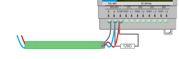
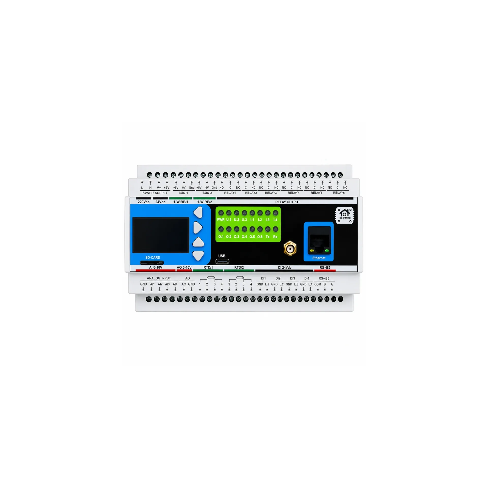
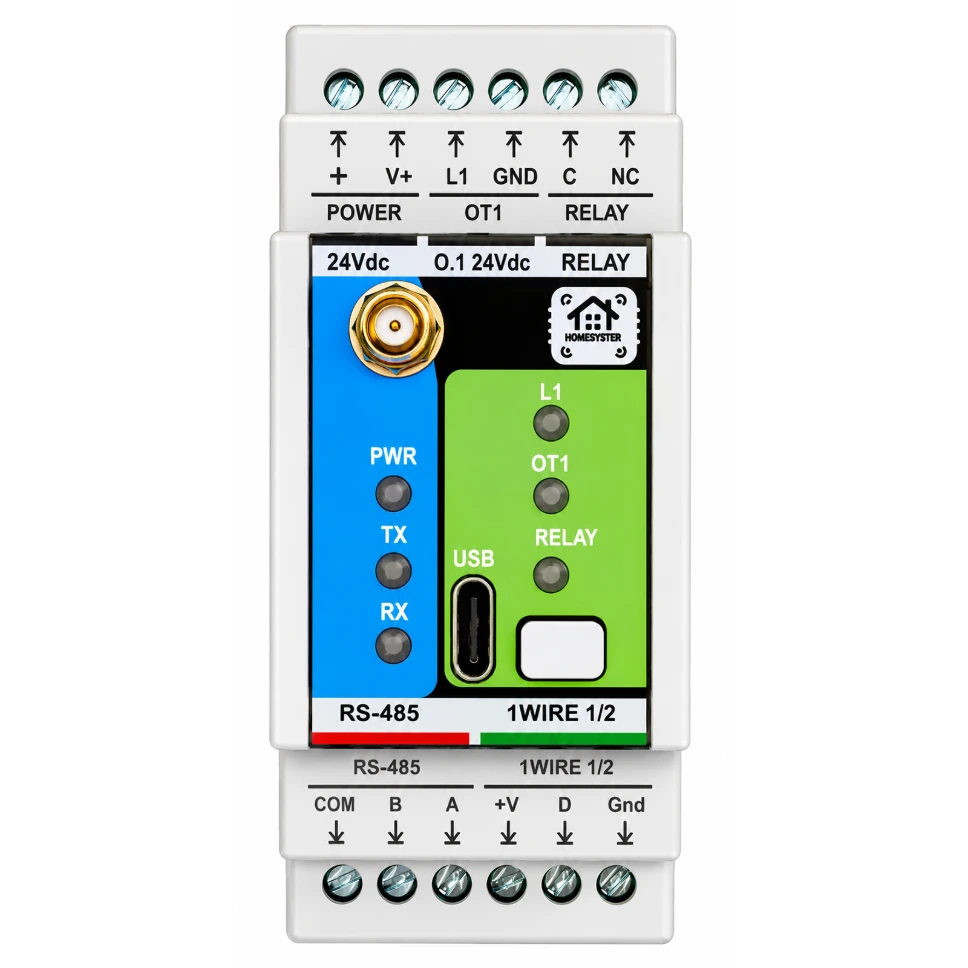
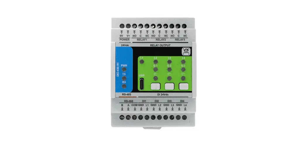
Read the silkscreen on each module. The order in which A, B and COM appear on the terminal block is not identical across the range — on some modules it is COM, B, A and on others B, A, COM. Copying the wiring pattern from the module beside it, rather than reading the labels, is one of the most common ways to end up with a swapped pair on exactly one node.
Use a proper cable. One twisted pair for A and B, plus a conductor for COM. Untwisted flat cable will often appear to work on a short run in a quiet cabinet and then fail once the run is long or a contactor starts switching next to it — which makes it one of the worst faults to diagnose, because it is intermittent by nature.
3. Topology: A Chain, Not a Star
RS-485 is a chain. The cable leaves the master, arrives at a node, leaves that node, arrives at the next, and so on to the last device. Two ends, one line.
What it is not is a star. Running a separate spur from a central point to each module is the wiring pattern people bring with them from Ethernet, and it produces reflections that get worse with length and speed — the classic symptom being a bus that works at 9600 and falls apart at 115200.
Termination goes at the two physical ends of the line, and nowhere else. A 120 Ω resistor across A and B at each end absorbs the signal instead of letting it bounce back. Fitting one at every module is a common and understandable mistake — it loads the bus down until the drivers cannot produce a clean signal any more, which looks exactly like a cable fault.
Short spurs off the main line are tolerable; long ones are not. If a module has to sit away from the run, keep the stub as short as you can and accept that a long spur is borrowing trouble from the same physics as the star.
4. Addresses, Baud Rate and One Master
Three settings, and all three have to agree across the whole bus.
One master. Modbus RTU has exactly one device that initiates conversation. On a HomeMaster bus that is the MiniPLC or MicroPLC running ESPHome. Everything else answers when spoken to.
Unique addresses. Every slave needs its own. Two modules on the same address is the fault that produces the strangest symptoms — both answer at once, the frames collide, and what the master sees is corruption that comes and goes depending on which registers it happens to be reading.
The same baud rate everywhere. Obvious in principle, easy to get wrong in practice when a module has been on the bench with different settings and goes into the panel without being checked.
All three are set on the module itself, in the browser over USB-C, and stored on the device — so a module carries its identity with it rather than being told who it is by the controller.
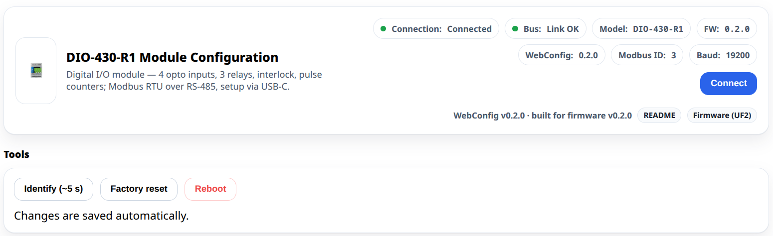
That identify button is worth knowing about before you need it. In a panel with eight identical grey modules, having one of them flash on command is faster than tracing a cable.
5. Why It Times Out — In Order of Likelihood
When a bus does not come up, resist the urge to change settings at random. Go down this list; it is roughly ordered by how often each one turns out to be the answer.
| # | Cause | What it looks like |
|---|---|---|
| 1 | A and B swapped on one node | Everything works except that one module — or nothing works, if it is the master |
| 2 | COM not connected | Works on the bench, intermittent in the building, worse when loads switch |
| 3 | Two modules on the same address | Random corruption, values that jump between two devices' data |
| 4 | Baud rate mismatch on one module | That module never answers, the rest are fine |
| 5 | No terminator, or one at every node | Fine at 9600, unusable at 115200; errors rise with cable length |
| 6 | Star topology or a long stub | Same as above, and it gets worse every time the bus is extended |
| 7 | Untwisted or unshielded cable near power wiring | Errors correlate with something switching on |
| 8 | Polling interval or response timeout too aggressive | Occasional misses under load rather than a dead bus |
| 9 | Ground potential difference between buildings | Works, then damages a port — see section 7 |
Two habits that shorten this list dramatically. First, bring the bus up with one module at a time: connect the master and one slave, confirm it answers, then add the next. A bus that is built up one node at a time tells you exactly which node broke it. Second, if it worked yesterday, ask what changed physically — a module swapped, a cable moved, a new device added — before touching any configuration.
6. What the Link Indicator Tells You, and What It Does Not
The modules show a bus link state, and on the DIO-430-R1 the timeout behind it is configurable — the Link timeout field, described in the interface as "No Modbus traffic for this long → bus link lost".
Read that literally, because it is precise. It reports that the module has not heard traffic recently. It is a diagnostic and an indicator: it drives the link LED and a status bit the master can read once it comes back. It does not change any output. There is no fail-safe behaviour attached to it — relays hold their state and any rules stored on the module carry on running. Which is usually what you want in a building, but it is worth knowing rather than assuming, and it is covered properly in what still works when Home Assistant is down.
7. Isolation: What You Have and What You Do Not
This is the section to read before running a cable between buildings.
The RS-485 front end on HomeMaster controllers and modules has transient protection — TVS diodes, resettable fuses, a common-mode choke and fail-safe biasing. That protects against surges and keeps the line in a defined state when no one is driving it.
It is not galvanic isolation. There is a conductive path between the bus and the module's own supply reference, and that matters the moment two ends of the bus sit in electrical installations with different earthing references — a separate building, an outbuilding, a utility meter cabinet, a garage on its own supply. The potential difference between those references does not care that your data is differential.
Where the bus crosses that kind of boundary, fit an external galvanically isolated RS-485 interface at the boundary. Inside one cabinet, on one installation, with COM carried to every node, the built-in protection is what the design assumes.
8. How It Reaches Home Assistant
The controller does two jobs at once. On the bus it is the Modbus master, polling each slave in turn. On the network it is an ESPHome device talking to Home Assistant over the native API — which means entities appear by themselves, with no MQTT broker in the middle and no register map maintained by hand inside Home Assistant.
That division is worth keeping in mind when something misbehaves. If a value is wrong in Home Assistant but right in the module's own browser interface, the problem is above the bus. If it is wrong in both, the problem is the bus or the module. The web interface over USB-C is, in effect, a second opinion that does not involve any of the network.
It also means the bus is a standard one, not a private protocol. A module speaks Modbus RTU whether the master is our controller, somebody else's PLC or a SCADA package — which is the practical form the phrase "no vendor lock-in" takes.
9. A Ten-Minute Commissioning Routine
Doing this in order, once, is faster than debugging later.
- Before anything goes in the panel, connect each module over USB-C and set its Modbus address and baud rate. Write the address on the module with a label. Future you will not remember.
- Wire the chain, module to module, reading the silkscreen on each one for the A, B and COM positions rather than copying the neighbour.
- Fit exactly two terminators, at the two physical ends of the line.
- Power up and bring nodes online one at a time. Confirm each answers before adding the next.
- Check the link indicator on each module, and use identify to confirm which physical module is which.
- Only then connect the controller to the network and look at Home Assistant.
- Write down the address map — module, address, what it controls. On paper, in the panel.
Step 7 is the one that feels unnecessary and is the one that saves an afternoon in three years, when somebody adds a module and needs to know which addresses are free.
10. What This Is Not
Not a claim that wired beats wireless. A wired bus is deterministic and lives in the cabinet; a radio protocol reaches places no cable will. They solve different problems, and the useful comparison is where the decision is made, not which medium is superior.
Not galvanically isolated. See section 7. Transient protection is not isolation.
Not a substitute for reading the register map. Modbus interoperability means the framing is standard. What lives at which register, in which scaling, is per product and documented per product.
Not a network. One master, one conversation at a time, deterministic by design. That is a feature in a panel and a limitation everywhere else.
11. The Takeaway
An RS-485 bus is unforgiving in a very specific way: it has almost no partial states. It either carries frames cleanly or it produces nonsense, and the causes of the nonsense are a short, boring list that has not changed in decades.
Swapped pair, missing common, duplicate address, wrong baud, wrong termination, wrong topology. Six things. Check them in that order, add nodes one at a time, label the addresses, and the bus stops being the mysterious part of the installation and becomes the part you never think about again.
For what runs on top of the bus once it is up, see connecting dozens of wired sensors, and for how the layers divide up, the platform overview.