How Many Relay Channels You Need — and What Should Switch the Load
Two questions decide the relay part of a panel, and people usually answer only the first. How many channels: that is arithmetic. What each channel is allowed to switch: that is where the number on the datasheet gets misread, because the relay inside is rated for far more than the module is.
The short version. Across the HomeMaster range a relay output is rated 3 A at 250 V AC resistive, with system limits of 750 VA at 250 V AC and 90 W at 30 V DC. The relay component fitted on the board is rated higher, and that higher number is the one that gets quoted and the one that will get you in trouble — it does not apply to the module, because the tracks, the terminals and the compliance testing are what set the limit. Outputs are not internally fused. Anything inductive, anything with real inrush and anything above 3 A gets a contactor, and the module switches the contactor coil.
1. The Two Numbers, and Which One Is Yours
Open the documentation for almost any DIN-rail relay module and you will find two current ratings that differ by a factor of four or five. Both are true. Only one of them is about the product you bought.
The component rating belongs to the relay itself — the small sealed box soldered to the board. It is what the relay manufacturer measured on their own test fixture, with their own terminals, under their own conditions.
The module rating is what the finished device is allowed to switch. It accounts for the copper on the printed circuit board, the screw terminals, the spacing between conductors, the heat rise inside a plastic enclosure sitting shoulder to shoulder with other modules on a rail, and the conditions under which the whole thing was tested for compliance.
The module rating is always the lower one, and it is the only one that means anything to an installer. For HomeMaster modules with relay outputs it is:
| Limit | Value | What it constrains |
|---|---|---|
| Rated load, AC | 3 A at 250 V AC, resistive | The current through the contact |
| Max load at 250 V AC | 750 VA | Apparent power — the one that matters for anything reactive |
| Max load at 30 V DC | 90 W | DC switching, where there is no zero crossing to help |
| Internal fuse | None | Protection is the panel's job, not the module's |
Those three numbers are consistent: 3 A × 250 V is 750 VA, and 90 W at 30 V is 3 A again. The limit is the contact, expressed three ways for three situations.
2. Why 750 VA and Not 750 W
The AC limit is given in volt-amperes rather than watts, and that is not pedantry.
For a resistive load — a heater, an incandescent lamp — volt-amperes and watts are the same thing and the distinction never comes up. For anything with a coil or a capacitor in it, they are not. A motor drawing 3 A at 230 V is presenting 690 VA to the contact regardless of how much real work it is doing, because the contact has to carry the whole current, including the part that is sloshing back and forth rather than being converted to anything useful.
So the practical reading is: size against the current the contact will actually carry, not against the wattage printed on the appliance. A 500 W motor is not a 500 VA load, and the difference is exactly the margin you thought you had.
3. What Actually Destroys Relay Contacts
Steady-state current is rarely what kills a relay. Three other things do.
Inrush. Many modern loads draw a brief current far above their running current at the instant of switch-on. An electronic LED driver charges its input capacitor through what is effectively a short circuit for a fraction of a cycle. A toroidal transformer can pull many times its rated current on the first half-cycle depending on where in the waveform the contact closed. The steady current might be 0.4 A; the peak might be twenty times that. The contact sees the peak.
Inductive break. When a contact opens on an inductive load — a motor, a contactor coil, a solenoid valve — the collapsing magnetic field tries to keep the current flowing and does so by striking an arc across the opening gap. That arc is what erodes the contact material. It is also why DC is harsher than AC: an AC arc is extinguished naturally a hundred times a second as the current passes through zero, and a DC arc has no such help. That is why the DC limit is a separate, lower number.
Welding. The end state of the two above. Enough inrush or enough arcing, often enough, and the contact material fuses. A welded relay is worse than a dead one: the module reports the state it commanded, the load stays energised, and nothing in the system knows.
The mitigations are old and boring and they work: an RC snubber across an inductive load, a varistor for surge, and a contactor when the load is beyond what a small contact should be doing at all.
4. When the Answer Is a Contactor
The rule of thumb is short: if the load is inductive, has significant inrush, or approaches 3 A, the module should not switch it directly. It should switch a contactor coil, and the contactor should switch the load.
This is not a workaround, it is the normal shape of a control panel. A contactor is a component designed to be destroyed slowly by exactly the abuse described above, it is cheap, it is replaceable in two minutes without touching the automation, and its coil is a small, well-behaved load — typically a few VA, well inside what a relay output is comfortable with.
5. What to Switch Directly and What Not To
A working shortlist. Where a load is borderline, the honest answer is to measure the inrush rather than reason about it, but this covers most of a house.
| Load | Directly? | Why |
|---|---|---|
| Incandescent or halogen lighting, small | Yes, within 3 A | Resistive; inrush is modest and brief |
| Resistive heating element, small | Yes, within 3 A | Purely resistive, no inductive break |
| A few LED lamps on a domestic circuit | Usually | Small drivers, but count them — inrush adds up |
| A full LED lighting circuit | Contactor | Many drivers charging at once is a large, very short peak |
| Valve actuator, small solenoid | Usually, with a snubber | Inductive; the break is what needs help |
| Circulation pump | Contactor | Motor: inrush plus inductive break |
| Immersion heater, electric radiator | Contactor | Current well beyond 3 A |
| Anything three-phase | Contactor | The relay is a single-pole device |
| Another contactor's coil | Yes | Exactly what the output is for |
One note on the middle rows: "usually" means the load is inside the ratings on paper and the failure mode is wear rather than immediate damage. A relay switching a marginal load will work for a year and then stop working, which is a worse outcome than one that never worked at all.
6. Counting Channels
Now the easier half of the question. Relay outputs across the range:
| Module | Relays | What it is for |
|---|---|---|
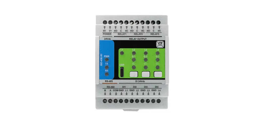
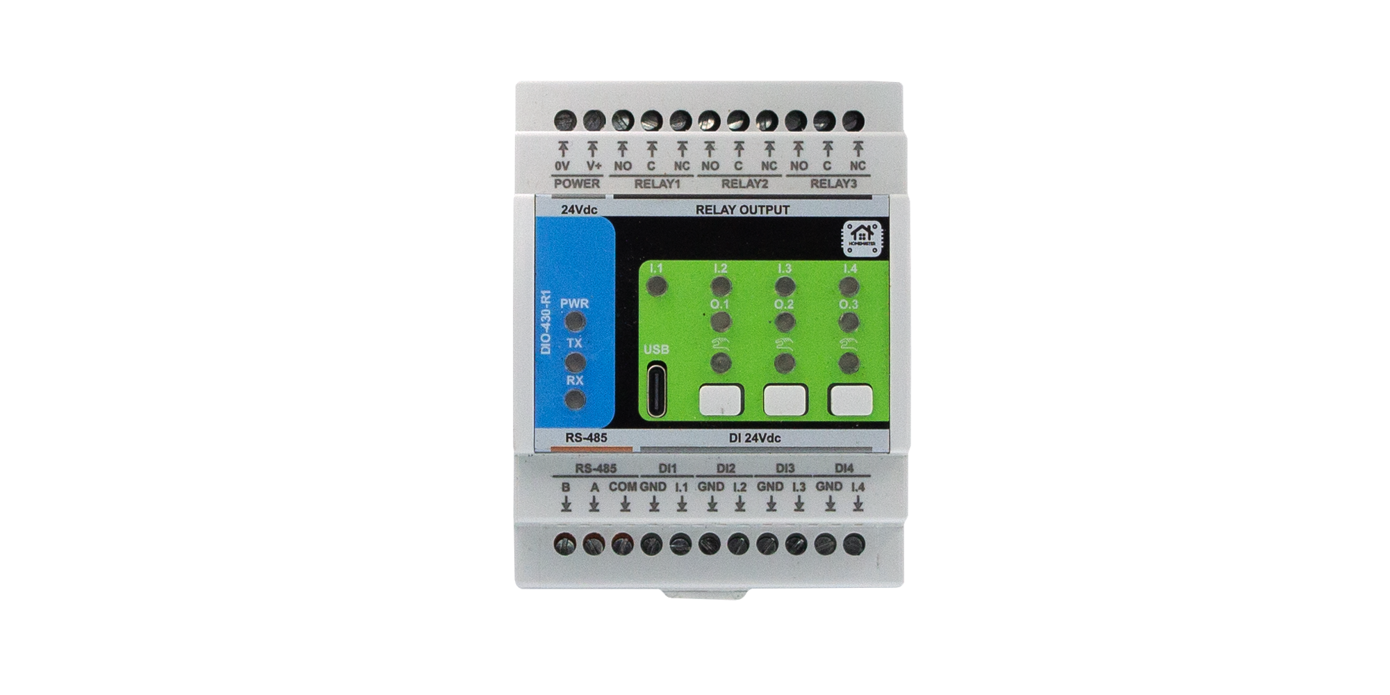
| DIO-430-R1 | 3 SPDT | General switching, with four digital inputs alongside |
| ALM-173-R1 | 3 SPDT | Sounder and alarm outputs, with seventeen zone inputs |
| WLD-521-R1 | 2 SPDT | Valve control alongside leak and water inputs |
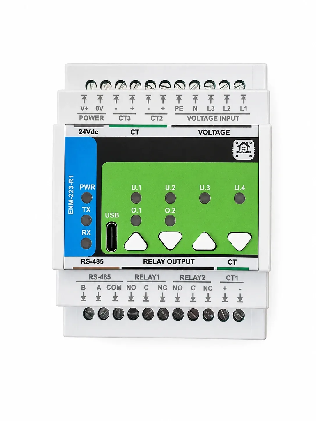
| ENM-223-R1 | 2 SPDT | Threshold-driven load shedding |
SPDT means changeover: COM, NO and NC. That matters more than it sounds. A changeover contact lets you choose whether the load is energised when the relay is active or when it is idle — which is how you decide what happens on a power failure, before any configuration is involved.
Count switched circuits, not rooms. Every lighting group, every pump, every valve, every contactor coil is one relay. Three per module goes faster than people expect: a modest ground floor with hall, kitchen, living room and outside lighting is already four.
Two arithmetic points worth knowing before ordering. First, relays come attached to inputs — a DIO brings four digital inputs with its three relays, and if what you need is only relays then some of those inputs go unused. Second, a bidirectional load costs two relays, not one, which is the subject of the next section.
7. Bidirectional Loads and the Dead Time
Anything that runs in two directions from one motor — a roller shutter, a valve actuator, a gate — needs two relays: one for each direction. And it needs a guarantee that both are never energised at once, because on most such motors that is not a fault condition, it is destruction.
The DIO-430-R1 handles this on the module: two relays can be declared a mutually exclusive pair with a dead-time pause between them, so a reversal always passes through a defined interval with both contacts open. The pause is not cosmetic — it gives the motor time to stop before it is asked to run the other way, and it keeps the two contacts from ever overlapping during transition.
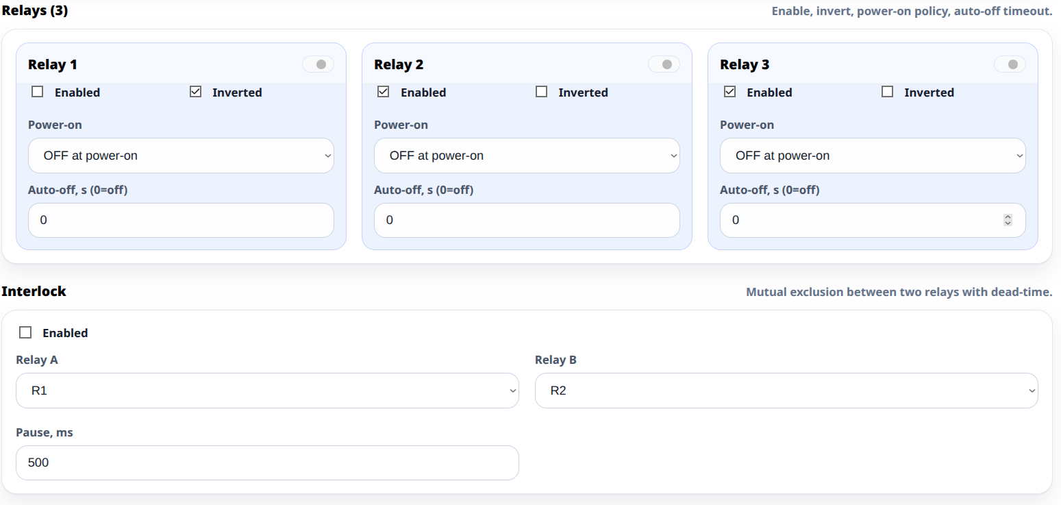
Two further settings on the same screen matter for this kind of load. Auto-off switches a relay back off after a set time, which for a shutter is a travel timeout — the motor is never left energised because a command was missed. Power-on state decides what happens when the panel is energised, which for anything that moves is a decision to make deliberately rather than inherit.
8. Protection Is the Panel's Job
Worth stating on its own, because it is the sentence people skip: relay outputs are not internally fused.
There is no fuse on the board and no self-resetting device in the output path. Every switched circuit needs its overcurrent protection in the panel, sized for the load and the cable, exactly as it would be if a manual switch were in that position instead of a relay. The module is a switch, not a protective device, and nothing about automation changes what the wiring regulations expect.
The same goes for surge suppression across inductive loads and for the general principle that a load which needs an RC snubber needs it whether the thing switching it is a relay module or a wall switch.
9. What This Is Not
Not a safety-rated switching device. No functional safety rating, no forcibly guided contacts, no redundancy. Do not use a relay output as the only thing standing between a person and a hazard.
Not rated at the relay's own numbers. Section 1. The component rating is informative; the module rating is the one that applies.
Not fused. Section 8.
Not a dimmer. A relay is on or off. Dimmed circuits are a different module with a completely different set of limits.
Not rated for the cabinet you might be imagining. These are IP20 devices specified for 0 °C to +40 °C — a closed panel in a heated part of a building, not an outbuilding and not a loft.
10. The Takeaway
Relay sizing goes wrong in one specific way: somebody finds the relay component's rating, reads a number four or five times higher than the module's, and designs around it. The load works on the bench, works for a season, and then one morning the contact is welded and the pump is running.
Three A resistive, 750 VA, 90 W on DC, no internal fuse. Everything inductive, everything with real inrush and everything larger goes through a contactor, and the module switches the coil — which is not a compromise but the ordinary architecture of a control panel, and it makes the automation the cheapest and most replaceable part of the chain.
To turn a list of circuits into a module count, use the System Builder. For what those relays do when the server is unavailable, see what still works when Home Assistant is down.