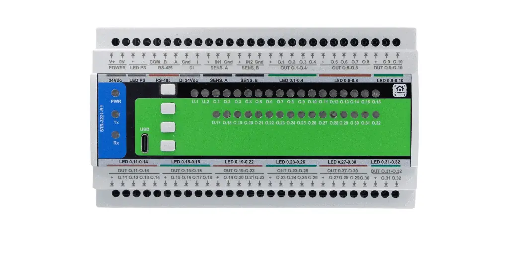
32 dimmable channels
Low-side MOSFET outputs for 12–24 V LED steps and valve heads, 1.5 A each — one channel per step.
Stairs run on the module
Direction, pattern and fade live in the module. The home server sets day and night levels; the run itself does not need it.
Underfloor heating zones
Slow PWM for thermal actuators, valve exercise and frost protection, with a heat-demand flag for the pump.
Open hardware
Schematics and PCB files under CERN-OHL-W v2, firmware under MIT. You own the design, not a vendor.
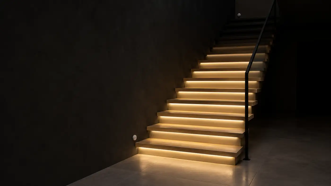
STR-3221-R1 · per-step stair lighting
Every step lights up in order. The module runs it.
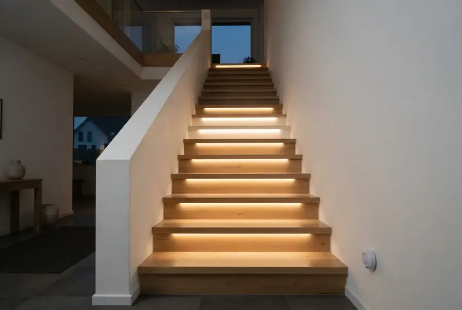
A presence sensor at each end, one channel per step, up to 32 steps. Direction, pattern and fade live in the module; Home Assistant sets the levels.
32-channel LED stair lighting controller for Home Assistant
Modbus RTU module · MiniPLC or MicroPLC · Home Assistant via ESPHome · 12–24 V DC loads
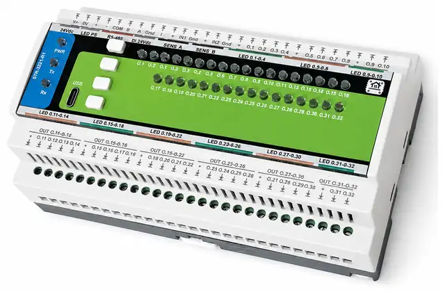
HomeMaster STR-3221-R1 is a DIN-rail output module with 32 dimmable low-side MOSFET channels for 12–24 V DC loads — one channel per stair step, per LED segment or per underfloor-heating valve head. It sits on the RS-485 bus of a MiniPLC or MicroPLC and appears in Home Assistant through the controller's ESPHome package: 32 dimmable lights plus stair and heating controls, with no Modbus register mapping.
Presence sensors at the bottom and the top start the stair run and set its direction; the module lights the steps one by one and fades them out. The same channels can drive underfloor-heating valve heads. Home Assistant sets day and night levels, scenes and zone setpoints.
Home Assistant is the main platform, not the only one: with MQTT enabled in ESPHome on the controller, the STR-3221-R1 also works with openHAB, ioBroker, Node-RED and SCADA systems — and any Modbus RTU master can drive it directly.
What you can build with the STR-3221-R1
One module, 32 channels, 12–24 V DC. Loads above 1.5 A per channel go through a relay or a contactor.
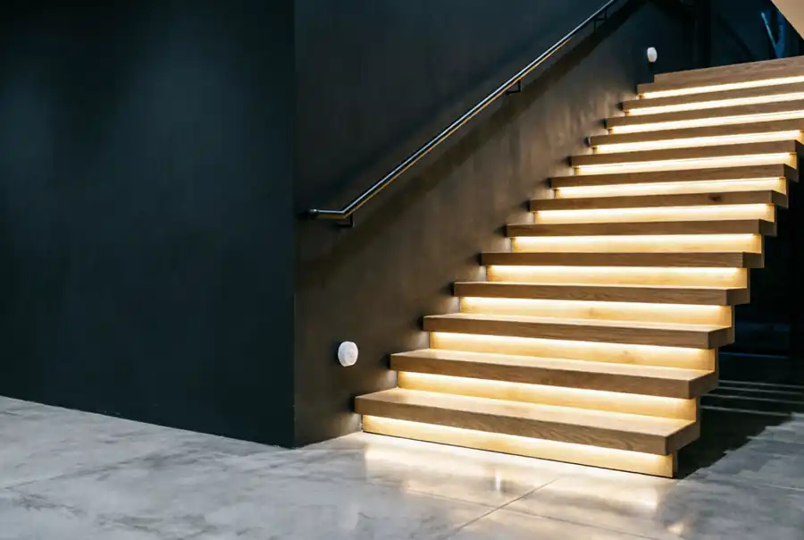
LED stair lighting per step
One channel per step, presence sensors at both ends. Up to 32 steps on one module. Full build →
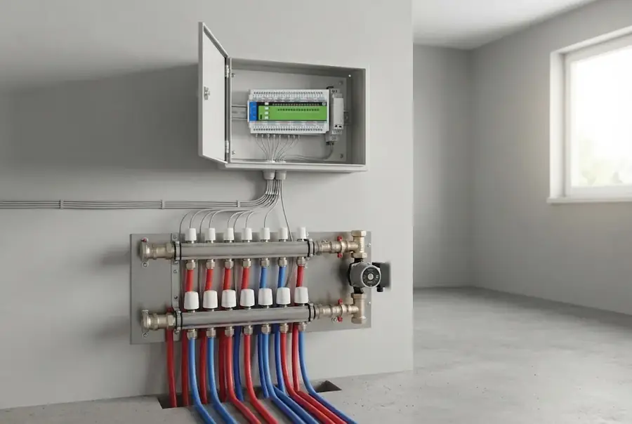
Underfloor heating zones
Up to 32 thermal actuators, slow PWM per zone, pump demand to the controller, valve exercise in summer.
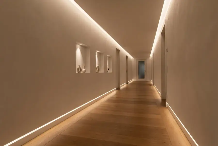
Corridors, coves and night light
Dimmable 12–24 V strips in coves, skirting and niches: groups, scenes and a night-light level from Home Assistant, local buttons for all on and all off.
Inputs and outputs at a glance
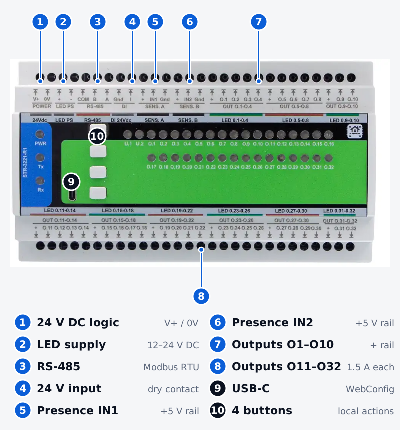
32 dimmable MOSFET outputs
Low-side switching for 12–24 V DC LED segments and valve heads, 1.5 A per channel. Linear, gamma or CIE curve, min / max and ramp per channel.
Presence inputs for stair sensors
IN1 and IN2 with their own fused 5 V rails for PIR or radar sensors at the bottom and the top of the stairs.
24 V digital input
Dry contact wetted by the module: a wall switch, a scene button, or enable / inhibit for the heating loop.
RS-485 Modbus RTU
Slave on the controller's bus, address 3 at 19200 baud out of the box. Any Modbus RTU master can drive it.
USB-C WebConfig
Set up channels, stairs and heating from a browser — no driver, no software to install. Settings are kept in flash.
Buttons and status LEDs
4 buttons with local actions (all on, all off, scene, panic) and 2 assignable status LEDs. Local actions take priority over the bus.
What problems it solves
No cloud, no manufacturer account
Nothing leaves your network. The module talks Modbus to your controller, and the controller talks to Home Assistant locally over the ESPHome API — no vendor cloud, no account, no subscription.
No vendor lock-in
Standard Modbus RTU with a published register map, open schematics and open firmware. You can repair it, reflash it or drive it from another master — the design is yours, not a vendor's.
No breadboard in a cupboard
Per-step stair lighting usually ends up as an ESP32 board, a PWM breakout and a MOSFET board wired by hand. This is one DIN-rail module with protected inputs and pluggable terminals, wired and signed off in a panel.
Any staircase, 2 to 32 steps
Free channel map, six patterns, day and night levels, and standby lighting whose first and last channels you pick in WebConfig, not written in code.
Stairs and heating run on the module, not on the home server
The stair run and the heating-zone cycle are executed by the module itself. The home server changes levels, windows and setpoints and shows the state.

Stair run
A presence sensor starts the run on the module: direction, pattern, hold and fade.
Night light
Standby on the first and last channels you choose — always, or only while the night window is on.
Valve heads
Slow PWM with phase spread and a cap on how many zones open at once.
Exercise and frost
Valves are exercised in summer; frost protection takes over after the silent hours.
Buttons and panic
4 local buttons act on the module directly and take priority over the bus.
Panic drives the lighting to the panic level and keeps every valve head closed.
Built for the cabinet, not the workbench
Hand-built LED controllers switch MOSFETs straight from a GPIO. The STR-3221-R1 is built with industrial-grade protection on every channel and every input, in a DIN-rail housing with pluggable 5.08 mm terminals.
None of the field interfaces is galvanically isolated: the module is for SELV wiring in one cabinet, with one 0 V reference.
CE-marked, EMC tested at an external laboratory.
Gate RC and ferrite
On every one of the 32 channels.
1.5 A per channel
18 A per module across nine output groups.
TVS on IN1 / IN2
Presence inputs clamped against surges.
Fused 5 V rails
Sensor supply fused, separate from the outputs.
PTC and TVS on 24 V in
The digital input is protected on both.
RS-485: 3× TVS, 2× PTC
A–COM, B–COM, A–B; 1.5 A PTC on A and B.
Common-mode choke
Plus fail-safe biasing on the bus.
Power input
1 A fuse, TVS, reverse-polarity protection, EMI filter.
Per-step stair lighting with presence sensors
Put one 12 or 24 V LED strip under each tread and a presence sensor at each end. The first sensor to fire sets the direction; the module lights the steps in order and fades them out after the hold time.
Six patterns — sequential, all, wave, comet, centre and random — with step delay, hold, fade and overlap. Day and night levels, standby lighting on channels you choose, and an inhibit from Home Assistant.
Home Assistant sets the night window and the levels. Per-step stair lighting guide →
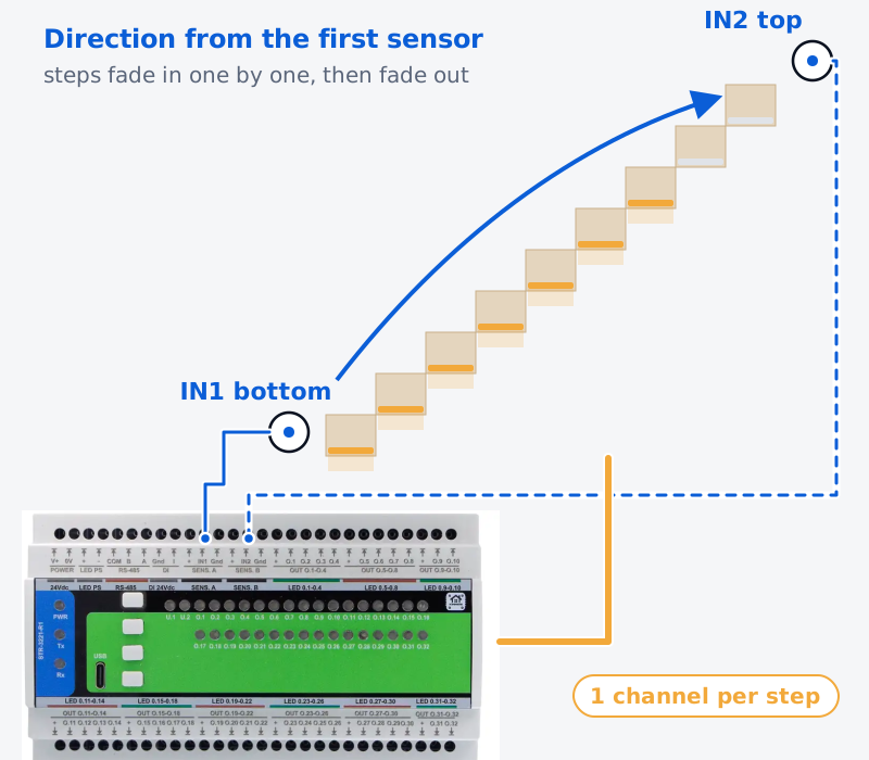
How a stair run works
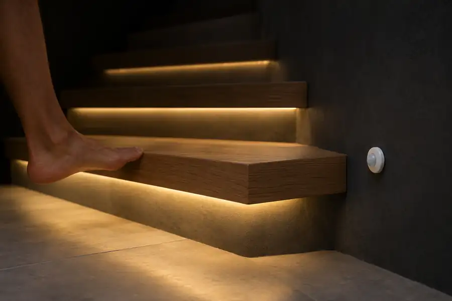
Presence at either end
The first sensor to fire sets the direction — up or down.
Steps light in order
One by one with the step delay, in the pattern you chose.
Hold
Steps stay on for the hold time, or while presence lasts.
Fade out
Then they fade back to off, or to the standby level on the first and last channels you chose.
Six patterns
Sequential
Steps light one by one in the direction of travel.
All
Every step lights at once.
Wave
A group of lit steps travels along the stairs.
Comet
A bright head with a fading tail runs ahead.
Centre
Light starts at the middle and spreads to both ends.
Random
Steps light in random order.
Day level, night level and night light
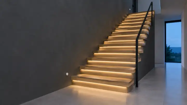
Day level
Steps run at full brightness while the house is awake.
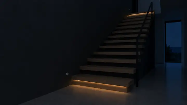
Night level and night light
Home Assistant switches the night window; the run dims and the first and last step keep a soft glow.
What you need for one staircase
| STR-3221-R1 | 1 module for up to 32 steps |
|---|---|
| Controller | MicroPLC for stairs and lighting, MiniPLC if heating is on the same bus |
| Presence sensors | 2 — bottom and top, PIR or radar, powered from the IN1 / IN2 5 V rails |
| LED strips | 12 or 24 V constant-voltage, one segment per step |
| Logic supply | 24 V DC DIN-rail supply; can also feed the controller |
| LED supply | 12–24 V DC DIN-rail supply, sized for the LED load |
Sizing the LED supply: an example
16 steps × 1 m of 24 V strip at 9.6 W/m = 154 W. Add 20 % reserve → 185 W, so a 24 V 200 W (8.3 A) supply.
Each step draws 0.4 A — well under 1.5 A per channel; the module carries 6.4 A of its 18 A.
Underfloor heating valve heads for Home Assistant
Any channel can run the Heat profile and drive a 24 V thermal actuator. The module runs slow PWM with phase spread, a cap on simultaneously open zones, valve exercise and frost protection, and raises a heat-demand flag for the pump.
The MicroPLC relay is C / NC only. For a pump or boiler demand that closes when energised, use a MiniPLC relay or a relay module.
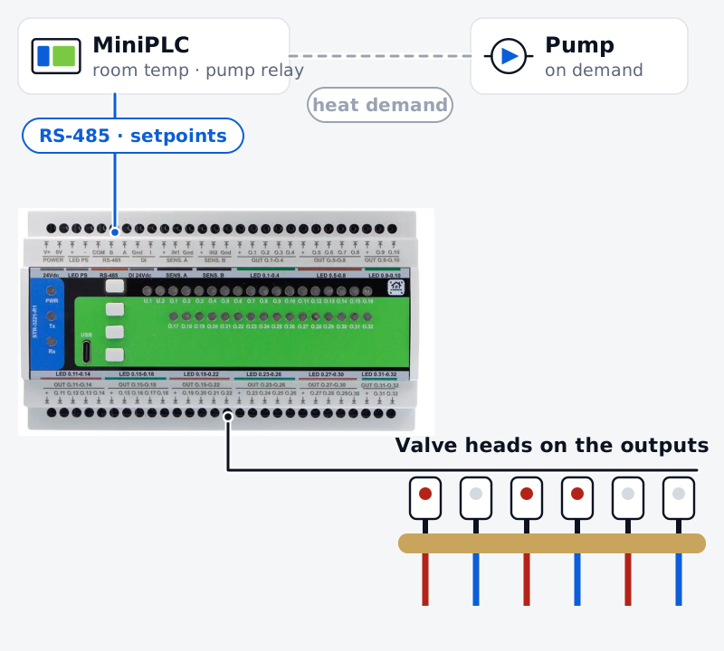
On the module
Valve heads with slow PWM, phase spread and a cap on open zones · enable / inhibit on the 24 V input · heat-demand flag with first-open delay · valve exercise and frost protection.
On the controller
Room and floor temperature · setpoints, schedule and the control loop · pump and boiler relays.
One module, light or heat
Each channel has its own profile — LED, Heat, Raw or Indicator — so stair steps, valve heads and cove strips can share one module.
32 stair steps
16 steps + 12 valve heads + 4 cove strips
32 valve heads
Which controller runs it
The STR-3221-R1 is a Modbus module: the controller brings it into Home Assistant.
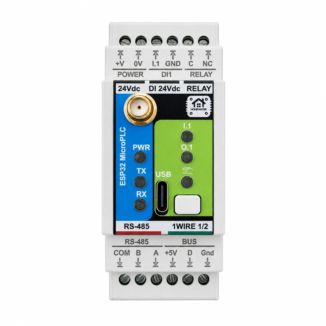
MicroPLC
For stair lighting and LED scenes
- Relays
- 1 × C / NC (fail-safe)
- Inputs
- 1 digital, 1-Wire
- Power
- 24 V DC
- Network
- Wi-Fi
- Width
- 2 DIN modules
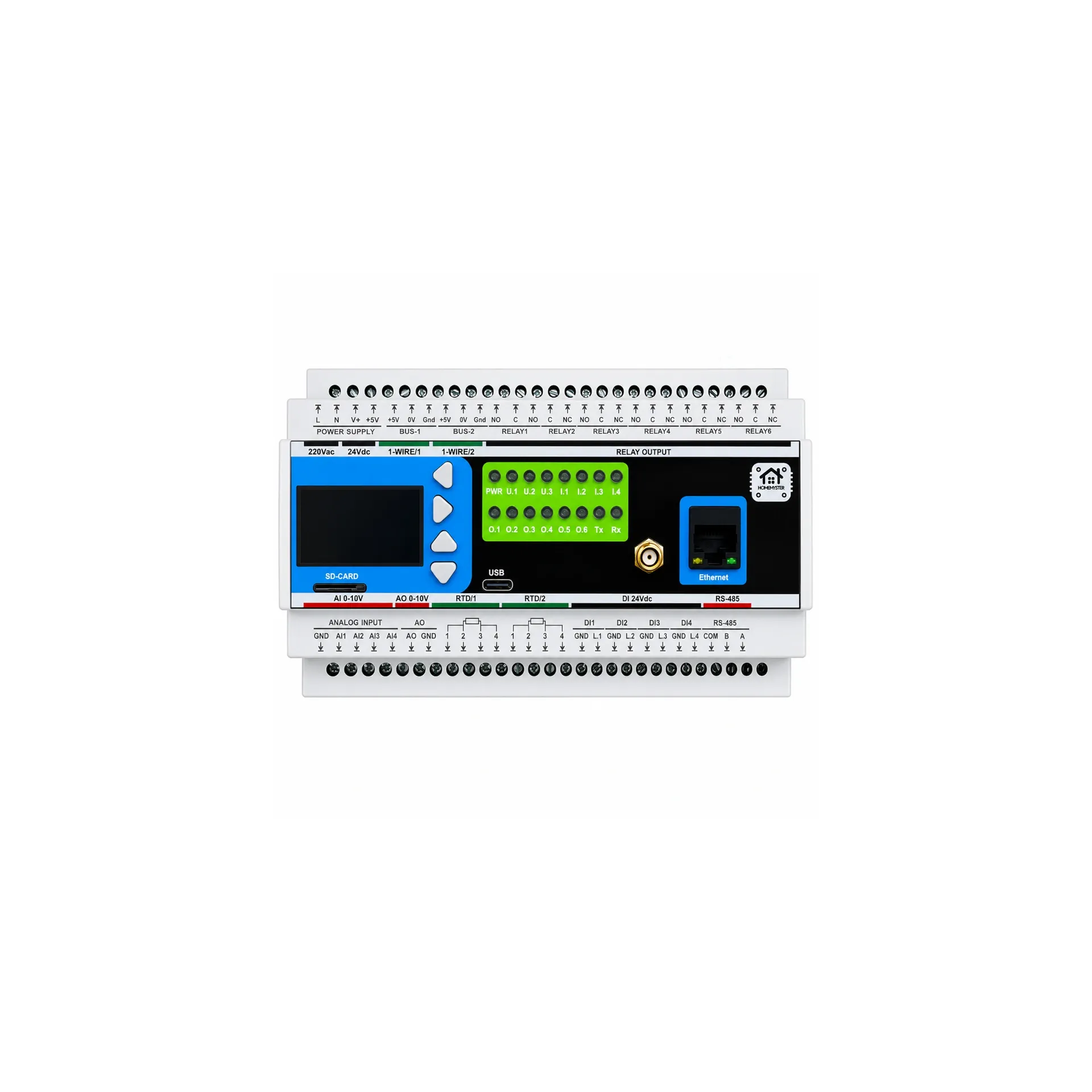
MiniPLC
For underfloor heating with pump and boiler relays
- Relays
- 6 × SPDT
- Inputs
- 4 digital, 2 × PT100/PT1000, 2 × 1-Wire, 4 × 0–10 V
- Power
- 24 V DC or 85–265 V AC
- Network
- Wi-Fi or Ethernet
- Width
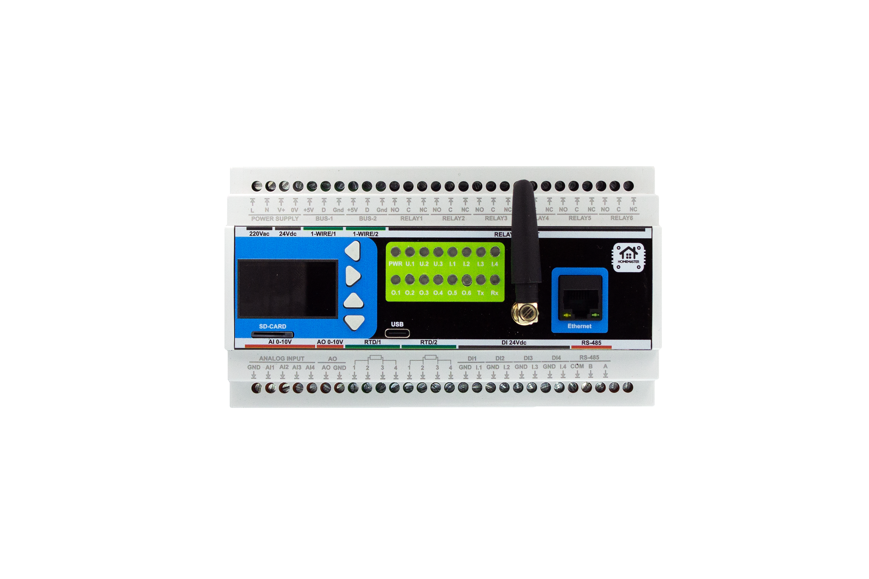
- 9 DIN modules
Stairs and lighting only — a MicroPLC is enough. Underfloor heating with pump and boiler relays and room sensors — use a MiniPLC. Both run the same ESPHome package; plan the panel in the System Builder.
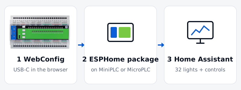
Set up in three steps — no code
Connect USB-C and open WebConfig in the browser: set the Modbus address, choose the profile of each channel (LED, Heat, Raw, Indicator) and fill in the stair or heating card.
Add the STR package to the ESPHome configuration of your MiniPLC or MicroPLC with that address. After the controller restarts, 32 lights and the stair and heating controls appear in Home Assistant.
Factory address is 3 at 19200 baud — give each module on the bus its own address.
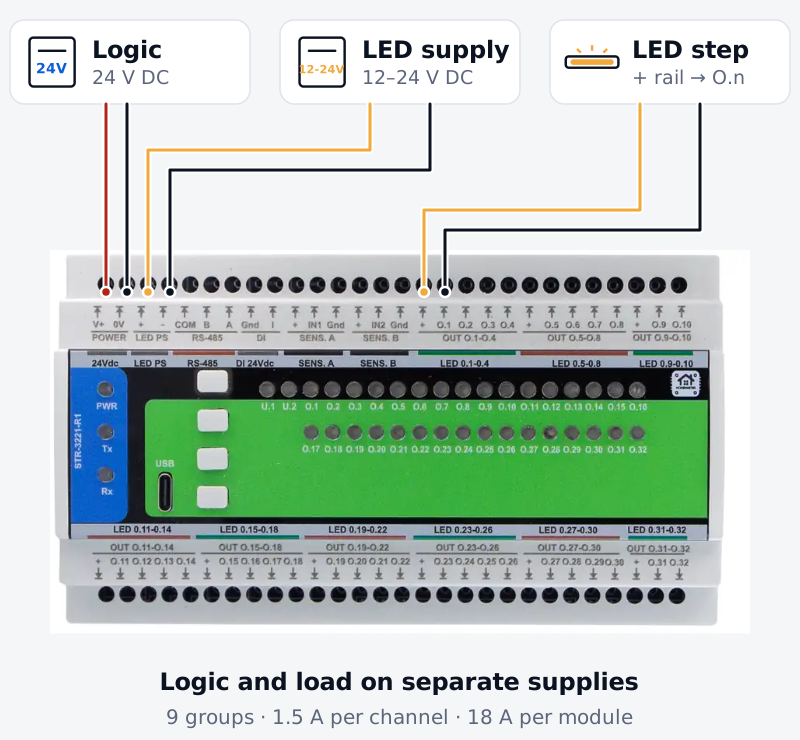
Power: 24 V DC logic, 12–24 V DC for the loads
The module needs two supplies. 24 V DC on V+ / 0V runs the electronics (0.2–0.5 W). A separate 12 or 24 V DC supply on LED PS feeds the nine output groups; size it for the total LED or actuator load, up to 18 A per module.
Each group has its own + rail: the load + goes to the group rail, the load − to the channel terminal.
The 5 V sensor rails are for presence sensors only, never for LED segments.
Technical specifications
| Microcontroller | RP2350A, dual-core |
|---|---|
| Outputs | 32 × low-side MOSFET, PWM dimmable, 1.5 A per channel, 18 A per module |
| Output groups | 9 groups, each with its own + rail |
| Load supply | External 12–24 V DC on LED PS, separate from the logic supply |
| Logic supply | 24 V DC, typical 0.2–0.5 W |
| Presence inputs | 2 × IN1 / IN2 with fused 5 V sensor rails |
| Digital input | 1 × 24 V, dry contact, wetted by the module |
| RS-485 | Modbus RTU slave, half-duplex, surge-protected, not galvanically isolated; address 3, 19200 baud, 8N1 |
| Configuration | WebConfig over USB-C in the browser; settings stored in flash |
| Controls | 4 buttons, 2 status LEDs, 32 channel indicators |
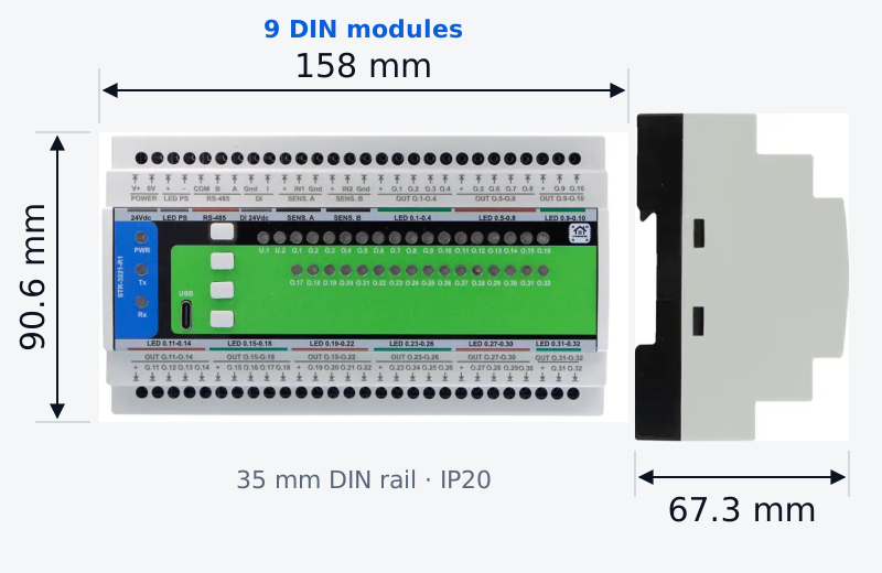
| Dimensions | 158 × 90.6 × 67.3 mm, 9 DIN modules, 35 mm rail |
| Terminals | Pluggable screw terminals, 5.08 mm, 0.2–2.5 mm² |
| Environment | 0 … +40 °C, 0–90 % RH non-condensing, IP20, indoor control cabinet |
| Weight | 150 g |
| Warranty | 24 months |
Datasheet DS-STR-3221-R1 Rev. B · 2026-09 · Hardware R1 (V1.0) · Firmware v0.4.0
What it is not
- Not a thermostat: it does not measure temperature or run a control loop — the controller does.
- Not stand-alone in Home Assistant: it needs a Modbus RTU master such as a MiniPLC or MicroPLC.
- 12–24 V DC loads only — no 230 V lamps or 230 V valve heads.
- Not for addressable pixel strips: one PWM channel per constant-voltage segment.
- No galvanic isolation on any field interface — SELV wiring, one 0 V reference, an isolator where the bus leaves the installation.
- 1.5 A per channel, 18 A per module — heavier loads through a relay or a contactor.
Documents and downloads
| Datasheet | STR-3221-R1_Datasheet.pdf |
|---|---|
| EU Declaration of Conformity | DoC_STR-3221-R1.pdf |
| ESPHome package | default_str_3221_r1_plc.yaml |
| WebConfig | Open WebConfig |
| Schematics | Schematics/ |
| Full technical reference | README.md |
Wiring and installation
The terminal map, wiring steps, power notes, WebConfig reference, Modbus register map and Home Assistant entities are in the technical README:
Build guides
CE: EMC 2014/30/EU (EN 55032 Class B, EN 55035, tested at Idvorsky Laboratories), RoHS 2011/65/EU. SELV product, 24 V DC. HomeMaster® is a registered EU trademark (EUTM 019082911). Hardware under CERN-OHL-W v2, firmware under MIT.
Related products
These other products might interest you