Building a Wired Water-Leak Shut-Off That Closes the Valve on Its Own
A leak system is only worth having if it can still close the valve when something else has failed. That means putting one small decision — water detected, shut the water off — somewhere that does not depend on a battery, a radio link, a network or a server. On a DIN rail, that place is the module itself.
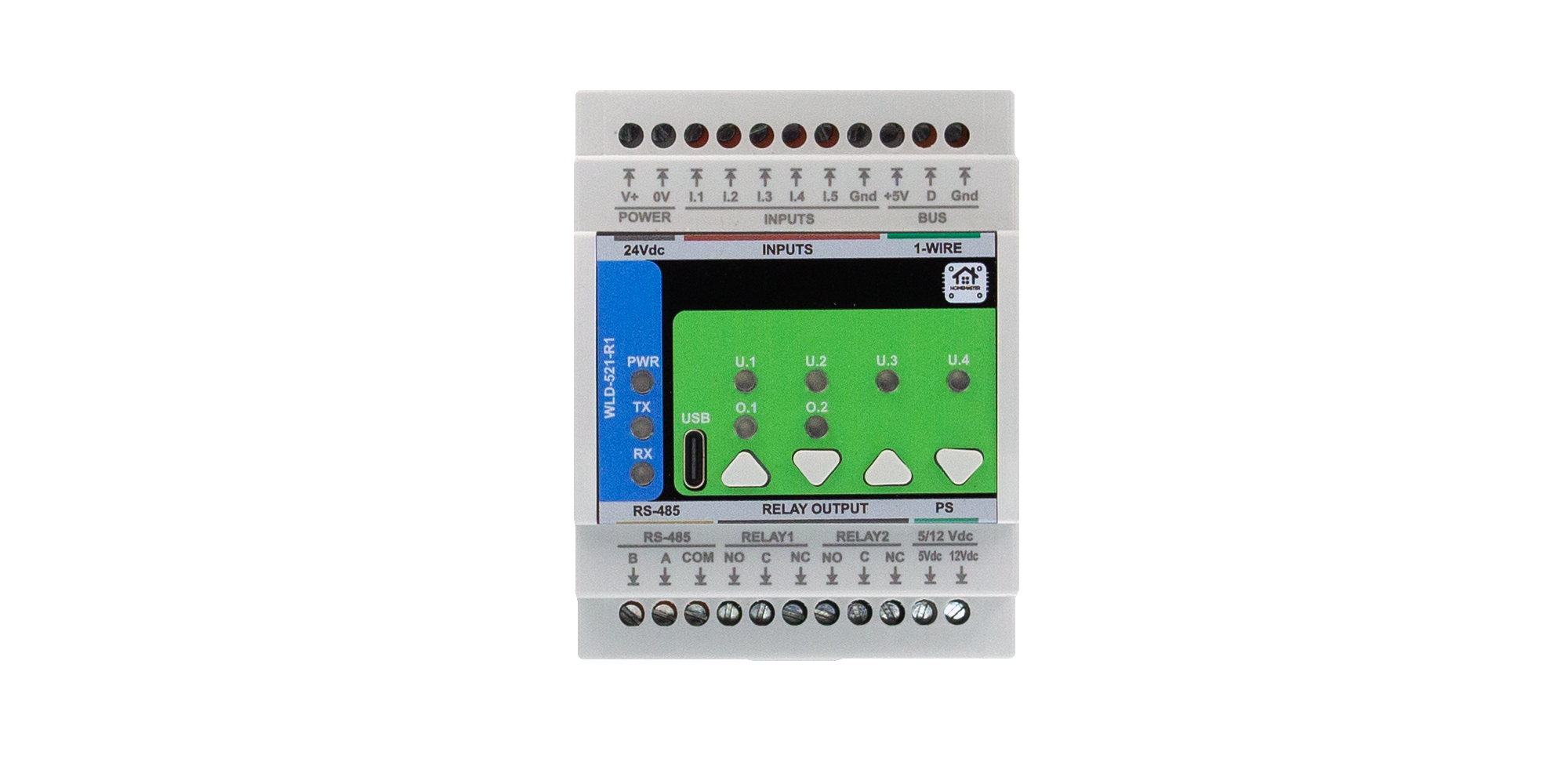
The short version. A leak sensor wired to a WLD-521-R1 can drive a relay directly, because the rule connecting the two is stored in the module's own flash and executed by its own processor. Home Assistant still sees everything and still does the notifications, history and wider automation — it just is not standing between the puddle and the valve. What this does not survive is losing power, and the article says so plainly. It also says what a wired input does and does not tell you about a cut cable.
1. Two Leaks, and the Difference That Matters
Two houses, same failure.
In the first, a sensor detects water and the valve closes. The result is a wet floor and a story to tell.
In the second, a battery-powered sensor had been sitting there for two years. Its battery died three months before the leak. Nobody noticed, because a dashboard with no alarm on it looks exactly like a dashboard with nothing wrong.
That is the distinction worth holding onto, and it is not about radio. Wireless leak sensors detect water perfectly well; plenty of basements have been saved by one. The problem is silent failure — a flat battery, a lost radio link or a device that has quietly dropped off all produce the same thing: no event. On a screen, "nothing happened because everything is fine" and "nothing happened because the sensor is dead" are the same picture.
None of which means ripping out wireless sensors. It means putting wired ones where water gets expensive fastest:
- the main water entry and the meter cupboard
- manifolds and collectors
- the boiler or water heater
- behind the washing machine and the dishwasher
- any low point where water collects before anyone sees it
2. Where the Chain Normally Breaks
A server-dependent leak automation looks like this:
sensor → radio → network → server → automation → relay → valve actuator
Every one of those has to be working at the same moment: the sensor, its battery, the radio link, the router, the server, the automation you wrote, and the actuator. For switching on a lamp at sunset, that is a perfectly reasonable chain. For the one action whose whole purpose is to work on the worst day of the year, it is worth asking how many of those links really need to be in it.
With the rule stored on the module, the chain is:
sensor → module input → rule in the module → relay → valve actuator
The decision is made by the module. The controller on the RS-485 bus does not have to be alive for this particular action, and neither does the server.
The limitation, stated before anyone gets comfortable. None of this works during a power failure. The module needs its 24 V supply and the valve actuator needs its own. "Keeps working when the server is down" and "keeps working when the electricity is off" are two different claims, and mixing them up is how people end up disappointed at exactly the wrong moment. If continuity through an outage matters, that is a UPS on the automation supply and a deliberate choice of actuator — a separate design decision, not a side effect of this one.
3. Connecting the Sensors
The module takes both kinds of leak detector: passive ones that just close a contact when wet, and powered ones that need a supply of their own. It has isolated 5 V and 12 V rails on the terminal block for the second kind, so a detector does not need its own adapter. Those rails share a sensor budget of roughly 150 mA between them, which is generous for a handful of leak probes and tight for a dozen active detectors — worth checking against your detectors before you commit to a layout. The rails are isolated from the logic side, and the return for the inputs is the separate GND_ISO terminal, not the module's 0 V.
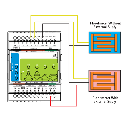
Placement decides whether it works. A contact detector senses water bridging its electrodes, which means it has to sit at the lowest point of the area it protects, not beside the pipe at a convenient height. Water finds the floor long before it finds the sensor you mounted on the wall. The cable to it is ordinary low-voltage signal wiring and can be run with the rest of the building's low-voltage cable.
What a wired input does not tell you. A wired detector is read continuously, so there is no question of a message that never arrived — but be precise about what that buys. These inputs are plain contact inputs without end-of-line supervision: there is no terminating resistor and no way for the module to tell "the loop is intact and dry" from "somebody cut the cable". A severed detector cable reads as no water. That is the honest limit, and it has a practical consequence: the twice-a-year test in section 8 is not optional decoration, it is how a dead detector gets found.
False alarms are a placement problem too. A contact sensor has no opinion about why the floor is wet. A leak and a freshly mopped floor produce the same electrical state. That is a reason to think about where the detector sits, and a reason the input has an invert option so that the normal and alarm states match how the detector is built.
4. The Rule Lives in the Module
This is the part that makes the whole thing work, and it is three dropdowns.
The module has five digital inputs. They are identical and universal — each one is whatever you configure it to be — and each is set up with three fields:
- Type — what is connected: a water sensor, a humidity sensor, or a water counter.
- Action — what happens when it activates.
- Control target — which relay it acts on: one specific relay, or all of them.
So "this detector closes that valve" is not an automation written on a server. It is a row of settings stored in the module's flash and evaluated by the module's own processor, every cycle, whether or not anything is polling the bus.
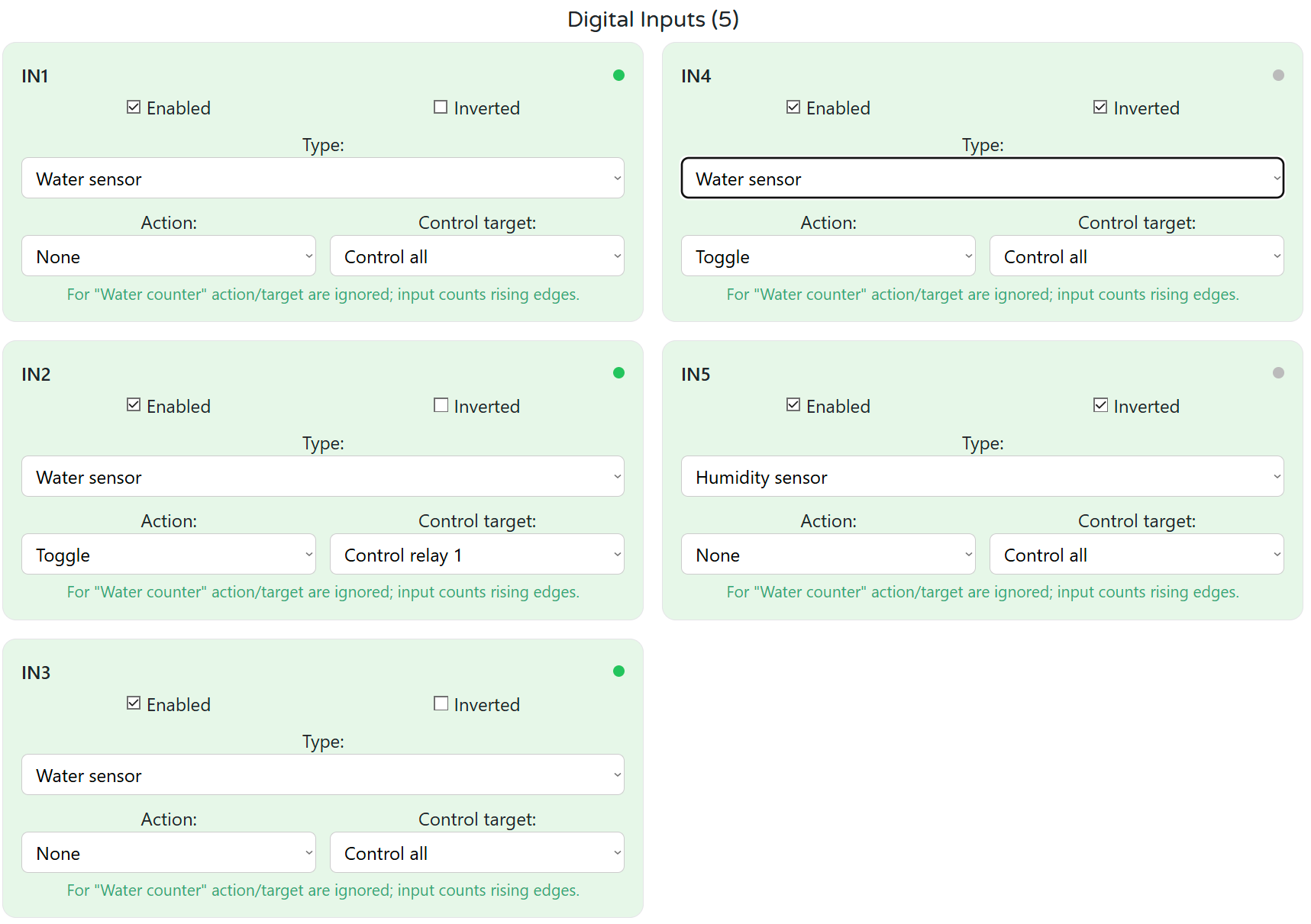
One line of the interface is worth quoting because it explains the model better than a paragraph would: for the water counter type, the action and target fields are ignored and the input simply counts rising edges. An input is either part of the local decision or it is a meter — never quietly both.
Configuration is done in a browser over USB-C and stored on the device. It survives a power cycle, and it does not depend on the controller being present — or, for that matter, on the controller ever having existed.
5. The Relay Drives the Actuator — It Is Not the Valve
We do not make a valve. The actuator is somebody else's device, and how it wires up depends entirely on which kind you bought.
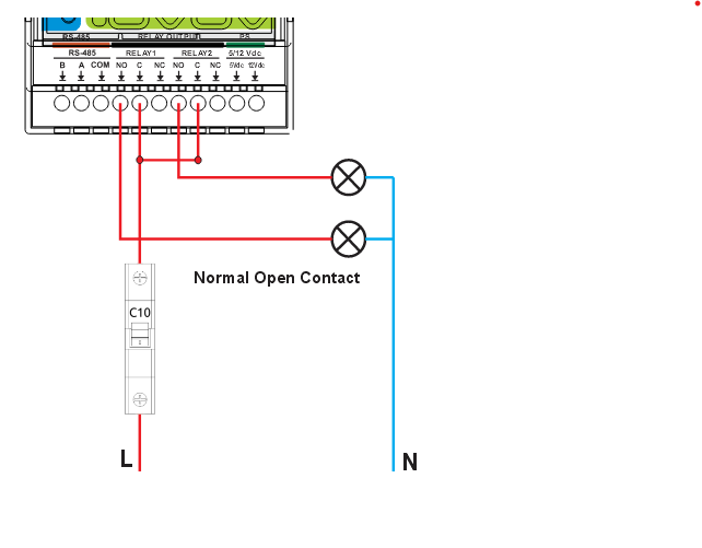
The module gives you two SPDT dry-contact relays — COM, NO and NC on each, so a circuit can be made or broken depending on which pair you land on. They are rated 3 A at 250 V AC, with a ceiling of 750 VA at 250 V AC or 90 W at 30 V DC. The relay component fitted is rated higher than that on its own datasheet, but that number belongs to the component, not to the module: terminals, board and compliance set the limit at 3 A. There is also no fuse inside — overcurrent protection is the panel's job, and anything inductive, a pump or a large solenoid, wants a snubber and probably an external contactor.
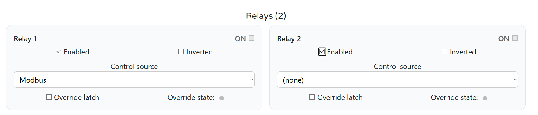
Check who owns the relay. Each relay has a control source setting that decides whether it follows the module's own logic or the bus. For leak protection it has to be the module's logic — this is the one setting in the whole installation that is worth opening and looking at rather than assuming, because it is the difference between a valve that closes on its own and a valve that waits politely for a master that is not there.
Actuators differ, and it matters. A motorised ball valve with two control wires and internal limit switches is wired one way; a three-wire actuator another. A solenoid is a different animal again: it holds its position only while energised, so on losing power it springs back to whichever state it was built for. Whether that is a happy ending or a flood depends entirely on whether you fitted a normally-open or a normally-closed one, and that is a decision to make deliberately rather than discover.
The actuator is powered from its own supply, not from the module. The module switches it; it does not feed it.
One more thing that belongs here rather than in the small print: after power is restored, relays come up according to their configured power-on state, not according to what they were doing before the cut. It is a per-relay setting, and for a valve it is worth choosing on purpose.
6. Five Inputs Do More Than Find Puddles
Five inputs for two detectors sounds like too many until you notice they are not dedicated. They are identical and each one's job is chosen in configuration, so one module can carry the whole water story for a house.
Humidity, for the warning before the puddle. In a cellar, a crawl space, a service void or under a piece of equipment, the useful early signal is not "there is standing water" but "it is getting damp in here". A leak detector answers the first question. A humidity sensor on another input answers the second, days earlier.
A pulse-output water meter, as a counter. Set an input to the water counter type and it counts pulses instead of triggering a relay.
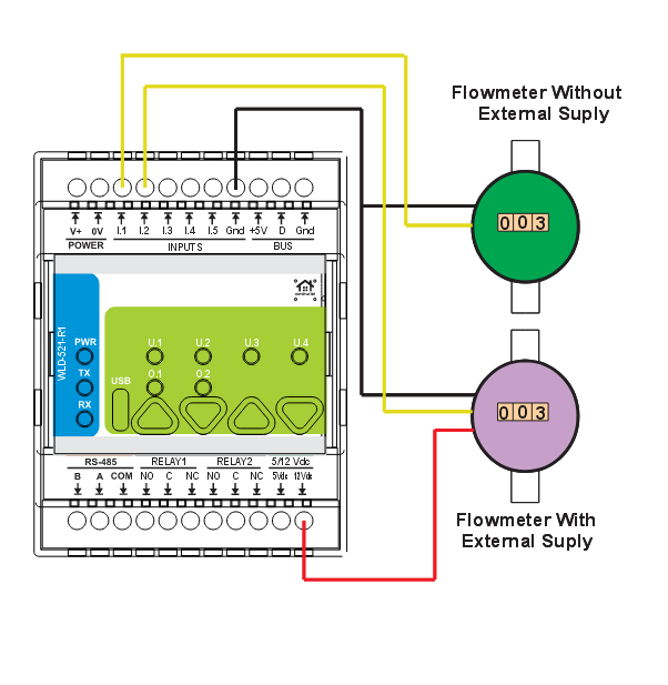
Be clear about what a pulse count is: accumulated volume. Instantaneous flow is inferred from how fast the pulses arrive, so how good that number is depends on the meter's pulse resolution, not on the module. A meter that emits one pulse per litre tells you very little about a slow drip. The counting input handles roughly nine or ten pulses per second in practice, which is comfortably more than a domestic meter produces.
7. Temperature over 1-Wire, and an Honest Word About Heat
The module has a 1-Wire input. Sensors on it are discovered by the module, given names, stored in flash and shown in the browser with live readings before any integration exists — which also makes it a quick way to check the wiring before wiring anything into Home Assistant.
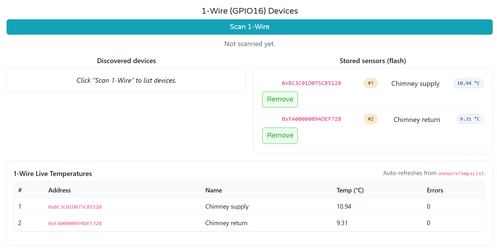
Put temperature on the flow and return of a circuit, add volume from the counter, and you can estimate how much heat went where. Now the caveat that has to be in the same breath, not three paragraphs later: this is indicative monitoring, not metering. There is no metrological approval and no MID certification. It is good for spotting a trend, catching an anomaly and arguing with yourself. It is not good for billing, for splitting costs between apartments, or for arguing with a utility — and anyone who tells you otherwise is selling something.
8. Test the Whole Chain Twice a Year
A shut-off system is not reliable because the dashboard is green. It is reliable because somebody checked.
A valve that has not moved in two years may not move when asked. A detector may be under a layer of building dust. A configuration may have been changed during unrelated maintenance and never changed back. So, twice a year, in daylight, with nobody depending on the outcome:
| Step | What to do | What you are actually testing |
|---|---|---|
| 1 | Wet each detector with a damp cloth | The detector and its cable are alive |
| 2 | Watch the input change in the browser or in Home Assistant | The input sees it |
| 3 | Listen for the relay | The rule fired |
| 4 | Check the water actually stopped, at a tap | The actuator moved — the step people skip |
| 5 | Repeat with the controller powered down | The rule really is on the module |
| 6 | Repeat with the server shut down | Nothing quietly depends on Home Assistant |
| 7 | Write down what happened | Next year's you |
Step 4 is the one that gets left out and the one that fails. A relay that clicks is not water that stopped.
Step 5 is the one that tells you the truth about your configuration. If the valve stops closing when the controller is off, the rule was never local — and now you know, on a dry afternoon instead of at two in the morning.
Re-run the test after rewiring, after reconfiguring the module, and after a firmware update.
9. Bringing It Into Home Assistant
The module sits on the RS-485 bus as a Modbus slave. The master is a MiniPLC or a MicroPLC running ESPHome, and from there it reaches Home Assistant over the native API — no broker, no register map to maintain by hand.
What arrives on the bus is concrete: the state of all five inputs, the state of both relays, and per input a flow rate and an accumulated volume. Where 1-Wire probes are fitted, their temperatures come across too, and from volume and temperature the module also publishes derived heat figures. All of it is sent as scaled integers — volumes and rates multiplied by a thousand — so a value that looks absurd is usually a missing division rather than a broken sensor. Out of the box the module answers on address 3 at 19200 baud, and both are changed in the same browser interface as everything else.
What that gives you is two layers doing different jobs. The local layer is detector to module to relay to actuator, and it is what stops the water. The supervisory layer is module to bus to controller to Home Assistant, and it is what tells you it happened, keeps the history, and lets a leak in the cellar also switch something off upstairs. Which rules belong at which level is the subject of its own article: what still works when Home Assistant is down.
One wiring detail that costs people an evening. The RS-485 terminal order on this module is B, A, COM, and it is not the same order used on every other module in the range. Swapped A and B is the single most common reason a bus refuses to come up. Look at the silkscreen, not at the module next to it.
10. What This Is Not
Not a certified flood-protection system. There is no functional-safety rating and no redundant path. It is a sensor, a rule and a relay, arranged so the rule does not need permission from anything else.
Not the valve. The actuator is external, and the reliability of the installation includes it.
Not a certified meter, for water or for heat. Useful for monitoring and anomalies, useless for billing.
Not a substitute for building sense. A water heater still wants a drip tray and a drain. Local logic does not replace a floor that slopes the right way.
Not supervised wiring. No end-of-line resistor, no cut-cable detection. Section 3 explains what that means and section 8 is the answer to it.
No fuse in the relay. Circuit protection is the panel's job, as it is for anything else on the rail.
RS-485 is not galvanically isolated. There is transient protection, which is not the same thing. Where the bus crosses into a separate electrical installation, fit an external isolator at that boundary.
11. The Takeaway
The interesting thing about this installation is not the input count, the bus, or even Home Assistant. It is where one decision is made.
A server-dependent system has to ask: did the sensor report, did the radio deliver, did the network carry it, did the server process it, did the automation fire, did the command arrive? A local one asks a single question: did the input go active? If yes, the relay moves.
Everything else — the notification on your phone, the history, the graph that shows the meter ticking when the house is empty, the rule that also kills the pump upstairs — stays exactly where it belongs, in Home Assistant. It is only the emergency action that gets moved down, because it is the one that cannot afford to wait.
If you are planning the wiring around this, the companion pieces are connecting dozens of wired sensors without a wall of boards and, for how the layers fit together, the platform overview. To work out how many modules a panel actually needs, use the System Builder.