Monitoring More Circuits Than Your Panel Has Room For
A single meter on the incomer tells you that the house used electricity, which you already knew. Per-circuit metering tells you which circuit, when, and whether it is behaving — and the design question is never how to measure everything, it is which few circuits are worth a current transformer. Plus the one specification that will physically destroy the module if you get it wrong.
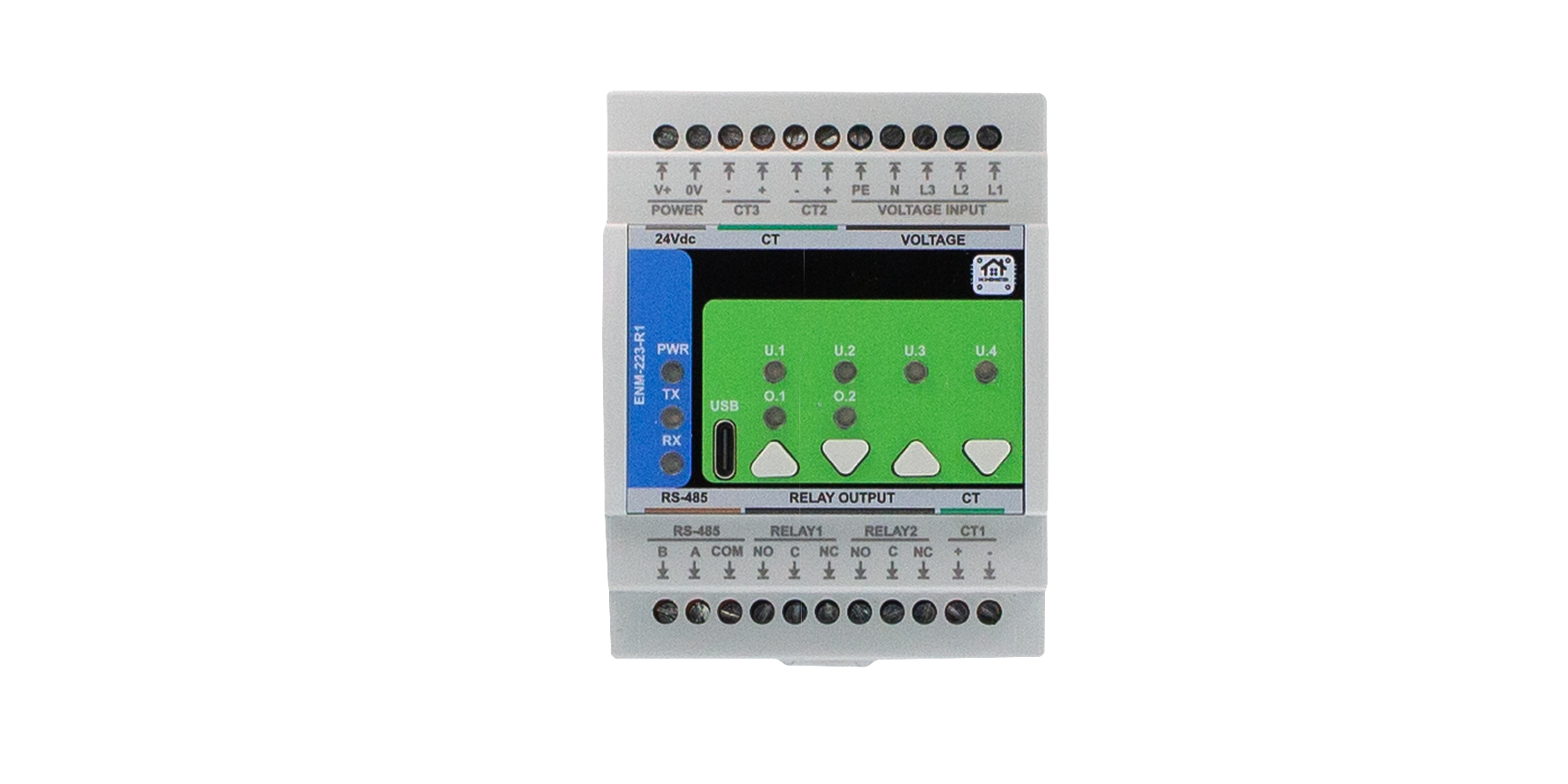
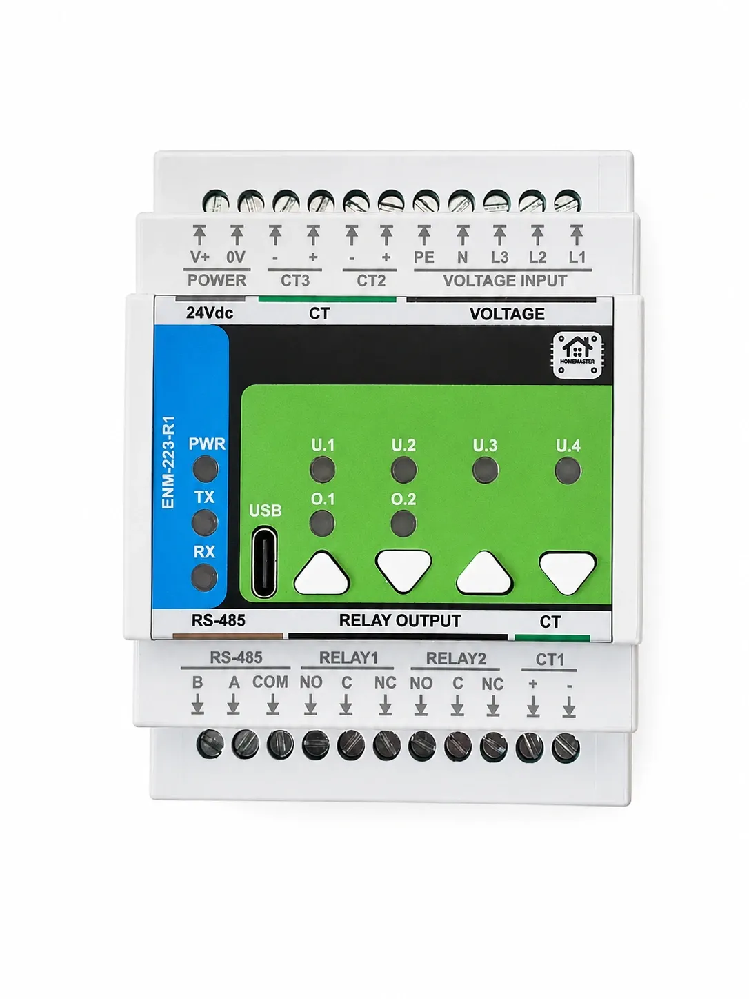
The short version. The ENM-223-R1 measures three current channels against three-phase voltage sensing, using an ATM90E32AS metering front end, and reports voltage, current, real, reactive and apparent power, power factor, frequency, phase angle, power-quality events and directional energy counters over Modbus. It needs current-output split-core CTs with a secondary of 60 mA RMS or less — a 1 A or 5 A CT will destroy it. It has no declared accuracy class and no MID approval, so it is an instrument for seeing what your installation is doing, not for billing anyone. And it can act on what it measures by itself, without a server.
1. One Meter Tells You Almost Nothing
Most homes that "have energy monitoring" have one clamp on the incomer. It produces a single number, and that number can only ever answer one question: how much is the house drawing right now.
Which is the question you least need answered. You already know the total at the end of the month, from the utility, with more accuracy than any clamp will give you. What a single figure cannot tell you is anything actionable:
- Which circuit is responsible for the overnight baseline that never goes away
- Whether the heat pump is drawing what it should, or slowly drawing more than it used to
- What the car charger is actually pulling when the oven is also on, and whether that combination is close to the main breaker
- Whether the immersion heater is running when nobody asked it to
Each of those is a per-circuit question, and none of them can be extracted from a total, no matter how clever the software. The interesting information is in the split.
2. What the Module Actually Measures
Worth being specific, because "energy monitoring" covers everything from a rough estimate to a metering-grade instrument, and the difference is in the list.
Read directly from the metering front end, per phase and as a total:
- Voltage — RMS on each of L1, L2 and L3
- Current — RMS on each of the three CT channels, plus a calculated neutral current
- Real power in watts, signed — so import and export are distinguishable
- Reactive power in var and apparent power in VA, both signed
- Power factor per phase and total, and phase angle
- Line frequency
- Total harmonic distortion of active power, per phase
- Power-quality events — sag, overvoltage, phase loss, overcurrent, frequency deviation and reverse phase sequence, as status bits
Accumulated by the firmware from the front end's counters, scaled to the primary side by the CT ratio:
- Active energy, import and export, per phase and total
- Reactive energy, import and export, per phase and total
The signed quantities are worth pausing on. A signed real power figure is what makes a solar installation legible: export shows up as negative, and the energy counters split cleanly into what you drew and what you sent back. An unsigned monitor simply cannot answer that question.
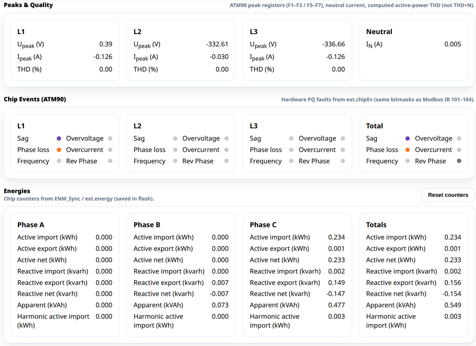
A handful of quantities — voltage and current peaks, fundamental and harmonic power, apparent energy — are shown in the module's own interface but are not published on the bus. If you need them in Home Assistant rather than on a screen during commissioning, that is worth knowing before you plan a dashboard around them.
3. The Specification That Destroys Modules
This is the section to read twice, because getting it wrong is not a configuration mistake — it is a purchase that ends with a dead module.
The module needs current-output CTs with a secondary of 60 mA RMS or less. The inputs are differential, terminated into a 6 Ω burden on the field board, with a full scale of 120, 60 or 30 mA depending on the gain setting — 60 mA at the factory default.
Do not connect a 1 A or 5 A secondary CT. Those are the standard industrial ratings, they are what a search for "current transformer" will mostly return, and they will put roughly twenty to eighty times the intended current into a 6 Ω burden. The documentation says it plainly: a 1 A or 5 A CT will destroy the module.
Two related habits from the same family of mistakes:
Never open a live CT secondary. A current transformer with its secondary open-circuited while primary current flows develops a dangerous voltage across the terminals. Short the secondary before disconnecting anything, always, on any CT, regardless of what it is connected to.
Watch out for voltage-output CTs too. Split-core sensors with a 333 mV output are common and are not the same thing as a current-output CT. They are the right answer for some meters and the wrong answer for this one.
4. Telling It What Your CTs Are
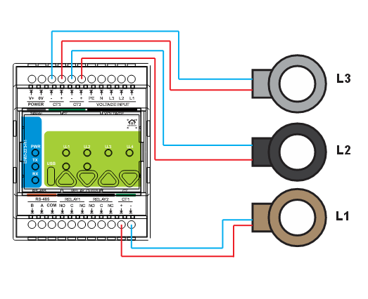
A CT is a ratio, and the module has to be told which one, because everything downstream — current, power, energy — is that ratio applied to what the front end actually measured.
Two numbers go into the configuration: the primary rating in amps, which is the current the CT is designed to measure, and the secondary in milliamps, which is what it produces at that current. The factory default is 100 A primary to 50 mA secondary. The primary can be set anywhere from 1 A up to 10 000 A; the secondary is clamped at 60 mA, in the firmware and in the interface, for the reason in the previous section.
Two practical consequences. First, oversizing the CT costs resolution — a 200 A CT on a 16 A circuit spends most of its range on current that will never flow, and the small readings get noisy. Match the CT to the circuit, not to the incomer. Second, the same physical CT on two different circuits needs the same ratio entered on both, so keeping a note of which CT went where saves a puzzled afternoon later.
5. Voltage Sensing: Three Phases or One
Current alone gives you amps. Power needs voltage as well, measured at the same instant and referenced to the same phase — which is why the module has voltage sensing terminals for L1, L2, L3, neutral and protective earth, and why those have to be connected for the power and energy figures to mean anything.
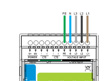
The module handles both a four-wire star arrangement with neutral and a three-wire arrangement without, selectable in the configuration, and the mapping of which CT belongs to which phase is set there too. That last point is not cosmetic: a CT clamped on L2 while the module thinks it is on L1 produces power figures that look plausible and are wrong, because the current is being multiplied by the wrong voltage waveform.
On a single-phase installation the same module still works — one CT, one phase connected — and the two unused channels simply read zero. Which is a reasonable way to buy: the module does not become obsolete if the house is later converted to three phase.
6. Three Channels, So Choose Your Three
Here is the constraint that shapes the design. Each module carries three current channels. Three-phase whole-house measurement uses all three, and then there is nothing left for individual circuits. Measuring individual circuits on a single-phase supply gives you three of them per module.
So the question is not "how do I measure everything", it is "which three". A workable priority order for a house:
| Priority | What to clamp | What it answers |
|---|---|---|
| 1 | The incomer | Total draw, headroom against the main breaker, export if there is solar |
| 2 | The largest single consumer — heat pump, boiler, car charger | Most of the bill, and the first thing to change behaviour when it degrades |
| 3 | The second largest, or a circuit you suspect | The mystery baseline, usually |
| later | Everything else | Diminishing returns — most circuits are noise |
The honest version of the trade-off: a second module triples the channels and costs another module. Whether that is worth it depends entirely on whether you will act on the extra data, and the answer for most houses after the first three circuits is no.
To turn a circuit list into a module count and see how the panel fills up, the System Builder does the arithmetic.
7. Measuring Is Half of It — Acting Is the Other Half
A number on a dashboard changes nothing. What makes metering useful is a rule attached to it, and on this module that rule can live on the device.
The two relay outputs can be set to alarm controlled instead of bus controlled: bound to a phase and to a condition — alarm, warning or event — with the thresholds evaluated by the module itself. When a relay is in that mode the bus does not write to it at all.
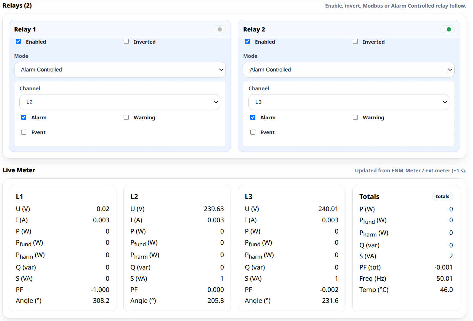
The classic use is load shedding: when total current approaches the limit of the main breaker, drop the least important large load — the immersion heater, the car charger — before the breaker does it for you and takes the whole house with it. That reaction has to be quick and it has to be reliable, which is exactly the kind of rule that does not belong on a server. Where each kind of rule belongs is the subject of what still works when Home Assistant is down.
The relays themselves are ordinary changeover contacts with the usual limits — 3 A at 250 V AC, no internal fuse — so a real load gets shed through a contactor. That whole subject is covered in how many relay channels you need and what should switch the load.
8. What It Is Not: No Class, No MID
This section is short and it is the one that keeps everybody honest.
There is no declared accuracy class. Not Class 1, not 0.5S, not Class B or C. The module does not carry one, and we are not going to imply one by quoting the front-end chip's capabilities as though they were the finished device's — the chip is one component in a chain that also includes your CTs, your clamp positions and your ratio settings, and the weakest of those sets the result.
There is no MID approval. The declaration of conformity covers EMC, low voltage and RoHS. It does not cover the Measuring Instruments Directive, and it is not going to.
What follows from that is practical: these figures are for understanding your installation, spotting anomalies and driving automation. They are not for billing a tenant, splitting costs between apartments, or arguing with a utility. Anyone doing those things needs a certified meter, and no amount of calibration in a web interface changes that.
Also worth saying plainly: accuracy is dominated by the CTs and the installation, not by the module. A cheap clamp that does not close cleanly around the conductor, or one sitting where two cables run together, will produce a wrong answer that the module will faithfully report to three decimal places.
9. Getting It Into Home Assistant
The module is a Modbus RTU slave on the RS-485 bus; a MiniPLC or MicroPLC running ESPHome polls it and bridges to Home Assistant over the native API, where the energy counters slot into the energy dashboard as ordinary sensors.
Two commissioning tips that save time. Check the readings in the module's own browser interface first, over USB-C, before anything is on the network — if a phase reads negative there, the clamp is on backwards, and that is a thirty-second fix at the panel rather than a puzzle in a dashboard. And note the module's own address and baud rate while you are there; the bus wiring itself is covered in RS-485 and Modbus in ESPHome.
10. The Takeaway
Energy monitoring has a bad reputation for being installed enthusiastically and then ignored, and the reason is almost always that it was installed as a total. A total is a number to look at. A per-circuit split is a thing you can act on.
Three channels per module means the design decision is which circuits earn one, and the answer is usually the incomer plus the two biggest consumers. Get the CT type right — current output, 60 mA or less, never a 1 A or 5 A secondary — get the ratio and the phase mapping right, and then attach at least one rule to what you measure, so that the metering is doing something when nobody is looking at it.