Underfloor Heating Zones in Home Assistant: Thermal Actuators on One DIN Module
An underfloor heating manifold is ten to thirty small valves that open slowly, close slowly and must never all be left shut over a winter. Switching them from relays or battery thermostats works, until it does not. Here is how to run every zone from one wired DIN-rail module, and what still happens when Home Assistant is off.
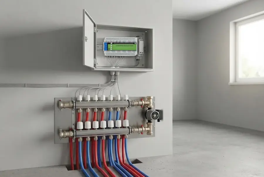
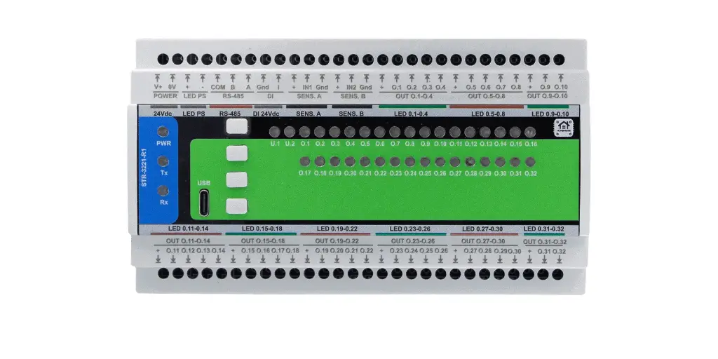
The short version. Each floor loop gets a 24 V thermal actuator, and each actuator gets one output on the STR-3221-R1. With firmware v0.4.0, which the modules ship with, any output can run the Heat profile: the module turns a 0–100 % value per zone into slow on/off cycles, spreads the openings so the supply is not hit all at once, exercises valves that have been shut for weeks, falls back to a frost cycle if the bus goes quiet, and raises a heat-demand flag for the pump. Home Assistant or the controller decides how much each room gets. The module makes sure the valves do it sensibly.
1. Why a Manifold Is Awkward to Automate
A thermal actuator is not a solenoid. It is a small heated wax element that pushes the valve pin over three to five minutes, and lets it back just as slowly. Underfloor heating itself is slower still: a screed floor takes hours to respond. Neither is a problem in itself, but they rule out a few things people try first.
Ordinary relays switch the actuator, but nothing decides how long it should stay open. Fast on/off from an automation either does nothing useful (the actuator never finishes moving) or wears the relay for no gain. Ten to thirty relays also take a lot of panel space.
Battery or Wi-Fi room thermostats that drive the manifold work while their batteries, the Wi-Fi and the vendor's app all do. The manifold is the one part of the heating you do not want to depend on any of those in January.
A dedicated manifold controller handles the actuators properly, but usually as a closed box: its own app, its own room units, a fixed number of zones, and an integration with Home Assistant that someone else maintains.
What the job actually needs is boring: one switched output per loop, slow cycling with a sensible minimum on-time, a limit on how many actuators heat up at once, a valve exercise in summer, a safe behaviour when the controller disappears, and a single signal that says the pump should run.
2. How It Fits Together
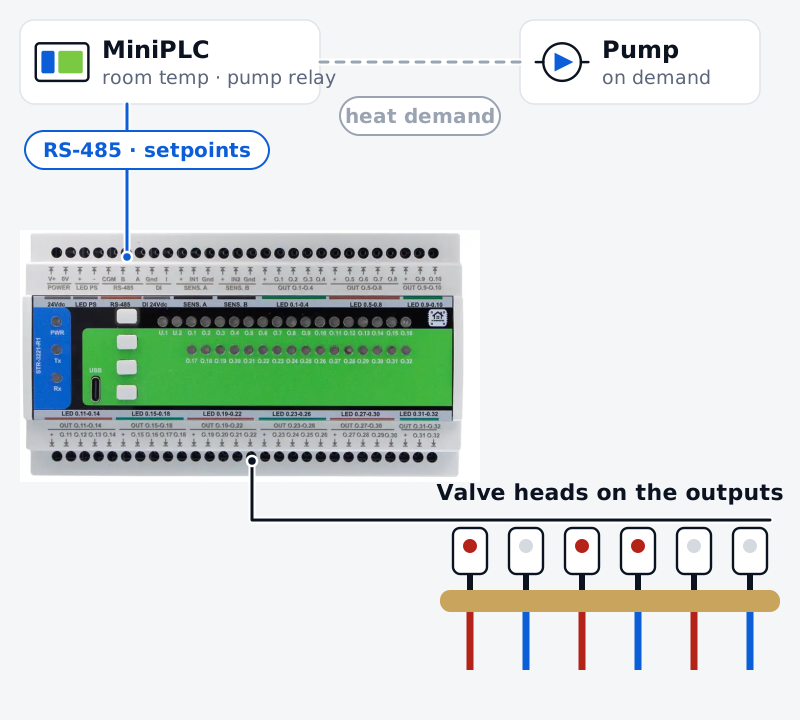
There are three layers, and each one has a clear job.
Home Assistant or the controller decides how much heat each room should get, as a number from 0 to 100 % per zone. That can be a fixed value per room to balance the floor, a schedule, or a value worked out from a room temperature sensor. How you arrive at the number is up to you; the module does not need to know.
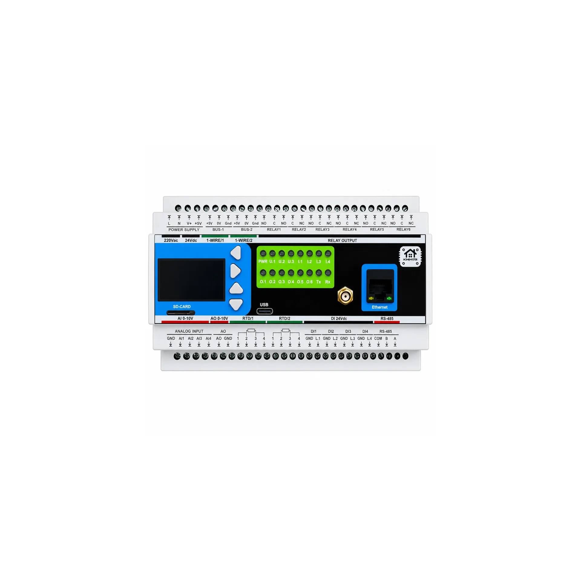
The MiniPLC sits on the RS-485 bus as the Modbus master, writes those values to the module and reads back what the module is doing. It also has the relays, so it is where the circulation pump or the boiler enable is switched from the module's heat-demand flag.
The STR-3221-R1 owns the actuators: it turns each zone's percentage into on/off time, decides which zones may open right now, and keeps running whatever it was last told when everything above it goes quiet.
3. Slow PWM: Turning a Percentage Into Valve Time
An actuator is either powered or not, so "40 %" has to become time. The module does this with a slow PWM cycle per zone: the period is set between 5 and 60 minutes, and a zone at 40 % on a 20-minute period is powered for 8 minutes and off for 12.
Two details make this work with real actuators rather than against them:
- Minimum pulse. A zone asked for 3 % would switch on for a few seconds, which never moves the valve. Below the minimum pulse (10 % by default, adjustable) the zone stays closed; above 100 % minus that value it stays open. A small hysteresis stops it flickering around the threshold.
- Phase spread. Without it, every zone starts its cycle at the same moment and all the actuators heat up together. With phase spread the zones are offset across the period, so the load on the 24 V supply, and on the pump, is smoother.
Choose the period to suit the actuators: comfortably longer than their opening time, and short enough that a room does not swing. Twenty to thirty minutes is a common starting point for screed floors.
4. What the Module Does by Itself
These run on the STR-3221-R1, configured once in WebConfig over USB-C and stored in the module's flash:
- Cap on open zones. You can limit how many zones may be powered at the same moment. A zone that has to wait is not skipped: the time it missed is added to its next cycle. This is what lets a modest supply run a large manifold.
- Valve exercise. A zone that has been closed for a set time (14 days by default) is opened for a few minutes, summer included, so the valve pins do not seize. There is also a button in Home Assistant to exercise all zones now.
- Frost fallback. If the module hears nothing on the bus for a set number of hours, heat zones switch to a fixed cycle of 15 minutes open and 45 minutes closed until the controller comes back. The floor is not left shut with nobody in charge.
- Summer mode. One switch closes all heat zones and clears the heat demand, while valve exercise keeps running.
- Heating enable input. The module's 24 V digital input can be set as enable (zones may open only while it is closed) or inhibit (closing it shuts all zones), for a heat-source ready contact or a manual off switch.
- Heat demand for the pump. When at least one zone is open, the module raises a heat-demand flag, with an adjustable delay after the first zone opens and an overrun after the last one closes, so the pump does not push against shut valves.
- NC or NO per channel, and per-zone counters for hours open and number of cycles, which help spot a zone that is always at 100 % or one that never opens.
The module does not measure temperature and does not run a control loop. It is the part that switches the valves properly; deciding how warm a room should be stays above it.
5. What Keeps Working When Something Fails
| What fails | What the zones do | Pump |
|---|---|---|
| Home Assistant down | Keep cycling at the last value each zone was given | Follows heat demand, if the pump rule is on the MiniPLC |
| Controller or bus down | Keep the last values, then after the set number of hours switch to the 15 / 45 minute frost cycle | Needs its own fallback: the demand flag is read over the bus |
| 24 V supply off | Normally closed actuators close | Not switched by the module |
The practical rule follows from the table: put the pump-from-demand rule on the MiniPLC, in its ESPHome configuration, rather than in a Home Assistant automation. It is a few lines, and it means a server restart does not stop the circulation. The same thinking applies across the house; what still works when Home Assistant is down goes through it module by module.
6. Which Actuators, and How to Size the Supply
The outputs are low-side MOSFET switches for 12–24 V DC loads, rated 1.5 A per channel and 18 A for the whole module. In practice that means:
- 24 V DC thermal actuators. Most common heads are sold as "24 V AC/DC"; check that DC is listed. 230 V actuators cannot be connected, and an AC-only head needs an AC supply the module does not switch.
- Normally closed is the usual choice, so a loop closes when the power is off. NO heads work too; set the channel to NO and the module inverts it.
- Current is not the limit. A typical 24 V head draws roughly 0.1 A once warm and a few hundred milliamps for the first minute or two. That is well inside 1.5 A, so a room with two loops can run two heads in parallel on one output. Check the actuator's datasheet for its starting current.
- Size the supply for the start-up current, not the holding current, multiplied by the number of zones that may open together. This is where the cap on open zones pays off: with 24 zones and a cap of 8, the supply only has to cover 8 heads starting at once.
The outputs switch the negative side. The positive goes to all the actuators from the module's output supply, and each actuator's other wire returns to its own output terminal. None of the field interfaces is galvanically isolated, so keep the actuator wiring SELV, in the same installation and on one 0 V reference.
One module covers 32 zones. A house with two manifolds can run both from one module if the cables reach the panel, or from two modules on the same bus.
7. Setting It Up
In WebConfig (Chrome or Edge, USB-C, no software to install): set each valve channel to the Heat profile and NC or NO, then the heat settings: PWM period, minimum pulse, phase spread, cap on open zones, exercise interval and duration, frost hours, the role of the digital input, and the pump delay and overrun. Channels you do not use for heating stay available for LED strips; one module can drive stair steps, cove lights and valve heads at the same time.
On the controller, the module's ESPHome package brings in the heat demand, open zones, frost and exercise states, summer mode and the exercise button. For each heat zone, swap the default light entity for a 0–100 % number entity, as described in the package file, and you get one slider per room in Home Assistant.
In Home Assistant, set the zone values however suits the house. A fixed value per room is a perfectly good start for balancing a floor; schedules and room sensors can come later without touching the wiring.
The bus itself is one twisted pair plus COM, terminated at both ends; RS-485 and Modbus in ESPHome covers the wiring and the usual faults.
8. What This Is Not
Not a thermostat. No temperature measurement and no control loop on the module.
Not for 230 V actuators. 12–24 V DC loads only.
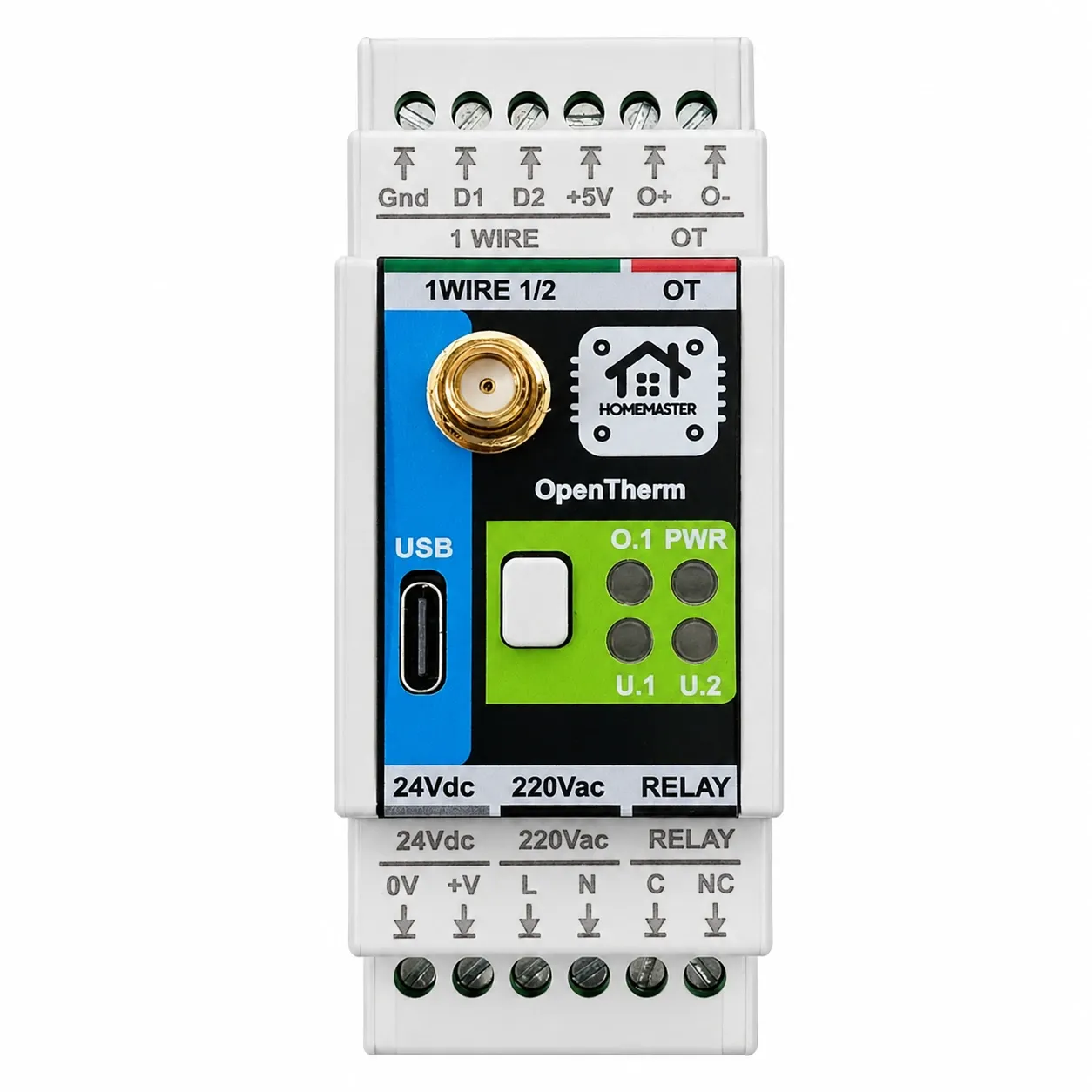
Not a boiler controller. It tells the controller that heat is wanted. Talking to the boiler is a separate job; for OpenTherm boilers see OpenTherm in ESPHome.
Not a pump controller without the controller. The pump is switched by a MiniPLC relay from the demand flag. On a MicroPLC the relay is C / NC only, so check that this matches how your pump should behave when the relay is off.
Not galvanically isolated. Surge protection on every channel and input, which is not the same thing.
9. The Takeaway
The difficult part of an underfloor heating manifold is not deciding how warm a room should be. It is everything around that: actuators that need minutes rather than milliseconds, a supply that should not see every head start at once, valves that seize if they sit closed all summer, and a pump that should follow the valves even when the server is restarting.
Put that on the module that switches the actuators, keep the pump rule on the controller, and the room-level logic in Home Assistant can be as simple or as clever as you like, and can change at any time without touching a wire.
If you are planning the whole house rather than one manifold, wiring a new house for Home Assistant covers what to pull before the walls close, and the System Builder turns a room list into a module count.